COPYRIGHT © 2002 VICTOR COMPANY OF JAPAN, LTD
This service manual is printed on 100% recycled paper.
SERVICE MANUAL
Regarding service information other than these sections, refer to the service manual No. 82911 (HR-S5901U).
Also, be sure to note important safety precautions provided in the service manual.
Specifications shown are for SP mode unless specified otherwise.
E. & O.E. Design and specifications subject to change without
notice.
GENERAL
Power requirement
: AC 110 V 220 Vd, 50 Hz/60 Hz
Power consumption
Power on
: 18 W
Power off
: 3.0 W
Temperature
Operating
: 5
°C to 40°C
Storage
: 20
°C to 60°C
Operating position
: Horizontal only
Dimensions (W x H x D) : 435 mm x 94 mm x 247 mm
Weight
: 2.7 kg
Format
: S-VHS/VHS NTSC standard
Maximum recording time
SP
: 210 min. with ST-210 video cassette
EP
: 630 min. with ST-210 video cassette
VIDEO/AUDIO
Signal system
: NTSC-type color signal and EIA
monochrome signal, 525 lines/
60 fields
Recording/Playback
system
: DA-4 (Double Azimuth) head helical
scan system
Signal-to-noise ratio
: 45 dB
Horizontal resolution
VHS
: 230 lines
S-VHS
: 400 lines
Frequency range
Normal audio
: 70 Hz to 10,000 Hz
Hi-Fi audio
: 20 Hz to 20,000 Hz
Input/Output
: RCA connectors (IN x 1, OUT x 1)
S-video connector (OUT x 1)
TUNER
Tuning system
: Frequency-synthesized tuner
Channel coverage
VHF
: Channels 213
UHF
: Channels 1469
CATV
: 113 Channels
RF output
: Channel 3 or 4 (switchable; preset to
Channel 3 when shipped) 75 ohms,
unbalanced
TIMER
Clock reference
: Quartz
Program capacity
: 1-year programmable timer/
8programs
Memory backup time
: Approx. 6 months
Estimated figure based on supplied
fresh battery; actual performance may
differ.
ACCESSORIES
Provided accessories
: RF cable,
Lithium battery CR2025,
Infrared remote control unit,
"AA" battery x 2,
Conversion plug
S-video cable (4-pin)
No.82929
August 2002
HR-S8009UM
HR-S8009UM V15S0
VIDEO CASSETTE RECORDER
SPECIFICATIONS
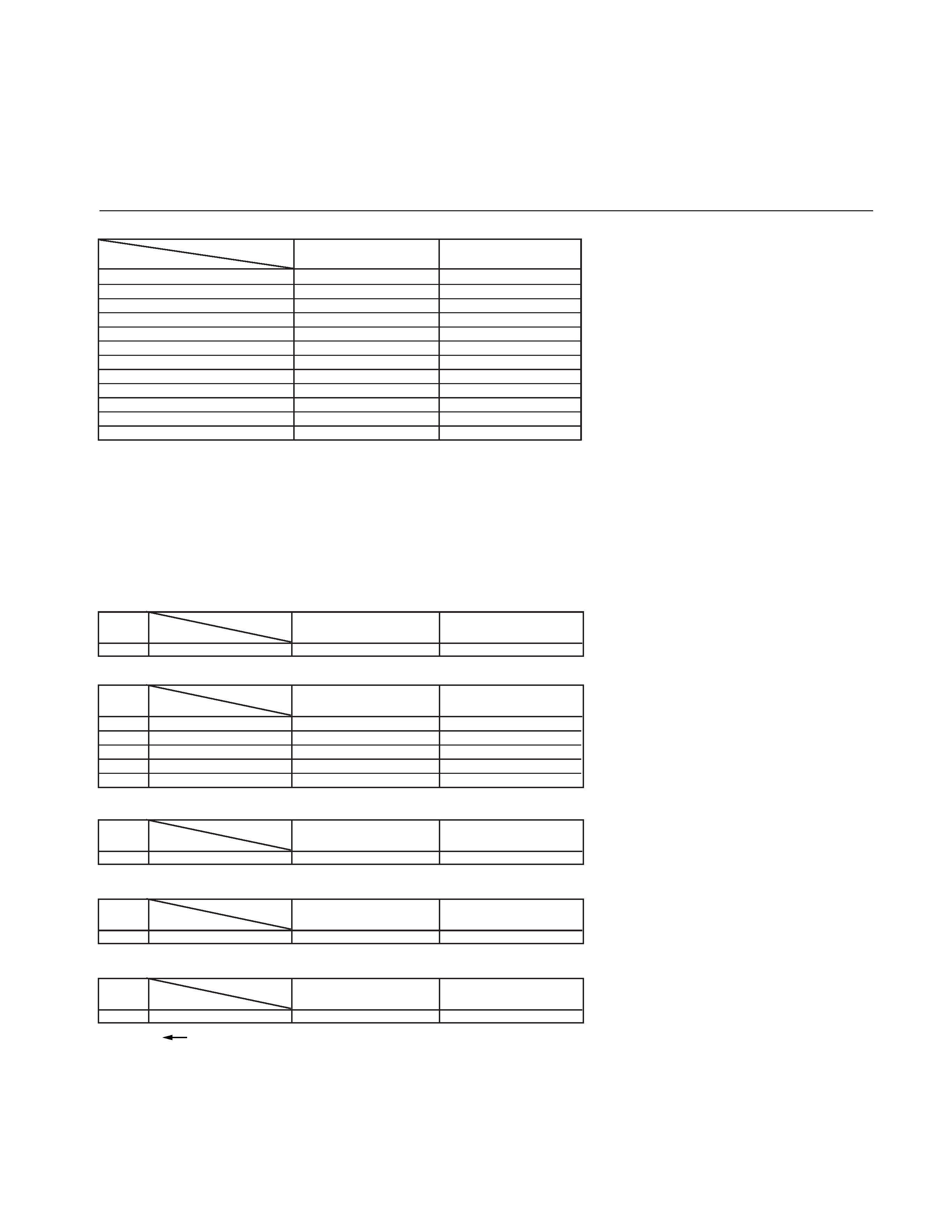
TABLE OF CONTENTS
The following table indicates main different points between models HR-S5901U and HR-S8009UM.
MODEL
HR-S5901U
ITEM
CABINET COLOR
BLACK
PURE SILVER
ADVANCED JOG
USED
NOT USED
ILLUMI FUNCTION
USED
NOT USED
FLYING ERASE HEAD
USED
NOT USED
INSERT
USED/BUTTON
NOT USED
AUDIO DUBBING
USED/BUTTON
NOT USED
FRONT S JACK
USED
NOT USED
REAR S, A/V JACK
USED
NOT USED
VCR PLUS+
USED
NOT USED
REC LINK
USED
NOT USED
CABLE BOX/DBS.BOX CONTROL
USED
NOT USED
BACK UP
NOT USED
USED
HR-S8009UM
DIFFERENT TABLE .............................................................................................................................................................................................. 1 only
3 .ADJUSTMENT (3-1 only) .................................................................................................................................................................... 3-1 only
5. PARTS LIST (5-1 to 5-9)
5.1
PACKING AND ACCESSORY ASSEMBLY <M1> ................................................................................................................................. 5-1
5.2
FINAL ASSEMBLY <M2> ....................................................................................................................................................................... 5-2
5.3
ELECTRICAL PART LIST <M2> ............................................................................................................................................................ 5-4
MAIN BOARD ASSEMBLY<03>
The following table indicates different parts number between models HR-S5901U and HR-S8009UM.
PACKING AND ACCESSORY ASSEMBLY<M1>
PACKING AND ACCESSORY ASSEMBLY<M1> is indicated on the parts list.
FINAL ASSEMBLY<M2>
FINAL ASSEMBLY<M2> is indicated on the parts list.
MAIN BOARD ASSEMBLY<03>
REF
NO.
!
MODEL
ITEM
PW1
MAIN BOARD ASSY
LPA10155-02C1
LPA10155-05A1
HR-S5901U
HR-S8009UM
Note: Mark
is same as left.
Mark -- is not used.
1
REAR S JACK BOARD ASSEMBLY <29>
REF
NO.
!
MODEL
ITEM
PW5
REAR S JACK BOARD ASSY
LPA10155-01A5
LPA10155-02A5
R928
MG RESISTOR
NRSA02J-750X
-----
R929
MG RESISTOR
NRSA02J-750X
-----
C915
MG RESISTOR
NRSA02J-0R0X
-----
J4
S JACK
QND0077-001
QND0076-001
HR-S5901U
HR-S8009UM
FRONT S JACK BOARD ASSEMBLY <36>
REF
NO.
!
MODEL
ITEM
PW4
FRONT S JACK BOARD ASSY
LPA10155-01A4
-----
HR-S5901U
HR-S8009UM
ADV.JOG/SW BOARD ASSEMBLY <38>
REF
NO.
!
MODEL
ITEM
PW6
ADV.JOG/SW BOARD ASSY
LPA10155-01A6
----
HR-S5901U
HR-S8009UM
R.PAUSE BOARD ASSEMBLY <99>
REF
NO.
!
MODEL
ITEM
PW2
R.PAUSE BOARD ASSY
LPA10155-02A2
----
HR-S5901U
HR-S8009UM
SECTION 3
ADJUSTMENT
(1) Connect the frequency counter to the measuring point
(D1).
(2) Connect the short wire between the short point (D2) and
GND.
(3) Connect the short wire between the short point (D3) and
GND in order to reset the microprocessor of the SYSCON.
(4) Adjust the adjustment part (F) so that the output frequency
becomes the specified value(G).
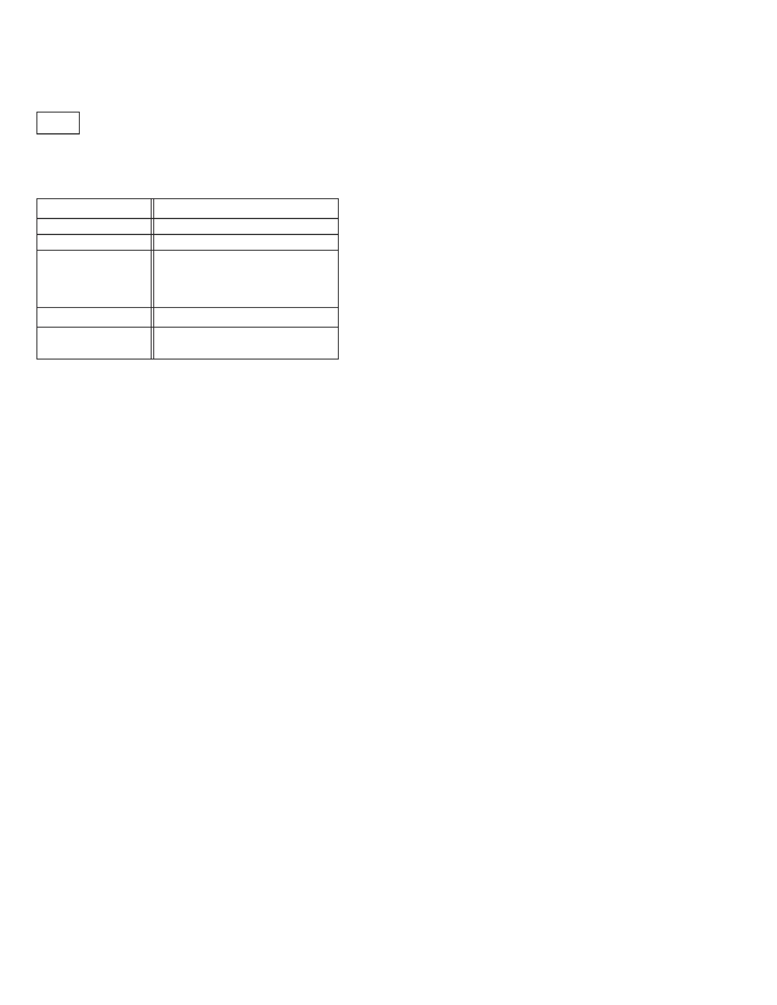
3.3
Electrical adjustment
Signal
(A)
· No signal
Mode
(B)
· EE
Equipment
(C)
· Frequency counter
Measuring point
(D1)
· IC3001 pin 29
Short point
(D2)
· IC3001 pin 32
(D3)
·IC3001 pin 25
Adjustment part
(F)
· C3018(Timer clock)
Specified value
(G)
· 998.757
±0.024 Hz
· (1001.244
±0.024µ sec)
3.3.4.1 TIMER CLOCK
3.3.4 SYSCON circuit
3-1
The difference point(s) compared with the reference model are as follows.
Add

VICTOR COMPANY OF JAPAN, LIMITED
12,3-chome,Moriya-cho,Kanagawa-ku,Yokohama,Kanagawa-prefecture,221-8528,Japan
HOME AV NETWORK BUSINESS UNIT.
Printed in Japan
0208 WPC