COPYRIGHT © 2003 VICTOR COMPANY OF JAPAN, LTD
SERVICE MANUAL
Specifications shown are for SP mode unless otherwise specified.
Design and specifications subject to change without notice.
GENERAL
Power requirement
Rating
: AC 110 V 240 Vd, 50 Hz/60 Hz
Operating
: AC 90 V 260 Vd, 50 Hz/60 Hz
Power consumption
: 20 W
Temperature
Operating
: 5
°C to 40°C
Storage
: 20
°C to 60°C
Operating position
: Horizontal only
Dimensions (W x H x D) : 400 mm x 94 mm x 278 mm
Weight
: 3.4 kg
Format
: S-VHS/VHS standard
Maximum recording time
(SP)
: 240 min. with E-240 video cassette
(PAL/MESECAM)
: 160 min. with T-160 video cassette
(NTSC)
(LP)
: 480 min. with E-240 video cassette
(PAL/MESECAM)
(EP)
: 720 min. with E-240 video cassette
(PAL/MESECAM)
: 480 min. with T-160 video cassette
(NTSC)
VIDEO/AUDIO
Signal system
: PAL-type colour signal and CCIR
monochrome signal, 625 lines/
50 fields
: NTSC colour and EIA monochrome
signals, 525 lines/60 fields
Recording system
: DA-4 (Double Azimuth) head helical
scan system
Signal-to-noise ratio
: 45 dB
Horizontal resolution
S-VHS
: 400 lines
VHS PAL/MESECAM : 250 lines
VHS NTSC
: 220 lines
Frequency range
Normal audio
: 70 Hz to 10,000 Hz
Hi-Fi audio
: 20 Hz to 20,000 Hz
Input/Output
: RCA connectors:
IN x 2, OUT x 1
S-Video connectors:
IN x 2, OUT x 1
TUNER/TIMER
TV channel storage
capacity
: 99 positions (+AUX position)
Tuning system
: Frequency synthesized tuner
Channel coverage
VHF
: (Low) 42 MHz 175 MHz/
(High) 175 MHz 470 MHz
UHF
: 470 MHz 870 MHz
Aerial output
: UHF channels (Adjustable E28 E60)
Memory backup time
: Approx. 6 months
Estimated figure based on supplied
fresh battery; actual performance may
differ.
ACCESSORIES
Provided accessories
: RF cable,
S-Video cable,
Infrared remote control unit,
"R6/UM-3" battery x 2,
Lithium battery CR2025
No.82981
2003/07
HR-S5980AH, HR-S5980AJ
HR-S5980AH, HR-S5980AJ V15S15
VIDEO CASSETTE RECORDER
SPECIFICATIONS (The specifications shown pertain specifically to the model HR-S5980AH.)
CABLE/
SAT/DVD
TV
VCR

TABLE OF CONTENTS
Section
Title
Page
Section
Title
Page
Important Safety Precautions
INSTRUCTIONS
1. DISASSEMBLY
1.1 Disassembly flow chart ..................................................... 1-1
1.2 How to read the disassembly and assembly ..................... 1-1
1.3 Disassembly/assembly method ........................................ 1-1
1.4 Service position ................................................................. 1-4
1.4.1 How to set the "Service position" ................................. 1-4
1.5 Mechanism service mode ................................................. 1-4
1.5.1 How to set the "Mechanism service mode" .................. 1-4
1.6 Jig RCU mode ................................................................... 1-4
1.6.1 Setting the Jig RCU mode ........................................... 1-4
1.6.2 Setting the User RCU mode ........................................ 1-4
1.7 Servicing items related to video navigation ....................... 1-4
1.8 Emergency display function .............................................. 1-5
1.8.1 Displaying the EMG information .................................. 1-5
1.8.2 Clearing the EMG history ............................................. 1-5
1.8.3 EMG content description .............................................. 1-6
1.8.4 EMG detail information <1> ......................................... 1-7
1.8.5 EMG detail information <2> ......................................... 1-8
2. MECHANISM ADJUSTMENT
2.1 Before starting repair and adjustment ............................... 2-1
2.1.1 Precautions .................................................................. 2-1
2.1.2 Checking for proper mechanical operations ................ 2-1
2.1.3 Manually removing the cassette tape .......................... 2-1
2.1.4 Jigs and tools required for adjustment ......................... 2-2
2.1.5 Maintenance and inspection ........................................ 2-3
2.2 Replacement of major parts .............................................. 2-6
2.2.1 Before starting disassembling
(Phase matching between mechanical parts) ............... 2-6
2.2.2 How to set the "Mechanism assembling mode" ........... 2-6
2.2.3 Cassette holder assembly ............................................ 2-6
2.2.4 Pinch roller arm assembly ............................................ 2-8
2.2.5 Guide arm assembly and press lever assembly .......... 2-8
2.2.6 A/C head ...................................................................... 2-8
2.2.7 Loading motor .............................................................. 2-8
2.2.8 Capstan motor ............................................................. 2-9
2.2.9 Pole base assembly (supply or take-up side) .............. 2-9
2.2.10 Rotary encoder ........................................................ 2-10
2.2.11 Clutch unit ................................................................ 2-10
2.2.12 Change lever assembly, direct gear,
clutch gear and coupling gear .................................. 2-10
2.2.13 Link lever .................................................................. 2-11
2.2.14 Cassette gear, control cam and worm gear ............. 2-11
2.2.15 Control plate ............................................................. 2-11
2.2.16 Loading arm gear (supply or take-up side)
and loading arm gear shaft ...................................... 2-12
2.2.17 Take-up lever, take-up head and control plate guide... 2-13
2.2.18 Capstan brake assembly ......................................... 2-13
2.2.19 Sub brake assembly (take-up side) ......................... 2-13
2.2.20 Main brake assembly (take-up side),
reel disk (take-up side) and
main brake assembly (supply side) ........................... 2-13
2.2.21 Tension brake assembly, reel disk (supply side)
and tension arm assembly ....................................... 2-14
2.2.22 Idler lever, idler arm assembly ................................. 2-14
2.2.23 Stator assembly ....................................................... 2-14
2.2.24 Rotor assembly ........................................................ 2-14
2.3 Compatibility adjustment ................................................. 2-15
2.3.1 FM waveform linearity ................................................ 2-15
2.3.2 Height and tilt of the A/C head ................................... 2-16
2.3.3 A/C head phase (X-value) .......................................... 2-16
2.3.4 Standard tracking preset ............................................ 2-17
2.3.5 Tension pole position .................................................. 2-17
3. ELECTRICAL ADJUSTMENT
3.1 Precaution ......................................................................... 3-1
3.1.1 Required test equipments ............................................ 3-1
3.1.2 Required adjustment tools ........................................... 3-1
3.1.3 Color (colour) bar signal,Color (colour) bar pattern ..... 3-1
3.1.4 Switch settings and standard precautions ................... 3-1
3.1.5 EVR Adjustment ........................................................... 3-1
3.2 Servo circuit ...................................................................... 3-2
3.2.1 Switching point ............................................................. 3-2
3.2.2 Slow tracking preset ..................................................... 3-2
3.3 Video circuit ....................................................................... 3-2
3.3.1 D/A level ....................................................................... 3-2
3.3.2 EE Y/PB Y (S-VHS/VHS) level ..................................... 3-2
3.3.3 REC color (colour) level ............................................... 3-3
3.3.4 Video EQ (Frequency response) .................................. 3-3
3.3.5 Auto picture initial setting ............................................. 3-4
3.4 Audio circuit ....................................................................... 3-4
3.4.1 Audio REC FM ............................................................. 3-4
3.5 Syscon circuit .................................................................... 3-4
3.5.1 Timer clock ................................................................... 3-4
4. CHARTS AND DIAGRAMS
NOTES OF SCHEMATIC DIAGRAM ...................................... 4-1
CIRCUIT BOARD NOTES ...................................................... 4-2
4.1 BOARD INTERCONNECTIONS ....................................... 4-3
4.2 MAIN (VIDEO/AUDIO) SCHEMATIC DIAGRAM .............. 4-5
4.3 MAIN (ON SCREEN) SCHEMATIC DIAGRAM ................. 4-7
4.4 MAIN (SYSCON) SCHEMATIC DIAGRAM ....................... 4-9
4.5 MAIN (SW.REG) SCHEMATIC DIAGRAM ...................... 4-11
4.6 MAIN (TUNER) SCHEMATIC DIAGRAM ........................ 4-13
4.7 MAIN (SW/DISPLAY), S-JACK AND ADV.JOG
SCHEMATIC DIAGRAMS ............................................... 4-15
4.8 MAIN (MAIN TERMINAL) SCHEMATIC DIAGRAM ........ 4-17
4.9 2D DIGITAL SCHEMATIC DIAGRAM ............................. 4-19
4.10 TERMINAL (S-SUB) SCHEMATIC DIAGRAM .............. 4-21
4.11 TERMINAL (I/O) SCHEMATIC DIAGRAM .................... 4-23
4.12 DEMODULATOR SCHEMATIC DIAGRAM ................... 4-25
4.13 2D DIGITAL AND DEMODULATOR CIRCUIT BOARDS ... 4-27
4.14 TERMINAL CIRCUIT BOARD ....................................... 4-28
4.15 MAIN CIRCUIT BOARD ................................................ 4-29
4.16 REMOTE CONTROLLER SCHEMATIC DIAGRAM ..... 4-32
4.17 FDP GRID ASSIGNMENT AND ANODE CONNECTION .. 4-33
4.18 WAVEFORMS ............................................................... 4-34
4.19 VOLTAGE CHARTS ...................................................... 4-36
4.20 CPU PIN FUNCTION .................................................... 4-37
4.21 SYSTEM CONTROL BLOCK DIAGRAM ...................... 4-39
4.22 VIDEO BLOCK DIAGRAM ............................................ 4-41
4.23 AUDIO BLOCK DIAGRAM ............................................ 4-45
5. PARTS LIST
5.1 EXPLODED VIEW ............................................................. 5-1
5.1.1 PACKING AND ACCESSORY ASSEMBLY <M1> ...... 5-1
5.1.2 FINAL ASSEMBLY <M2> ............................................ 5-2
5.1.3 MECHANISM ASSEMBLY <M4> ................................ 5-3
5.2 PARTS LIST ....................................................................... 5-4
PACKING AND ACCESSORY ASSEMBLY<M1> ................. 5-4
FINAL ASSEMBLY<M2> ....................................................... 5-4
MECHANISM ASSEMBLY<M4> ........................................... 5-4
MAIN BOARD ASSEMBLY <03> ......................................... 5-6
2D DIGITAL BOARD ASSEMBLY <05> ............................. 5-13
TERMINAL BOARD ASSEMBLY <06> .............................. 5-14
A/C HEAD BOARD ASSEMBLY <12> ............................... 5-15
DEMOD BOARD ASSEMBLY <14> ................................... 5-15
S.JACK BOARD ASSEMBLY <36> .................................... 5-15
ADV.JOG BOARD ASSEMBLY <38> ................................. 5-15
LOADING MOTOR BOARD ASSEMBLY <55> .................. 5-15
The following table indicates main different points between models HR-S5980AH and HR-S5980AJ.
Notes: Mark
is same as left.
MODEL
HR-S5980AH
ITEM
POWER PLUG
HK3PIN(CLS II)
UL, CSA
HR-S5980AJ
Important Safety Precautions
Prior to shipment from the factory, JVC products are strictly inspected to conform with the recognized product safety and electrical codes
of the countries in which they are to be sold. However, in order to maintain such compliance, it is equally important to implement the
following precautions when a set is being serviced.
Fig.1
1. Locations requiring special caution are denoted by labels and
inscriptions on the cabinet, chassis and certain parts of the
product. When performing service, be sure to read and com-
ply with these and other cautionary notices appearing in the
operation and service manuals.
2. Parts identified by the
symbol and shaded (
) parts are
critical for safety.
Replace only with specified part numbers.
Note: Parts in this category also include those specified to com-
ply with X-ray emission standards for products using
cathode ray tubes and those specified for compliance
with various regulations regarding spurious radiation
emission.
3. Fuse replacement caution notice.
Caution for continued protection against fire hazard.
Replace only with same type and rated fuse(s) as specified.
4. Use specified internal wiring. Note especially:
1) Wires covered with PVC tubing
2) Double insulated wires
3) High voltage leads
5. Use specified insulating materials for hazardous live parts.
Note especially:
1) Insulation Tape
3) Spacers
5) Barrier
2) PVC tubing
4) Insulation sheets for transistors
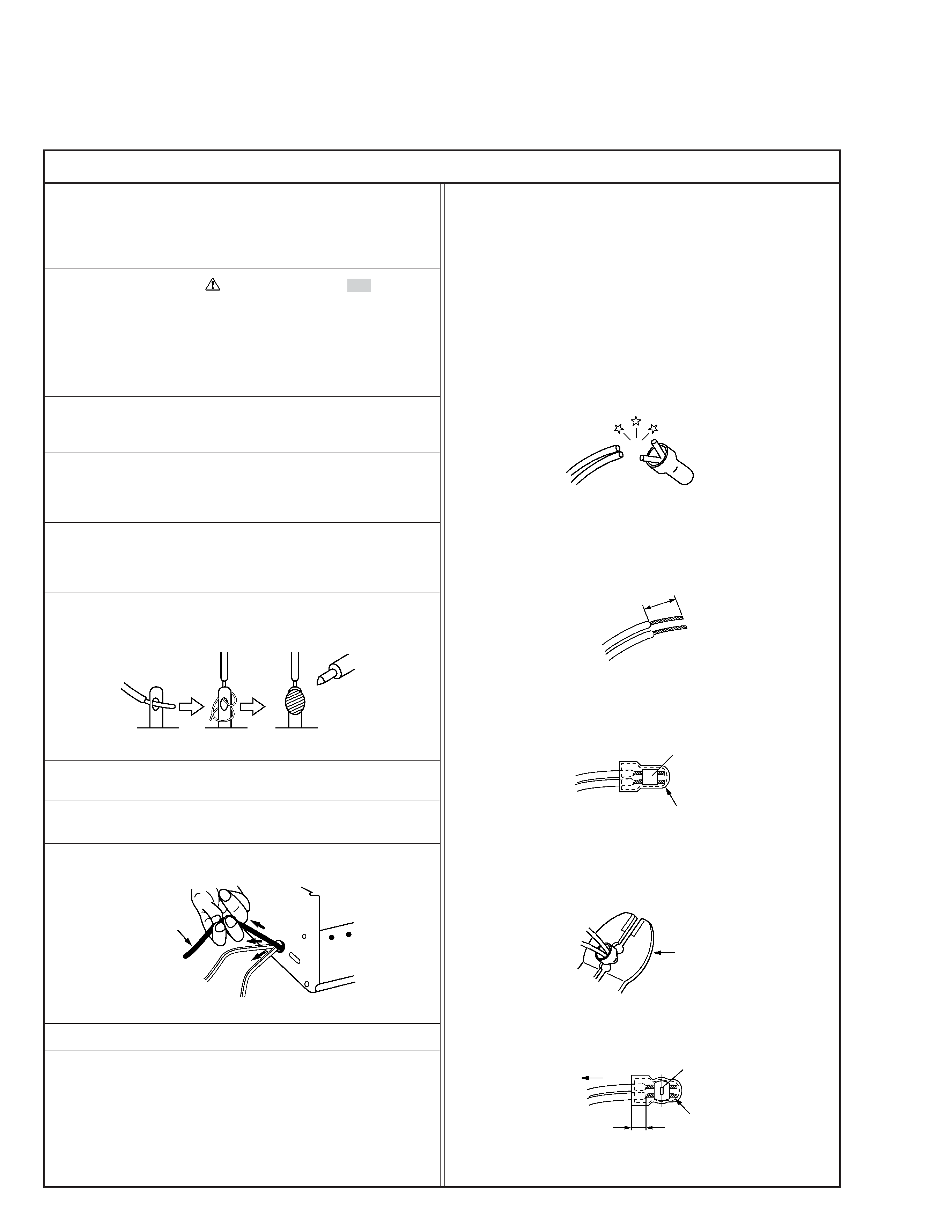
6. When replacing AC primary side components (transformers,
power cords, noise blocking capacitors, etc.) wrap ends of
wires securely about the terminals before soldering.
Power cord
Fig.2
10. Also check areas surrounding repaired locations.
11. Products using cathode ray tubes (CRTs)
In regard to such products, the cathode ray tubes themselves,
the high voltage circuits, and related circuits are specified for
compliance with recognized codes pertaining to X-ray emission.
Consequently, when servicing these products, replace the cath-
ode ray tubes and other parts with only the specified parts.
Under no circumstances attempt to modify these circuits.
Unauthorized modification can increase the high voltage value
and cause X-ray emission from the cathode ray tube.
12. Crimp type wire connector
In such cases as when replacing the power transformer in sets
where the connections between the power cord and power
transformer primary lead wires are performed using crimp type
connectors, if replacing the connectors is unavoidable, in or-
der to prevent safety hazards, perform carefully and precisely
according to the following steps.
1) Connector part number : E03830-001
2) Required tool : Connector crimping tool of the proper type
which will not damage insulated parts.
3) Replacement procedure
(1) Remove the old connector by cutting the wires at a point
close to the connector.
Important : Do not reuse a connector (discard it).
Fig.7
cut close to connector
Fig.3
(2) Strip about 15 mm of the insulation from the ends of
the wires. If the wires are stranded, twist the strands to
avoid frayed conductors.
15 mm
Fig.4
(3) Align the lengths of the wires to be connected. Insert
the wires fully into the connector.
Connector
Metal sleeve
Fig.5
(4) As shown in Fig.6, use the crimping tool to crimp the
metal sleeve at the center position. Be sure to crimp fully
to the complete closure of the tool.
1
Precautions during Servicing
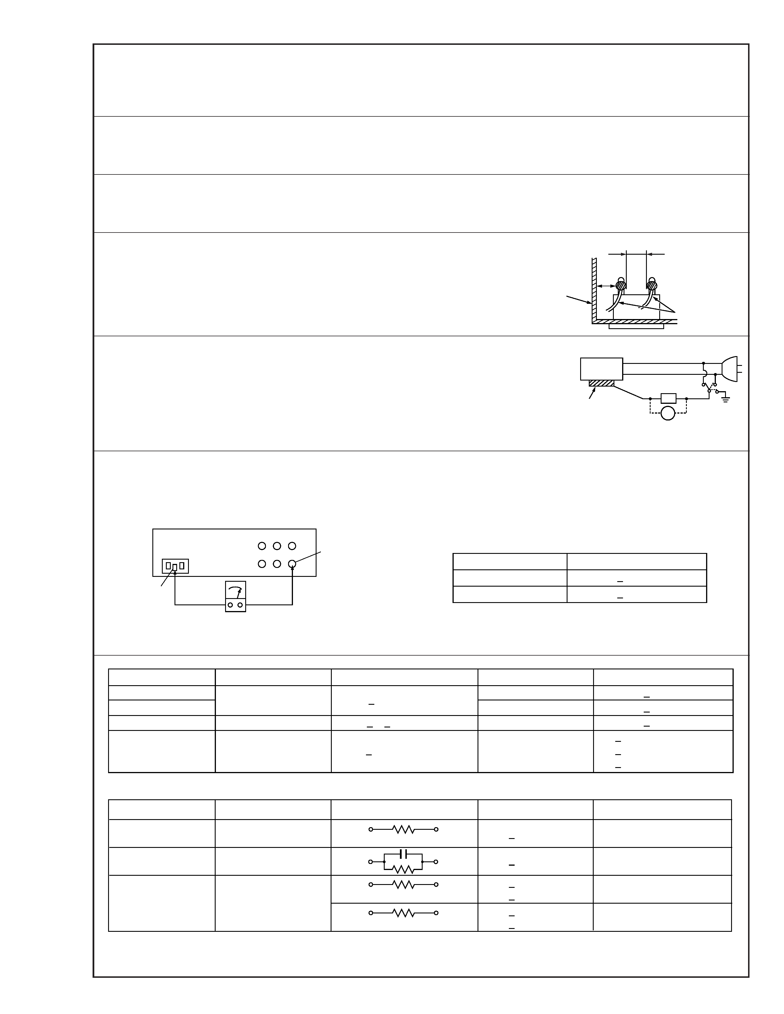
7. Observe that wires do not contact heat producing parts
(heatsinks, oxide metal film resistors, fusible resistors, etc.)
8. Check that replaced wires do not contact sharp edged or
pointed parts.
9. When a power cord has been replaced, check that 10-15 kg of
force in any direction will not loosen it.
1.25
2.0
5.5
Crimping tool
Fig.6
(5) Check the four points noted in Fig.7.
Not easily pulled free
Crimped at approx. center
of metal sleeve
Conductors extended
Wire insulation recessed
more than 4 mm
S40888-01
Safety Check after Servicing
Examine the area surrounding the repaired location for damage or deterioration. Observe that screws, parts and wires have been
returned to original positions, Afterwards, perform the following tests and confirm the specified values in order to verify compli-
ance with safety standards.
1. Insulation resistance test
Confirm the specified insulation resistance or greater between power cord plug prongs and
externally exposed parts of the set (RF terminals, antenna terminals, video and audio input
and output terminals, microphone jacks, earphone jacks, etc.). See table 1 below.
2. Dielectric strength test
Confirm specified dielectric strength or greater between power cord plug prongs and exposed
accessible parts of the set (RF terminals, antenna terminals, video and audio input and output
terminals, microphone jacks, earphone jacks, etc.). See table 1 below.
3. Clearance distance
When replacing primary circuit components, confirm specified clearance distance (d), (d') be-
tween soldered terminals, and between terminals and surrounding metallic parts. See table 1
below.
4. Leakage current test
Confirm specified or lower leakage current between earth ground/power cord plug prongs
and externally exposed accessible parts (RF terminals, antenna terminals, video and audio
input and output terminals, microphone jacks, earphone jacks, etc.).
Measuring Method : (Power ON)
Insert load Z between earth ground/power cord plug prongs and externally exposed accessi-
ble parts. Use an AC voltmeter to measure across both terminals of load Z. See figure 9 and
following table 2.
5. Grounding (Class 1 model only)
Confirm specified or lower grounding impedance between earth pin in AC inlet and externally exposed accessible parts (Video in,
Video out, Audio in, Audio out or Fixing screw etc.).
Measuring Method:
Connect milli ohm meter between earth pin in AC inlet and exposed accessible parts. See figure 10 and grounding specifications.
d'
d
Chassis
Power cord,
primary wire
Region
USA & Canada
Europe & Australia
Grounding Impedance (Z)
Z
0.1 ohm
Z
0.5 ohm
AC inlet
Earth pin
Exposed accessible part
Milli ohm meter
Grounding Specifications
Fig. 10
ab
c
V
Externally
exposed
accessible part
Z
Fig. 9
Fig. 8
Clearance Distance (d), (d')
d, d'
3 mm
d, d'
4 mm
d, d'
3.2 mm
1 M
R 12 M/500 V DC
Dielectric Strength
AC 1 kV 1 minute
AC 1.5 kV 1 miute
AC 1 kV 1 minute
AC Line Voltage
100 V
100 to 240 V
110 to 130 V
110 to 130 V
200 to 240 V
Japan
USA & Canada
Europe & Australia
R
10 M
/500 V DC
Region
Insulation Resistance (R)
R
1 M
/500 V DC
AC 3 kV 1 minute
(Class
2)
AC 1.5 kV 1 minute
(Class
1)
d
4 mm
d'
8 mm (Power cord)
d'
6 mm (Primary wire)
Table 1 Specifications for each region
a, b, c
Leakage Current (i)
AC Line Voltage
100 V
110 to 130 V
110 to 130 V
220 to 240 V
Japan
USA & Canada
i
1 mA rms
Exposed accessible parts
Exposed accessible parts
Antenna earth terminals
Other terminals
i
0.5 mA rms
i
0.7 mA peak
i
2 mA dc
i
0.7 mA peak
i
2 mA dc
Europe & Australia
Region
Load Z
1 k
2 k
1.5 k
0.15
µF
50 k
Table 2 Leakage current specifications for each region
Note: These tables are unofficial and for reference only. Be sure to confirm the precise values for your particular country and locality.
2
S40888-01
1-1
-----------------
-----------------
-----------------
-----------------
[1]
Top cover,
D1 4(S1a), (S1b)
Bracket
2(S1c)
[2]
Front panel assembly
D2 CN7001(WR2a),
<Note 2a>
CN916(WR2b),
<Note 2b>
4(L2a), 3(L2b)
<Note 2c>
ADV. Jog board assembly
2(S2a)
S Jack board assembly
2(S2b)
[3]
Drum assembly
D3 CON1(WR3a),
<Note 2c>
CN1(WR3b),
(S3a), (S3b), (S3c)
(Inertia plate)
4(L3a)
(Roller arm assy)
(P3), (L3b)
(Cleaner assy)
(L3c)
[4]
Mechanism assembly D4 CN2001(WR4a),
<Note 2c>
(S4a),(S4b),
<Note 4a>
(S4c), (S4d)
[5]
Main board assembly
D5 7(L5a),
(S5a), 3(S5b)
SECTION 1
DISASSEMBLY
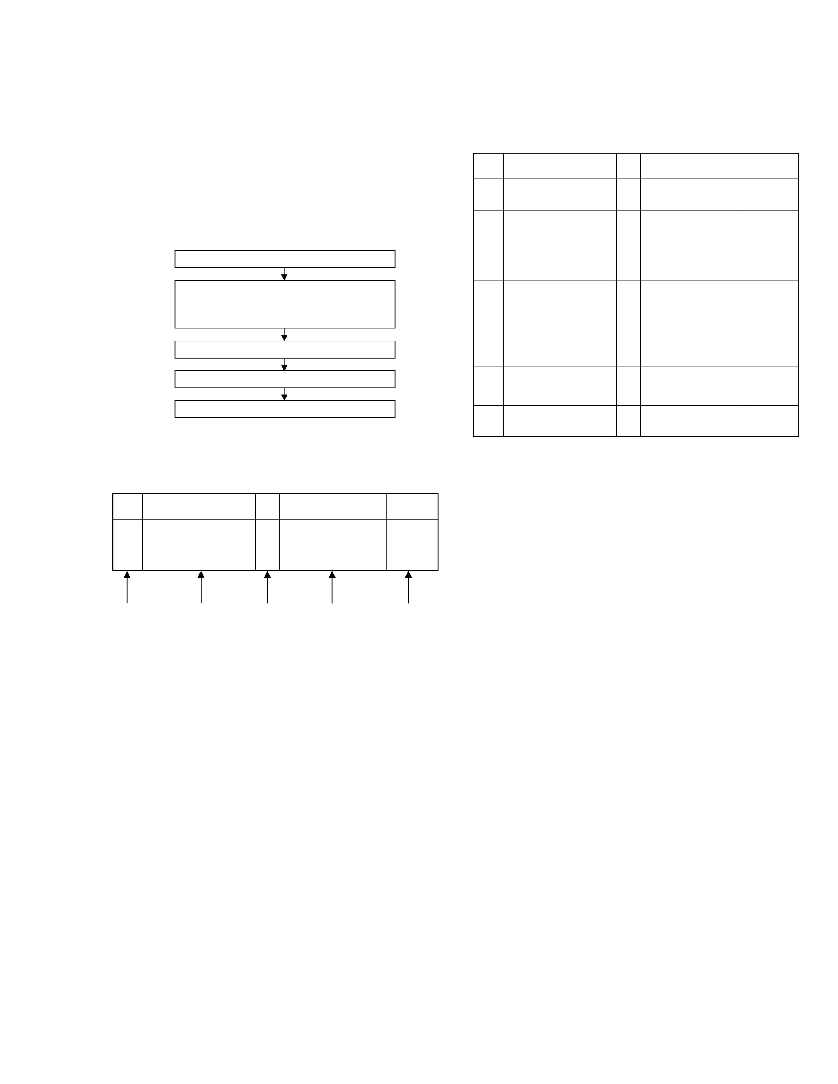
1.3 Disassembly/assembly method
1.1 Disassembly flow chart
This flowchart lists the disassembling steps for the cabinet
parts and P.C. boards in order to gain access to item(s) to
be serviced. When reassembling, perform the step(s) in re-
verse order. Bend, route and dress the flat cables as they
were originally laid.
1.2 How to read the disassembly and assembly
Note:
·
The bracketed ( ) WR of the connector symbol are as-
signed nos. in priority order and do not correspond to
those on the spare parts list.
(5) Adjustment information for installation
Top cover, Bracket
Front panel assembly,
ADV. Jog board assembly,
S Jack board assembly
Drum assembly
Mechanism assembly
Main board assembly
[1]
[2]
[3]
[4]
[5]
Step/
LocNo.
Part Name
Fig.
No.
Point
Note
-----------------
(1)
(2)
(3)
(4)
(5)
Step/
LocNo.
Part Name
Fig.
No.
Point
Note
[1]
Top cover,
D1 4(S1a),(S1b),3(L1a),
<Note 1a>
2(SD1a),(P1a),(W1a),
CN1(WR1a),
Bracket
2(S1c)
<Example>
(1) Order of steps in Procedure
When reassembling, perform the step(s) in the reverse order.
These numbers are also used as the identification (location) No.
of parts Figures.
(2) Part name to be removed or installed.
(3) Fig. No. showing procedure or part location.
(4) Identification of part to be removed, unhooked, unlocked,
released, unplugged, unclamped or unsoldered.
P= Spring, W= Washer, S= Screw, L= Locking tab, SD= Solder,
CN**(WR**)= Remove the wire (WR**) from the connector
(CN**).
<Note 2a>
· When reattaching the Front panel assembly, make sure that
the door opener "a" of the Cassette holder assembly is low-
ered in position prior to the reinstallation.
<Note 2b>
· When reattaching the Front panel assembly, pay careful at-
tention to the switch lever not to make it touch the switch
knob "b" of the Main board assembly from the side.
<Note 2c>
· Be careful not to damage the connector and wire etc. during
connection and disconnection.
When connecting the wire to the connector, be careful with
the wire direction.
<Note 4a>
· When it is required to remove the screws (S4a to S4b) re-
taining the Mechanism assembly, please refer to the "Pro-
cedures for Lowering the Cassette holder assembly"(See
on page 1-2).
· When reattaching the Mechanism assembly to the Main
board assembly, take care not to damage the sensors and
switch on the Main board assembly.
· When removing the Mechanism assembly only, unhook the
two spacers connecting it with the Main board assembly
with pliers from the back side of the Main board assembly
first, and then remove the Mechanism assembly.
· The wire (WR4a) has excess length that may be loose, as it
is quite long. After inserting the wire and connectors, the
loose portion of the wire should be taken up and accommo-
dated between the A/C head base and the main deck.
-----------------