SERVICE MANUAL
No. 82828
September 2000
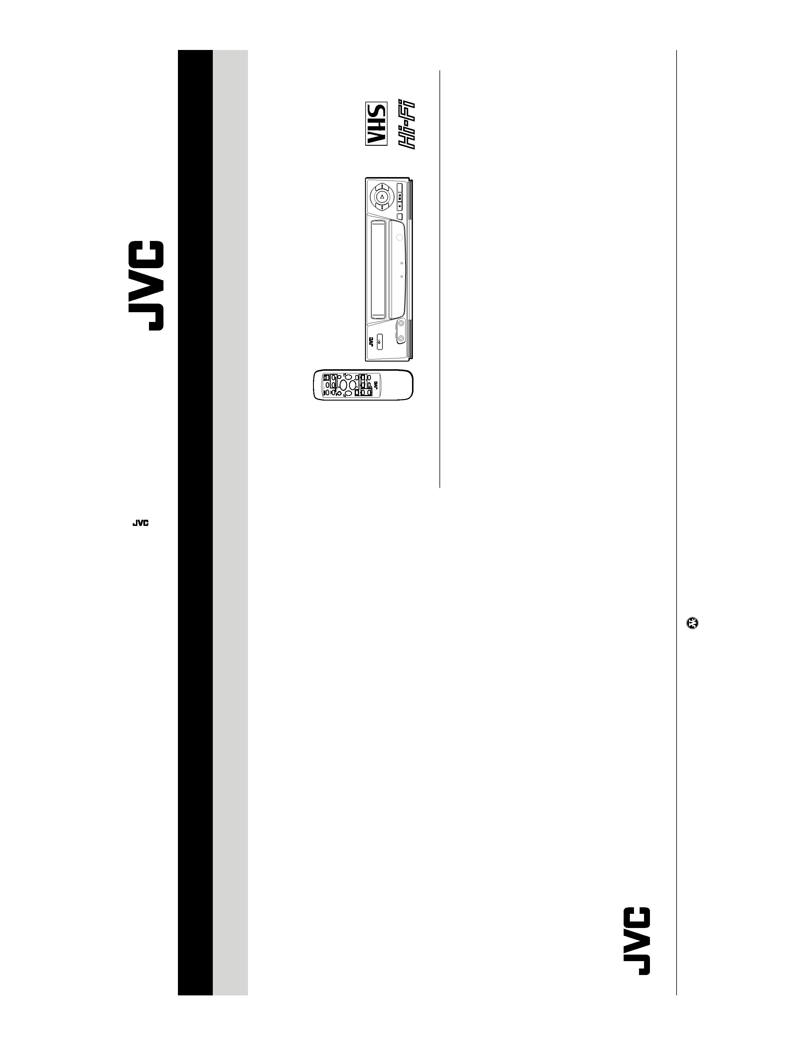
HR-P54A/P100A/P185EE
SPECIFICATIONS (The specifications shown pertain specifically to the model HR-P500K/P100A)
VIDEO CASSETTE PLAYER
Printed in Japan
VICTOR COMPANY OF JAPAN, LIMITED
VIDEO DIVISION
S40894
This service manual is printed on 100% recycled paper.
COPYRIGHT © 2000 VICTOR COMPANY OF JAPAN, LTD.
HR-P54A/P100A/P185EE
No.
82828
PAL NTSC
Hi-Fi KARAOKE MULTI 6HEAD
TAPE POSITION ON SCREEN AUTO VOLTAGE B.E.S.T. PICTURE
PAL/MESECAM/NTSC3.58/4.43
NTSC PLAYBACK ON PAL TV
MULTI SYSTEM
SUPER
HEAD CLEANER
Hi-Fi Karaoke
STANDBY/ON
MIC
2
1
POWER-ON
STANDBY/REC
OSD
SP/LP/EP
PAL NTSC
LP00000-000
+
+
TV/VCR
0000/X
PLAY
FF
REW
STOP
REC
VCP/TV
TV PR
TV
OK/OSD
MENU
PAUSE
TV
AUTO
TRACKING +
Format ................................. VHS Standard
Video recording system ....... Rotary, slant azimuth helical scan
system
Rotary heads ....................... [HR-P500K]
4 video heads
[HR-P100A]
2 video heads
RF output ............................ System B/G, D/K type modulation
UHF ch 32 40 adjustable (preset ch 36)
Recording (line input) .......... PAL, SECAM (MESECAM tape)
NTSC 3.58, NTSC 4.43
Playback (line output) ......... PAL, SECAM (MESECAM tape)
NTSC 3.58
NTSC 4.43
Simulated PAL (NTSC tape)
Video
Line input level .................. 0.5 2.0 Vp-p/75 ohms, unbalanced
Line output level ............... 1.0 Vp-p/75 ohms, unbalanced
S/N ratio ............................ More than 45 dB
Horizontal resolution ......... More than 250 lines
(PAL/MESECAM)
More than 220 lines (NTSC)
Audio
Line input level .................. 8 dBs/50 k ohms, unbalanced
Line output level ............... 8 dBs/1 k ohm, unbalanced
Frequency response ......... 70 Hz to 10,000 Hz (Normal)
[HR-P500K]
20 Hz to 20,000 Hz (Hi-Fi audio)
Power requirements
Rating ............................... AC 110 V 240 V, 50 Hz / 60 Hz
Operating .......................... AC 90 V 260 V, 50 Hz / 60 Hz
Power consumption ............ [HR-P500K]
14 W
[HR-P100A]
13 W
Operation temperature ........ 5°C to 40°C
Dimensions ......................... 360 mm (W)
× 94 mm (H) × 279 mm (D)
Weight ................................. 3.2 kg
Standard accessories
Remote control unit ............. 1
Batteries for remote control . 2
RF antenna cable ................ 1
Microphone (HR-P500K only) 1
Conversion plug .................. 1
· Design and specifications subject to change without notice.

Important Safety Precautions
INSTRUCTIONS
1. DISASSEMBLY
1.1 DISASSEMBLY FLOW CHART ............................................ 1-1
1.2 HOW TO READ THE DISASSEMBLY AND ASSEMBLY ...... 1-1
1.3 DISASSEMBLY/ASSEMBLY METHOD ................................ 1-1
1.4 SERVICE POSITION ............................................................ 1-4
1.4.1 How to take out the Mechanism and Main board
assemblies ...................................................................... 1-4
1.5 MECHANISM SERVICE MODE ............................................ 1-5
1.5.1 How to set the "MECHANISM SERVICE MODE" ........... 1-5
1.6 EMERGENCY DISPLAY FUNCTION ................................... 1-6
1.6.1 Displaying the emergency information ............................ 1-6
1.6.2 Clearing the emergency history ....................................... 1-6
1.6.3 Emergency content description ....................................... 1-7
1.6.4 Emergency detail information 1 ....................................... 1-8
1.6.5 Emergency detail information 2 ....................................... 1-9
2. MECHANISM ADJUSTMENT
2.1 BEFORE STARTING REPAIR AND ADJUSTMENT ............. 2-1
2.1.1 Precautions ..................................................................... 2-1
2.1.2 Checking for Proper Mechanical Operations ................... 2-1
2.1.3 Manually Removing the Cassette Tape ........................... 2-1
2.1.4 Jigs and Tools Required for Adjustment .......................... 2-2
2.1.5 Maintenance and Inspection ........................................... 2-3
2.2 REPLACEMENT OF MAJOR PARTS ................................... 2-6
2.2.1 Before Starting Disassembling
(Phase matching between mechanical parts) ................. 2-6
2.2.2 How to Set the Mechanism Assembling Mode ................ 2-6
2.2.3 Cassette Holder Assembly .............................................. 2-6
2.2.4 Pinch Roller Arm Assembly ............................................. 2-8
2.2.5 Guide Arm Assembly and Press Lever Assembly ........... 2-8
2.2.6 Audio Control Head ......................................................... 2-8
2.2.7 Loading Motor ................................................................. 2-8
2.2.8 Capstan Motor ................................................................. 2-9
2.2.9 Pole Base Assembly (supply or take-up side) ................. 2-9
2.2.10 Rotary Encoder ........................................................... 2-10
2.2.11 Clutch Unit .................................................................. 2-10
2.2.12 Change Lever Assembly, Direct Gear, Clutch Gear and
Coupling Gear ............................................................. 2-10
2.2.13 Link Lever .................................................................... 2-11
2.2.14 Cassette Gear, Control Cam and Worm Gear ............. 2-11
2.2.15 Control Plate ................................................................ 2-11
2.2.16 Loading Arm Gear (supply or take-up side) and
Loading Arm Gear Shaft ............................................. 2-12
2.2.17 Take-up Lever, Take-up Head and Control Plate Guide . 2-13
2.2.18 Capstan Brake Assembly ............................................ 2-13
2.2.19 Sub Brake Assembly (take-up side) ............................ 2-13
2.2.20 Main Brake Assembly (take-up side), Reel Disk (take-up side)
and Main Brake Assembly (supply side) ................................. 2-13
2.2.21 Tension Brake Assembly, Reel Disk (supply side) and
Tension Arm Assembly ................................................ 2-14
2.2.22 Idler Lever, Idler Arm Assembly .................................. 2-14
TABLE OF CONTENTS
Section
Title
Page
Section
Title
Page
2.2.23 Stator Assembly .......................................................... 2-14
2.2.24 Rotor Assembly ........................................................... 2-14
2.2.25 Upper Drum Assembly ................................................ 2-15
2.3 COMPATIBILITY ADJUSTMENT ........................................ 2-16
2.3.1 Checking/Adjustment of FM Waveform Linearity .......... 2-16
2.3.2 Checking/Adjustment of the Height and Tilt of the
Audio Control Head ....................................................... 2-17
2.3.3 Checking/Adjustment of the Audio Control Head Phase
(X-Value) ....................................................................... 2-17
2.3.4 Checking/Adjustment of the Standard Tracking Preset . 2-18
2.3.5 Checking/Adjustment of the Tension Pole Position ....... 2-18
3. ELECTRICAL ADJUSTMENT
3.1 PRECAUTION ...................................................................... 3-1
3.1.1 Required test equipments ............................................... 3-1
3.1.2 Required adjustment tools ............................................... 3-1
3.1.3 Color (colour) bar signal,Color (colour) bar pattern ......... 3-1
3.1.4 Switch settings and standard precautions ....................... 3-1
3.2 SERVO CIRCUIT .................................................................. 3-2
3.2.1 Switching point ................................................................ 3-2
3.2.2 Slow tracking preset ........................................................ 3-2
3.3 VIDEO CIRCUIT ................................................................... 3-2
3.3.1 AUTO PICTURE initial setting ......................................... 3-2
4. CHARTS AND DIAGRAMS
NOTES OF SCHEMATIC DIAGRAM .......................................... 4-1
CIRCUIT BOARD NOTES ........................................................... 4-2
4.1 BOARD INTERCONNECTIONS ........................................... 4-3
4.2 VIDEO/N.AUDIO/TUNER SCHEMATIC DIAGRAM .............. 4-5
4.3 SYSTEM CONTROL SCHEMATIC DIAGRAM ..................... 4-7
4.4 SWITCHING REGULATOR SCHEMATIC DIAGRAM ........... 4-9
4.5 FRONT AND LED SCHEMATIC DIAGRAMS ......................4-11
4.6 MAIN AND LED CIRCUIT BOARDS ................................... 4-13
4.7 REMOTE CONTROL SCHEMATIC DIAGRAM .................. 4-19
4.8 WAVEFORMS ..................................................................... 4-20
4.9 VOLTAGE CHARTS ............................................................ 4-21
4.10 CPU PIN FUNCTION ....................................................... 4-22
4.11 SYSTEM CONTROL BLOCK DIAGRAM ......................... 4-23
4.12 VIDEO BLOCK DIAGRAM ............................................... 4-25
4.13 AUDIO BLOCK DIAGRAM ............................................... 4-27
5. PARTS LIST
5.1 PACKING AND ACCESSORY ASSEMBLY <M1> ............... 5-1
5.2 FINAL ASSEMBLY <M2> ...................................................... 5-2
5.3 MECHANISM ASSEMBLY <M4> ......................................... 5-4
5.4 ELECTRICAL PARTS LIST ................................................... 5-6
MAIN BOARD ASSEMBLY <03> ............................................... 5-6
LED BOARD ASSEMBLY <09> ................................................. 5-9
AUDIO CONTROL HEAD BOARD ASSEMBLY <12> ............. 5-10
LOADING MOTOR BOARD ASSEMBLY <55> ....................... 5-10
The following table lists the differing points between Models (HR-P54A, HR-P100A and HR-P185EE) in this series.
HR-P54A
HR-P100A
HR-P185EE
RECORDING & PLAYBACK SPEED
SP/LP/EP
SP/LP/EP
SP
POWER PLUG
CEE
SASO
CEE
ACCESSORY (INST. LANGUAGE)
ENG, RUS
ENG, RUS, ARA
RUS
ACCESSORY (CONVERSION PLUG)
NOT USED
SASO
CEE
NOT USED
Important Safety Precautions
Prior to shipment from the factory, JVC products are strictly inspected to conform with the recognized product safety and electrical codes of the
countries in which they are to be sold. However, in order to maintain such compliance, it is equally important to implement the following precautions
when a set is being serviced.
Fig.1
1. Locations requiring special caution are denoted by labels and in-
scriptions on the cabinet, chassis and certain parts of the product.
When performing service, be sure to read and comply with these
and other cautionary notices appearing in the operation and serv-
ice manuals.
2. Parts identified by the
symbol and shaded (
) parts are
critical for safety.
Replace only with specified part numbers.
Note: Parts in this category also include those specified to com-
ply with X-ray emission standards for products using
cathode ray tubes and those specified for compliance
with various regulations regarding spurious radiation
emission.
3. Fuse replacement caution notice.
Caution for continued protection against fire hazard.
Replace only with same type and rated fuse(s) as specified.
4. Use specified internal wiring. Note especially:
1) Wires covered with PVC tubing
2) Double insulated wires
3) High voltage leads
5. Use specified insulating materials for hazardous live parts. Note
especially:
1) Insulation Tape
3) Spacers
5) Barrier
2) PVC tubing
4) Insulation sheets for transistors
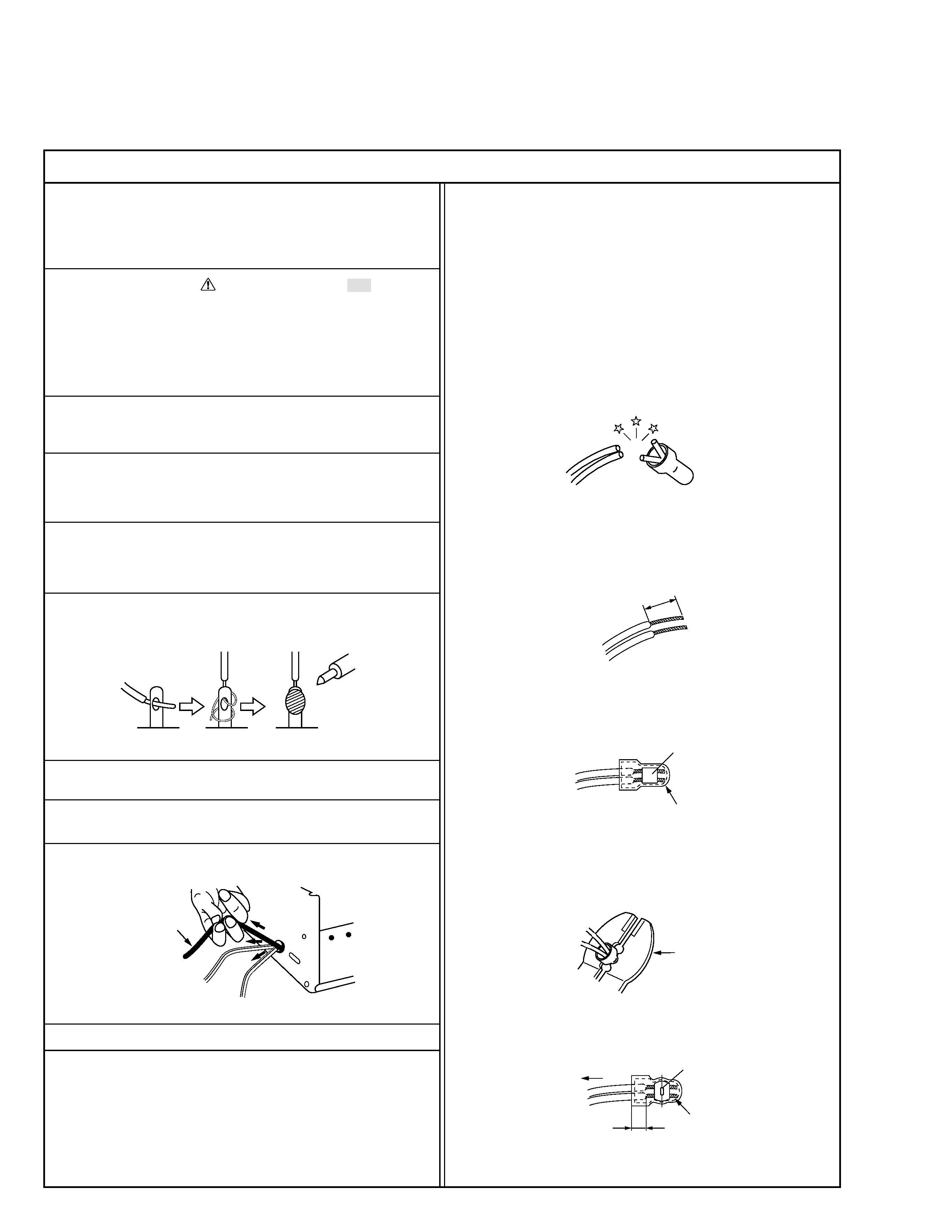
6. When replacing AC primary side components (transformers, power
cords, noise blocking capacitors, etc.) wrap ends of wires securely
about the terminals before soldering.
Power cord
Fig.2
10. Also check areas surrounding repaired locations.
11. Products using cathode ray tubes (CRTs)
In regard to such products, the cathode ray tubes themselves, the
high voltage circuits, and related circuits are specified for compli-
ance with recognized codes pertaining to X-ray emission.
Consequently, when servicing these products, replace the cath-
ode ray tubes and other parts with only the specified parts. Under
no circumstances attempt to modify these circuits.
Unauthorized modification can increase the high voltage value and
cause X-ray emission from the cathode ray tube.
12. Crimp type wire connector
In such cases as when replacing the power transformer in sets
where the connections between the power cord and power trans-
former primary lead wires are performed using crimp type connec-
tors, if replacing the connectors is unavoidable, in order to prevent
safety hazards, perform carefully and precisely according to the
following steps.
1) Connector part number : E03830-001
2) Required tool : Connector crimping tool of the proper type which
will not damage insulated parts.
3) Replacement procedure
(1) Remove the old connector by cutting the wires at a point
close to the connector.
Important : Do not reuse a connector (discard it).
Fig.7
cut close to connector
Fig.3
(2) Strip about 15 mm of the insulation from the ends of the
wires. If the wires are stranded, twist the strands to avoid
frayed conductors.
15 mm
Fig.4
(3) Align the lengths of the wires to be connected. Insert the
wires fully into the connector.
Connector
Metal sleeve
Fig.5
(4) As shown in Fig.6, use the crimping tool to crimp the metal
sleeve at the center position. Be sure to crimp fully to the
complete closure of the tool.
1
·Precautions during Servicing
7. Observe that wires do not contact heat producing parts (heatsinks,
oxide metal film resistors, fusible resistors, etc.)
8. Check that replaced wires do not contact sharp edged or pointed
parts.
9. When a power cord has been replaced, check that 10-15 kg of
force in any direction will not loosen it.
1.2
5
2.0
5.5
Crimping tool
Fig.6
(5) Check the four points noted in Fig.7.
Not easily pulled free
Crimped at approx. center
of metal sleeve
Conductors extended
Wire insulation recessed
more than 4 mm
S40888-01
·Safety Check after Servicing
Examine the area surrounding the repaired location for damage or deterioration. Observe that screws, parts and wires have been returned
to original positions, Afterwards, perform the following tests and confirm the specified values in order to verify compliance with safety
standards.
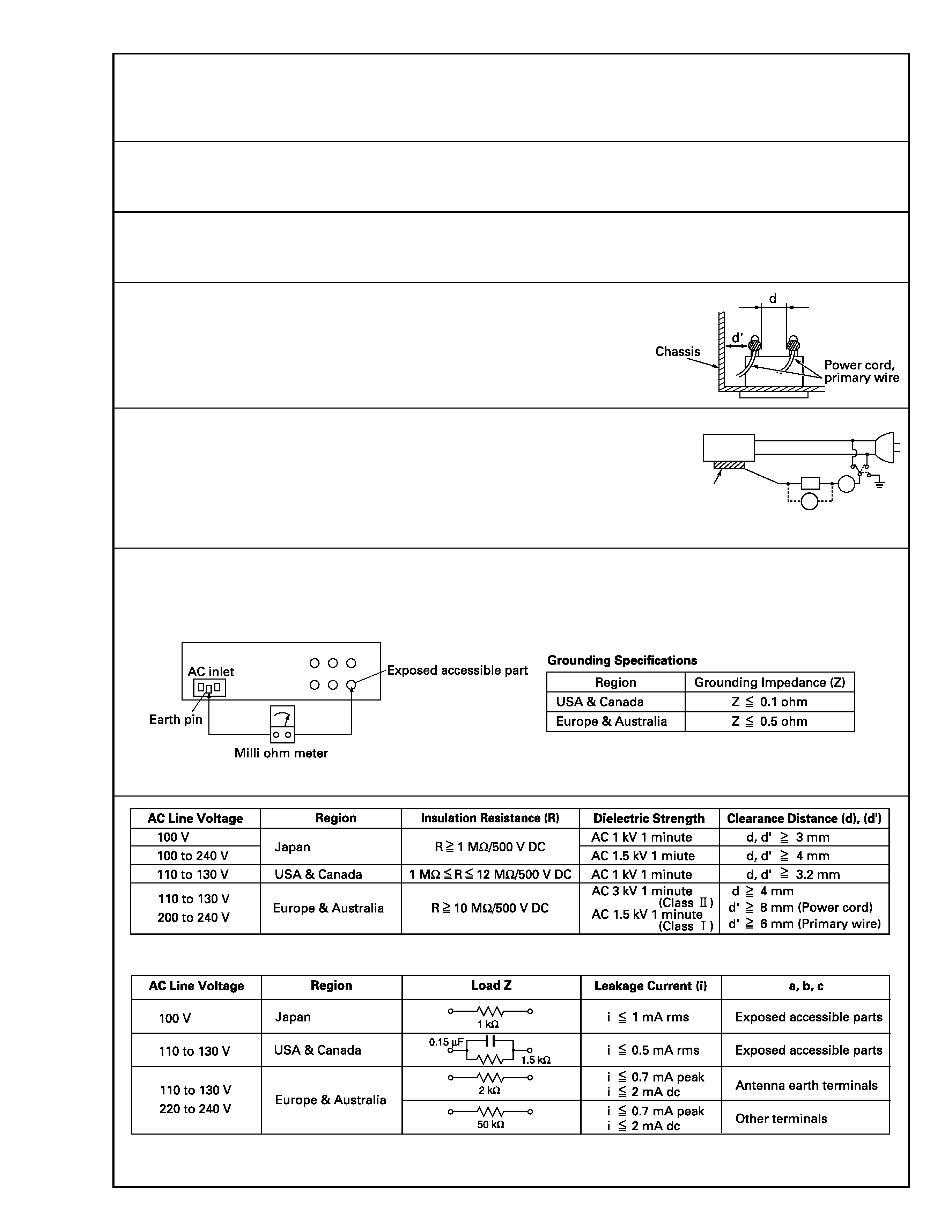
1. Insulation resistance test
Confirm the specified insulation resistance or greater between power cord plug prongs and exter-
nally exposed parts of the set (RF terminals, antenna terminals, video and audio input and output
terminals, microphone jacks, earphone jacks, etc.). See table 1 below.
2. Dielectric strength test
Confirm specified dielectric strength or greater between power cord plug prongs and exposed acces-
sible parts of the set (RF terminals, antenna terminals, video and audio input and output terminals,
microphone jacks, earphone jacks, etc.). See table 1 below.
3. Clearance distance
When replacing primary circuit components, confirm specified clearance distance (d), (d') be-
tween soldered terminals, and between terminals and surrounding metallic parts. See table 1
below.
4. Leakage current test
Confirm specified or lower leakage current between earth ground/power cord plug prongs and
externally exposed accessible parts (RF terminals, antenna terminals, video and audio input and
output terminals, microphone jacks, earphone jacks, etc.).
Measuring Method : (Power ON)
Insert load Z between earth ground/power cord plug prongs and externally exposed accessible
parts. Use an AC voltmeter to measure across both terminals of load Z. See figure 9 and following
table 2.
5. Grounding (Class 1 model only)
Confirm specified or lower grounding impedance between earth pin in AC inlet and externally exposed accessible parts (Video in, Video out,
Audio in, Audio out or Fixing screw etc.).
Measuring Method:
Connect milli ohm meter between earth pin in AC inlet and exposed accessible parts. See figure 10 and grounding specifications.
Fig. 10
Fig. 9
Fig. 8
Table 1 Specifications for each region
Table 2 Leakage current specifications for each region
Note: These tables are unofficial and for reference only. Be sure to confirm the precise values for your particular country and locality.
2
S40888-01
ab
c
V
A
Externally
exposed
accessible part
Z
