SERVICE MANUAL
No.82904
January 2002
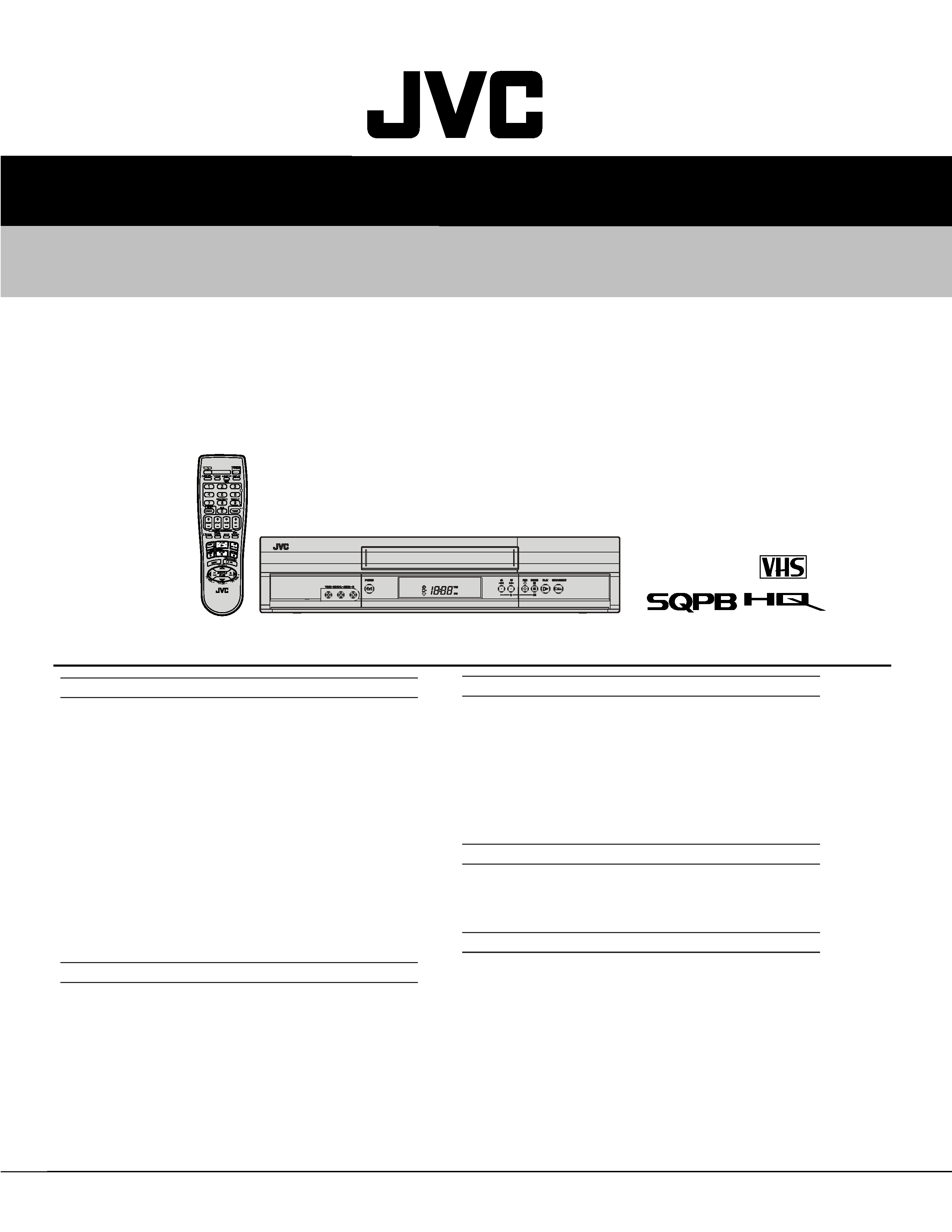
HR-J691U/J694U/J695U/J698U
VIDEO CASSETTE RECORDER
SPECIFICATIONS (The specifications shown pertain specifically to the model HR-J698U.)
This service manual is printed on 100% recycled paper.
COPYRIGHT © 2002 VICTOR COMPANY OF JAPAN, LTD
Specifications shown are for SP mode unless specified otherwise.
E. & O.E. Design and specifications subject to change without
notice.
GENERAL
Power requirement
: AC 120 Vd, 60 Hz
Power consumption
Power on
: 13 W
Power off
: 1.5 W
Temperature
Operating
: 5
°C to 40°C (41°F to 104°F)
Storage
: 20
°C to 60°C (4°F to 140°F)
Operating position
: Horizontal only
Dimensions (W x H x D) : 435 mm x 94 mm x 247 mm
(17-1/4" x 3-3/4" x 9-3/4")
Weight
: 2.7 kg (6.6 lbs)
Format
: VHS NTSC standard
Maximum recording time
SP
: 210 min. with ST-210 video cassette
EP
: 630 min. with ST-210 video cassette
VIDEO/AUDIO
Signal system
: NTSC-type color signal and EIA
monochrome signal, 525 lines/
60 fields
Recording/Playback
system
: DA-4 (Double Azimuth) head helical
scan system
Signal-to-noise ratio
: 45 dB
Horizontal resolution
: 230 lines
Frequency range
Normal audio
: 70 Hz to 10,000 Hz
Hi-Fi audio
: 20 Hz to 20,000 Hz
Input/Output
: RCA connectors (IN x 1, OUT x 1)
TUNER
Tuning system
: Frequency-synthesized tuner
Channel coverage
VHF
: Channels 213
UHF
: Channels 1469
CATV
: 113 Channels
RF output
: Channel 3, 4 or (off) (preset to
Channel 3 when shipped) 75 ohms,
unbalanced
TIMER
Clock reference
: Quartz
Program capacity
: 1-year programmable timer/
8programs
ACCESSORIES
Provided accessories
: RF cable (F-type),
Infrared remote control unit,
"AA" battery x 2
HR-J691U/J691U(C)/J694U/J695U(C)/J698U(C)
V15D1

TABLE OF CONTENTS
Section
Title
Page
Section
Title
Page
Important Safety Precautions
INSTRUCTIONS
1. DISASSEMBLY
1.1 Manually removing the cassette tape .......................... 1-1
1.2 Removing the major parts ............................................ 1-2
1.2.1 How to read the procedure table ............................. 1-2
1.2.2 Disassembly/assembly method .............................. 1-2
1.3 Emergency display function ......................................... 1-4
1.3.1 Displaying the EMG information ............................. 1-4
1.3.2 Clearing the EMG history ........................................ 1-4
1.3.3 Details of the OSD display in the EMG display mode ... 1-5
1.3.4 EMG content description ......................................... 1-6
1.3.5 EMG detail information<1> ..................................... 1-7
1.3.6 EMG detail information<2> ..................................... 1-8
1.3.7 EMG detail information<3> ..................................... 1-8
1.4 Service position ............................................................ 1-9
1.4.1 How to set the "Service position" ............................ 1-9
1.5 Jig RCU mode .............................................................. 1-9
1.5.1 Setting the Jig RCU mode ...................................... 1-9
1.5.2 Setting the User RCU mode ................................... 1-9
1.6 Mechanism service mode ............................................ 1-9
1.6.1 How to set the "Mechanism service mode" ............. 1-9
1.6.2 How to exit from the "Mechanism service mode" .... 1-9
1.7 Maintenance and inspection ...................................... 1-10
1.7.1 Cleaning ................................................................ 1-10
1.7.2 Lubrication ............................................................ 1-10
1.7.3 Suggested servicing schedule for main components ... 1-10
2. DISASSEMBLING/ASSEMBLING OF MECHANISM
1. Before disassembling/assembling ................................. 2-1
1.1 Notes ........................................................................... 2-1
1.2 Mechanism operation check ....................................... 2-1
1.3 Setting the mechanism assembling mode .................. 2-1
1.4 Layout of the main mechanism parts .......................... 2-2
1.5 Disassembling procedure table ................................... 2-3
2. Replacement of the main mechanism parts ................... 2-4
2.1 Cassette holder ........................................................... 2-4
2.2 A/C head ..................................................................... 2-5
2.3 Guide arm, pinch roller arm ........................................ 2-6
2.4 Idler arm, idler gear 1/2 ............................................... 2-6
2.5 Main brake(T), brake lever, tension arm,
reel disk(S/T), Rec safety lever ................................... 2-6
2.6 Press lever, control cam, capstan brake assembly,
loading motor assembly .............................................. 2-7
2.7 Capstan motor, load gear, control plate ...................... 2-8
2.8 Clutch unit assembly, direct gear ................................ 2-9
3. Mechanism timing chart ............................................... 2-10
3. ADJUSTMENT
3.1 Precaution .................................................................... 3-1
3.1.1 Required test equipments ....................................... 3-1
3.1.2 Required adjustment tools ...................................... 3-1
3.1.3 Color(colour) bar signal, color(colour) bar pattern .. 3-1
3.1.4 Switch settings ........................................................ 3-1
3.1.5 Manual tracking mode (Auto tracking ON/OFF) setting ... 3-1
3.2 Mechanism compatibility adjustment ........................... 3-2
3.2.1 Tension pole position ............................................... 3-2
3.2.2 FM waveform linearity ............................................. 3-2
3.2.3 Height and tilt of the A/C head ................................ 3-3
3.2.4 A/C head phase(X-value) ........................................ 3-3
3.3 Electrical Adjustment .................................................... 3-4
3.3.1 Servo circuit ............................................................ 3-4
3.3.1.1 Switching point ................................................... 3-4
The following table lists the differing points between models HR-J691U, J691U(C), J694U, J695U(C) and J698U(C).
MODEL
HR-J691U
ITEM
BODY COLOR
BLACK
PURE-SILVER
BLACK
RCU ILUMINATION FUNCTION
NOT USED
USED
CHILD LOCK
NOT USED
USED
NOT USED
4. CHARTS AND DIAGRAMS
4.1 BOARD INTERCONNECTIONS ................................ 4-3
4.2 MAIN(VIDEO/N.AUDIO) SCHEMATIC DIAGRAM ..... 4-5
4.3 MAIN(SYSCON) SCHEMATIC DIAGRAM ................. 4-7
4.4 MAIN(SW.REG) SCHEMATIC DIAGRAM .................. 4-9
4.5 MAIN(TUNER) SCHEMATIC DIAGRAM .................. 4-11
4.6 MAIN(FMA/DEMOD) SCHEMATIC DIAGRAM ........ 4-13
4.7 MAIN(FRONT) SCHEMATIC DIAGRAM .................. 4-15
4.8 MAIN(TERMINAL) SCHEMATIC DIAGRAM ............ 4-17
4.9 MAIN CIRCUIT BOARD ........................................... 4-19
4.10 REMOTE CONTROLLER SCEMATIC DIAGRAM . 4-21
4.11 FDP GRID ASSIGNMENT AND ANODE CONNECTION . 4-21
4.12 WAVEFORMS ........................................................ 4-22
4.13 VOLTAGE CHARTS ............................................... 4-23
4.14 CPU PIN FUNCTION ............................................. 4-24
4.15 SYSTEM CONTROL BLOCK DIAGRAM ............... 4-25
4.16 VIDEO BLOCK DIAGRAM ..................................... 4-27
4.17 AUDIO BLOCK DIAGRAM ..................................... 4-29
5. PARTS LIST
5.1 PACKING AND ACCESSORY ASSEMBLY<M1> ........ 5-1
5.2 FINAL ASSEMBLY<M2> .............................................. 5-2
5.3 MECHANISM ASSEMBLY<M4> .................................. 5-4
5.4 ELECTRICAL PARTS LIST .......................................... 5-6
MAIN BOARD ASSEMBLY<03> ...................................... 5-6
A/C HEAD BOARD ASSEMBLY<12> ............................ 5-10
LOADING MOTOR BOARD ASSEMBLY<55> ............... 5-10
HR-J691U(C)
HR-J694U
HR-J695U(C)
HR-698U(C)
Notes: Mark
is same as left.
Important Safety Precautions
Prior to shipment from the factory, JVC products are strictly inspected to conform with the recognized product safety and electrical codes
of the countries in which they are to be sold. However, in order to maintain such compliance, it is equally important to implement the
following precautions when a set is being serviced.
Fig.1
1. Locations requiring special caution are denoted by labels and
inscriptions on the cabinet, chassis and certain parts of the
product. When performing service, be sure to read and com-
ply with these and other cautionary notices appearing in the
operation and service manuals.
2. Parts identified by the
symbol and shaded (
) parts are
critical for safety.
Replace only with specified part numbers.
Note: Parts in this category also include those specified to com-
ply with X-ray emission standards for products using
cathode ray tubes and those specified for compliance
with various regulations regarding spurious radiation
emission.
3. Fuse replacement caution notice.
Caution for continued protection against fire hazard.
Replace only with same type and rated fuse(s) as specified.
4. Use specified internal wiring. Note especially:
1) Wires covered with PVC tubing
2) Double insulated wires
3) High voltage leads
5. Use specified insulating materials for hazardous live parts.
Note especially:
1) Insulation Tape
3) Spacers
5) Barrier
2) PVC tubing
4) Insulation sheets for transistors
6. When replacing AC primary side components (transformers,
power cords, noise blocking capacitors, etc.) wrap ends of
wires securely about the terminals before soldering.
Power cord
Fig.2
10. Also check areas surrounding repaired locations.
11. Products using cathode ray tubes (CRTs)
In regard to such products, the cathode ray tubes themselves,
the high voltage circuits, and related circuits are specified for
compliance with recognized codes pertaining to X-ray emission.
Consequently, when servicing these products, replace the cath-
ode ray tubes and other parts with only the specified parts.
Under no circumstances attempt to modify these circuits.
Unauthorized modification can increase the high voltage value
and cause X-ray emission from the cathode ray tube.
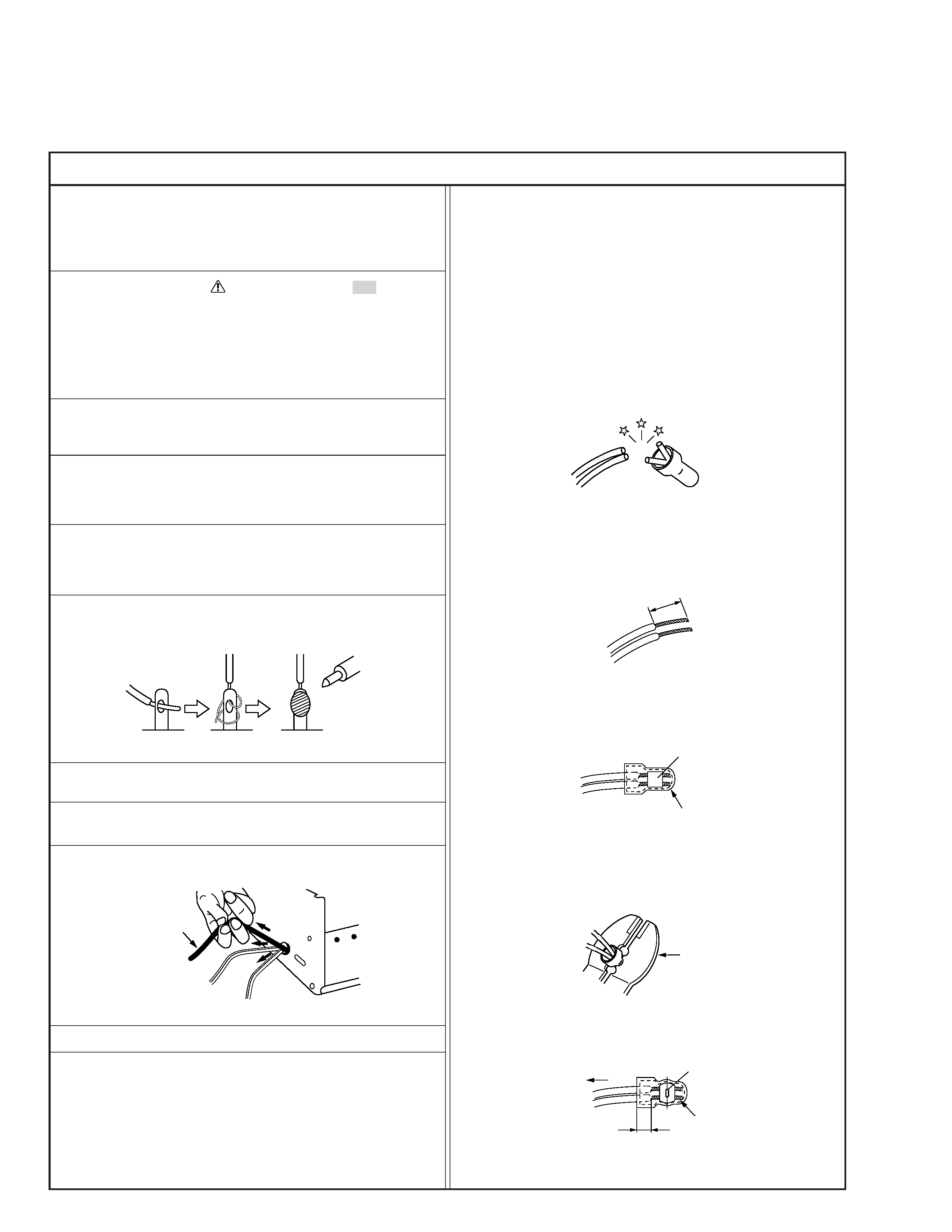
12. Crimp type wire connector
In such cases as when replacing the power transformer in sets
where the connections between the power cord and power
transformer primary lead wires are performed using crimp type
connectors, if replacing the connectors is unavoidable, in or-
der to prevent safety hazards, perform carefully and precisely
according to the following steps.
1) Connector part number : E03830-001
2) Required tool : Connector crimping tool of the proper type
which will not damage insulated parts.
3) Replacement procedure
(1) Remove the old connector by cutting the wires at a point
close to the connector.
Important : Do not reuse a connector (discard it).
Fig.7
cut close to connector
Fig.3
(2) Strip about 15 mm of the insulation from the ends of
the wires. If the wires are stranded, twist the strands to
avoid frayed conductors.
15 mm
Fig.4
(3) Align the lengths of the wires to be connected. Insert
the wires fully into the connector.
Connector
Metal sleeve
Fig.5
(4) As shown in Fig.6, use the crimping tool to crimp the
metal sleeve at the center position. Be sure to crimp fully
to the complete closure of the tool.
1
Precautions during Servicing
7. Observe that wires do not contact heat producing parts
(heatsinks, oxide metal film resistors, fusible resistors, etc.)
8. Check that replaced wires do not contact sharp edged or
pointed parts.
9. When a power cord has been replaced, check that 10-15 kg of
force in any direction will not loosen it.
1.25
2.0
5.5
Crimping tool
Fig.6
(5) Check the four points noted in Fig.7.
Not easily pulled free
Crimped at approx. center
of metal sleeve
Conductors extended
Wire insulation recessed
more than 4 mm
S40888-01
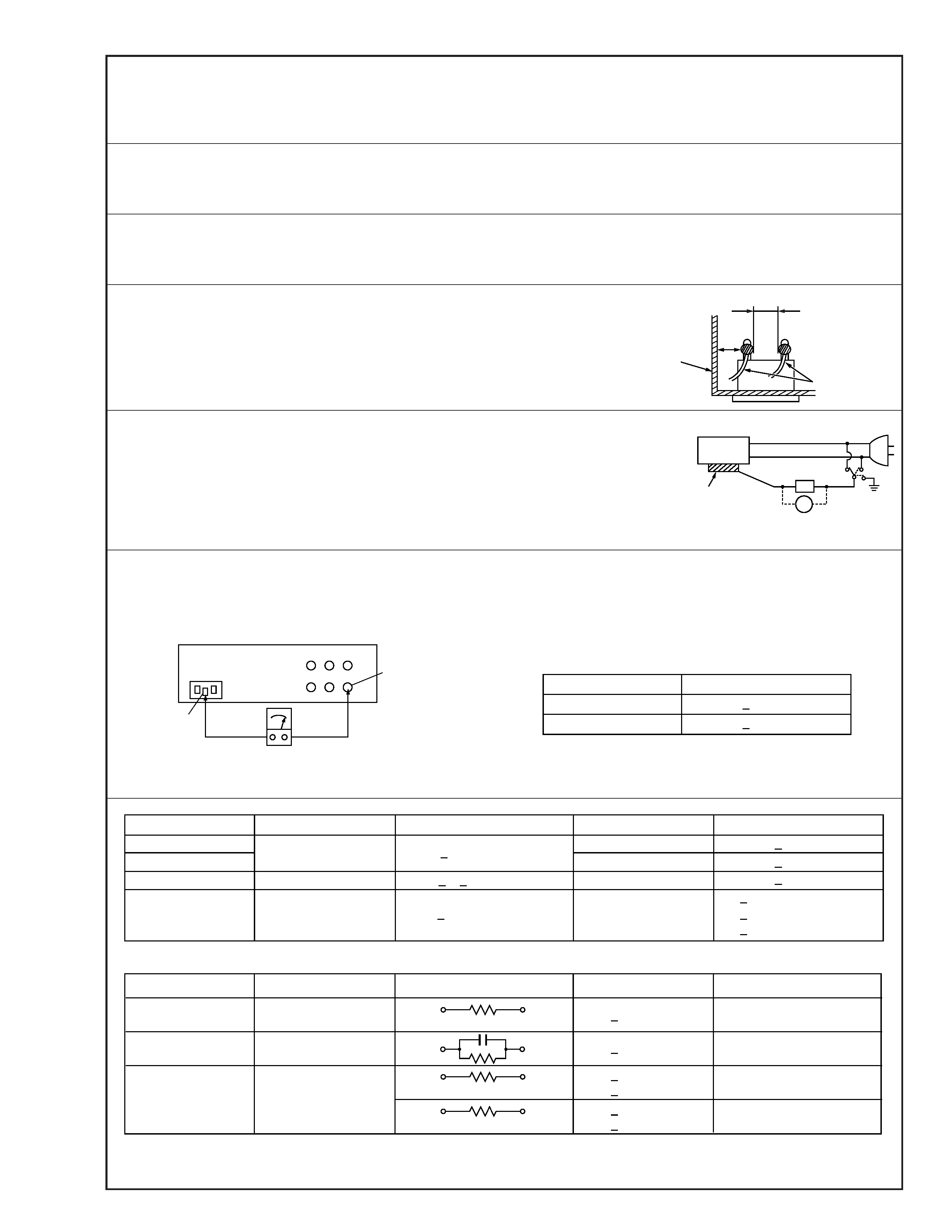
Safety Check after Servicing
Examine the area surrounding the repaired location for damage or deterioration. Observe that screws, parts and wires have been
returned to original positions, Afterwards, perform the following tests and confirm the specified values in order to verify compli-
ance with safety standards.
1. Insulation resistance test
Confirm the specified insulation resistance or greater between power cord plug prongs and
externally exposed parts of the set (RF terminals, antenna terminals, video and audio input
and output terminals, microphone jacks, earphone jacks, etc.). See table 1 below.
2. Dielectric strength test
Confirm specified dielectric strength or greater between power cord plug prongs and exposed
accessible parts of the set (RF terminals, antenna terminals, video and audio input and output
terminals, microphone jacks, earphone jacks, etc.). See table 1 below.
3. Clearance distance
When replacing primary circuit components, confirm specified clearance distance (d), (d') be-
tween soldered terminals, and between terminals and surrounding metallic parts. See table 1
below.
4. Leakage current test
Confirm specified or lower leakage current between earth ground/power cord plug prongs
and externally exposed accessible parts (RF terminals, antenna terminals, video and audio
input and output terminals, microphone jacks, earphone jacks, etc.).
Measuring Method : (Power ON)
Insert load Z between earth ground/power cord plug prongs and externally exposed accessi-
ble parts. Use an AC voltmeter to measure across both terminals of load Z. See figure 9 and
following table 2.
5. Grounding (Class 1 model only)
Confirm specified or lower grounding impedance between earth pin in AC inlet and externally exposed accessible parts (Video in,
Video out, Audio in, Audio out or Fixing screw etc.).
Measuring Method:
Connect milli ohm meter between earth pin in AC inlet and exposed accessible parts. See figure 10 and grounding specifications.
d'
d
Chassis
Power cord,
primary wire
Region
USA & Canada
Europe & Australia
Grounding Impedance (Z)
Z
0.1 ohm
Z
0.5 ohm
AC inlet
Earth pin
Exposed accessible part
Milli ohm meter
Grounding Specifications
Fig. 10
ab
c
V
Externally
exposed
accessible part
Z
Fig. 9
Fig. 8
Clearance Distance (d), (d')
d, d'
3 mm
d, d'
4 mm
d, d'
3.2 mm
1 M
R 12 M/500 V DC
Dielectric Strength
AC 1 kV 1 minute
AC 1.5 kV 1 miute
AC 1 kV 1 minute
AC Line Voltage
100 V
100 to 240 V
110 to 130 V
110 to 130 V
200 to 240 V
Japan
USA & Canada
Europe & Australia
R
10 M
/500 V DC
Region
Insulation Resistance (R)
R
1 M
/500 V DC
AC 3 kV 1 minute
(Class
2)
AC 1.5 kV 1 minute
(Class
1)
d
4 mm
d'
8 mm (Power cord)
d'
6 mm (Primary wire)
Table 1 Specifications for each region
a, b, c
Leakage Current (i)
AC Line Voltage
100 V
110 to 130 V
110 to 130 V
220 to 240 V
Japan
USA & Canada
i
1 mA rms
Exposed accessible parts
Exposed accessible parts
Antenna earth terminals
Other terminals
i
0.5 mA rms
i
0.7 mA peak
i
2 mA dc
i
0.7 mA peak
i
2 mA dc
Europe & Australia
Region
Load Z
1 k
2 k
1.5 k
0.15
µF
50 k
Table 2 Leakage current specifications for each region
Note: These tables are unofficial and for reference only. Be sure to confirm the precise values for your particular country and locality.
2
S40888-01
1-1
SECTION 1
DISASSEMBLY
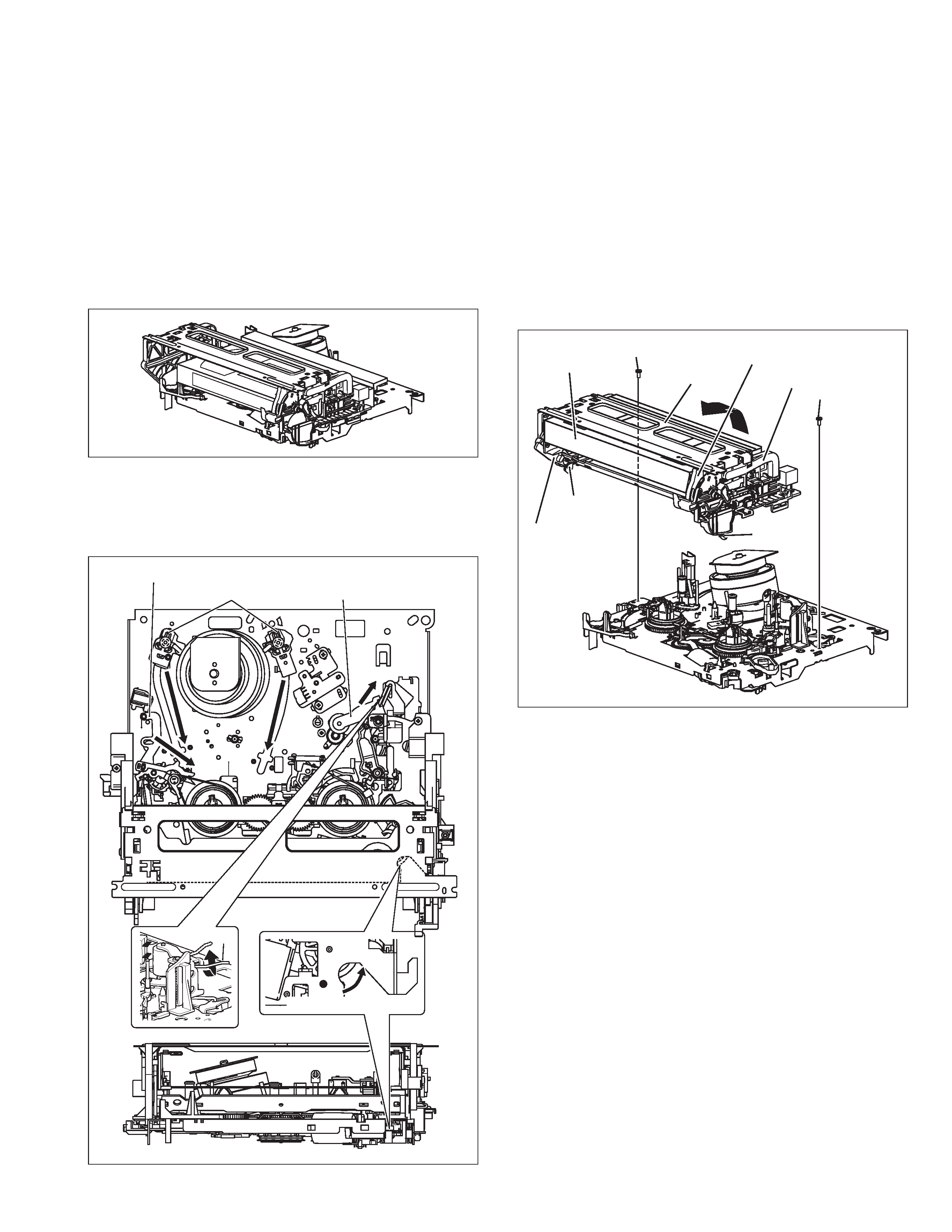
1.1 Manually removing the cassette tape
If you cannot remove the cassette tape which is loaded be-
cause of any electrical or mechanical failures, manually remove
it by taking the following steps.
(1) Unplug the power cord plug from the power outlet.
(2) Refer to the disassembly procedure of the VCR and perform
the disassembly of the major parts before removing the
mechanism assembly. (refer to Fig. 1-1a)
Fig. 1-1b
Fig. 1-1c
(3) Unload the pole base assembly by manually turning the gear
of the loading motor until the pole base assembly is hidden
behind the cassette lid. In doing so, hold the tape by the hand
to keep the slack away from any grease.
Fig. 1-1a
In case of mechanical failures, while keeping the tension
arm assembly free from tension, pull out the tape on the
pole base assembly. Take the spring(a) of the pinch
roller arm assembly off the hook, and detach it from the
tape.
(4) Remove the screw (a) of the side frame (L/R).
(5) Hold the slack tape and cassette cover together, lift the
cassette tape, top frame, cassette holder and side frames
(L, R) together from the rear and remove them by dis-
engaging the hooks (a) and (b).
(6) Take up the slack of the tape into the cassette. This com-
pletes removal of the cassette tape.
Pole base assembly
Tension arm assembly
Pinch roller arm assembly
Direction of unloading
Spring(a)
Screw(a)
Screw(a)
Top frame
Cassette tape
Cassette holder
Side frame(R)
Side frame(L)
Hook(a)
Hook(b)