HR-J635EA
VIDEO CASSETTE RECORDER
INSTRUCTIONS
PU30425-1947
PAL NTSC
SCE
NE FI
NDER
DISPLA
Y
OPERATE
PROG.
PLAY
STOP
CLOCK
DAILY (M-F)
AUX
C.RESET
CANCEL
TV
VOL.
TV
PROG.
TV/VIDEO
TV
VCR
TIMER
WEEKLY
A
12
45
3
6
8
0
7
9
B
MULTI BRAND
REMOTE CONTROL UNIT
REW
REC
FF
PAUSE
PUSH JOG
START
STOP
DATE
OK
/C.MEM
ORY
TV VOL.
6
q
FF
REW
STORE
OK
SHUTTLE
AUTO SP / LP
TIMER
START
A. DUB
WIDE
QUALITY
CHSET
R.A.EDIT
IN/OUT
VIDEO (MONO)L AUDIOR
OPERATE
COLOUR
SYSTEM
TV PROG /
JOG
WIDE
QUALITY
REC
TIMER
PLAY
NTSC
M
SP LP
ST BIL
+8
4
0
6
10
20dB
NORM
L
R
CONTENTS
SAFETY FIRST
2
Safety Precautions .................................... 2
INSTALLING YOUR NEW RECORDER
3
Basic Connections ................................... 3
Tune The TV To Your Video Recorder ...... 4
INITIAL SETTINGS
5
On-Screen Displays ................................. 5
Tuner Set .................................................. 6
Clock Set ................................................. 9
PLAYBACK
10
Basic Playback ....................................... 10
Playback Features .................................. 11
RECORDING
15
Basic Recording ..................................... 15
Recording Features ................................ 16
B.E.S.T. Picture System ........................... 18
TIMER RECORDING
20
G-Code Setup ........................................ 20
G-Code Timer Programming .................. 22
Regular Timer Programming .................. 24
Check And Cancel Programmes ......... 25
Auto SP/LP Timer ............................... 25
EDITING
26
Edit To Or From Another Video
Recorder ................................................ 26
Edit From A Camcorder ......................... 27
Random Assemble Editing ..................... 28
Audio Dubbing ...................................... 30
REMOTE CONTROL
31
Multi-Brand Remote Control .................. 31
INFORMATION ON MULTI-SYSTEM
COMPATIBILITY
32
TROUBLESHOOTING
34
QUESTIONS AND ANSWERS
36
INDEX
37
SPECIFICATIONS
Back cover
ENGLISH
2 EN
SAFETY FIRST
Safety Precautions
The rating plate and the safety caution are on the rear of the unit.
WARNING: DANGEROUS VOLTAGE INSIDE
WARNING: TO PREVENT FIRE OR SHOCK HAZARD, DO NOT EXPOSE THIS UNIT TO RAIN OR MOISTURE.
CAUTION
When you are not using the recorder for a long period of
time, it is recommended that you disconnect the power
cord from the mains outlet.
Dangerous voltage inside. Refer internal servicing to
qualified service personnel. To prevent electric shock or fire
hazard, remove the power cord from the mains outlet prior
to connecting or disconnecting any signal lead or aerial.
IMPORTANT
Please read the various precautions on this page before
installing or operating the recorder.
It should be noted that it may be unlawful to re-record
pre-recorded tapes, records, or discs without the consent
of the owner of copyright in the sound or video record-
ing, broadcast or cable programme and in any literary,
dramatic, musical, or artistic work embodied therein.
The OPERATE button does not completely shut off mains
power from the unit, but switches operating current on and off.
Video tapes recorded with this video recorder in the LP
(Long Play) mode cannot be played back on a single-speed
video recorder.
Only cassettes marked "VHS" can be used with this
videorecorder.
HQ VHS is compatible with existing VHS equipment.
G-Code is a trademark of Gemstar Development Corporation.
The G-Code system is manufactured under license from
Gemstar Development Corporation.
Failure to heed the following precautions may result in
damage to the recorder, remote control or video
cassette.
1. DO NOT place the recorder . . .
... in an environment prone to extreme temperatures or
humidity.
... in direct sunlight.
... in a dusty environment.
... in an environment where strong magnetic fields are
generated.
... on a surface that is unstable or subject to vibration.
2. DO NOT block the recorder's ventilation openings.
3. DO NOT place heavy objects on the recorder or remote
control.
4. DO NOT place anything which might spill on top of the
recorder or remote control.
5. AVOID violent shocks to the recorder during transport.
MOISTURE CONDENSATION
Moisture in the air will condense on the recorder when you
move it from a cold place to a warm place, or under extremely
humid conditions--just as water droplets form in the surface of
a glass filled with cold liquid. Moisture condensation on the
head drum will cause damage to the tape. In conditions where
condensation may occur, keep the recorder turned on for a few
hours to let the moisture dry.
ABOUT HEAD CLEANING
Accumulation of dirt and other particles on the video heads
may cause the playback picture to become blurred or inter-
rupted. Be sure to contact your nearest JVC dealer if such
troubles occur.
PAL NTSC
EN
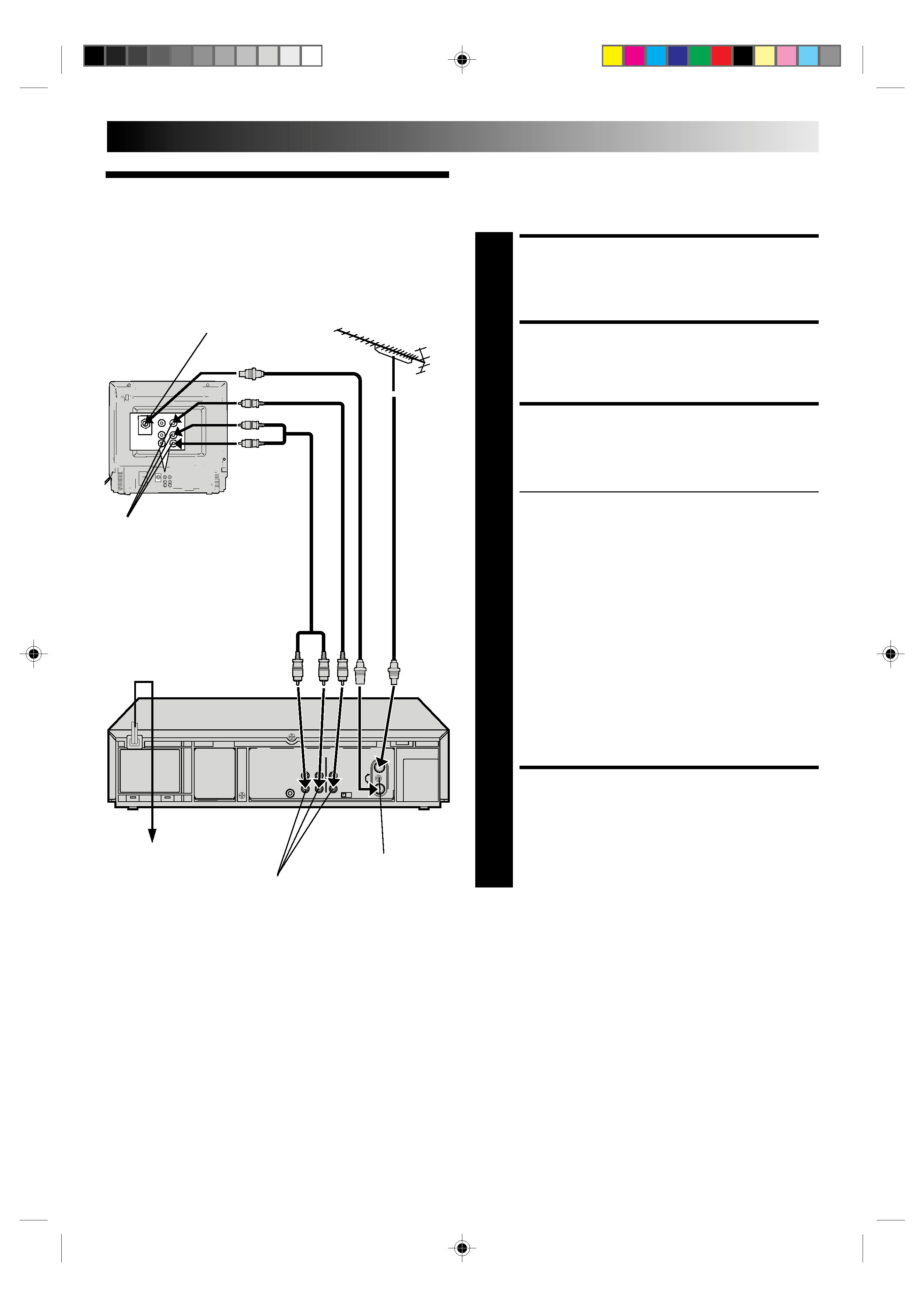
3
Basic
Connections
CHECK CONTENTS
1 Makesurethepackagecontainsalloftheaccessories
listed in "Specifications" (
back cover).
SITUATE RECORDER
2 Placetherecorderonastable,horizontalsurface.
CONNECT RECORDER TO
TV
3 Theconnectionmethodyouusedependsonthetypeof
TV you have.
RF CONNECTION
To Connect To A TV With NO AV Input Terminals . . .
a Disconnect the TV aerial cable from the TV.
b Connect the TV aerial cable to the ANT. IN jack
on the rear panel of the recorder.
c Connect the provided RF cable between the RF
OUT jack on the rear panel of the recorder and the
TV's aerial terminal.
After step 4, go to "Tune The TV To Your Video
Recorder" on page 4.
AV CONNECTION
To Connect To A TV With AV Input Terminals . . .
a Connect the aerial, recorder and TV as per "RF
CONNECTION".
b Connect an optional AV cable between the
AUDIO OUT and VIDEO OUT connectors on the
rear panel of the recorder and the TV's AV-IN
terminals.
CONNECT RECORDER TO
MAINS
4 Plugtheendofthemainspowercordintoamains
outlet.
It's essential that your video recorder be properly connected.
Follow these steps carefully. THESE STEPS MUST BE COM-
PLETED BEFORE ANY VIDEO OPERATION CAN BE PER-
FORMED.
INSTALLING YOUR NEW RECORDER
RF Cable
(provided)
TV
Aerial
Cable
Back of TV
Aerial terminal
AV-IN terminals
AV Cable
(provided)
Rear View
Mains Power Cord
Mains outlet
AUDIO OUT/
VIDEO OUT
RF output channel
adjustment screw
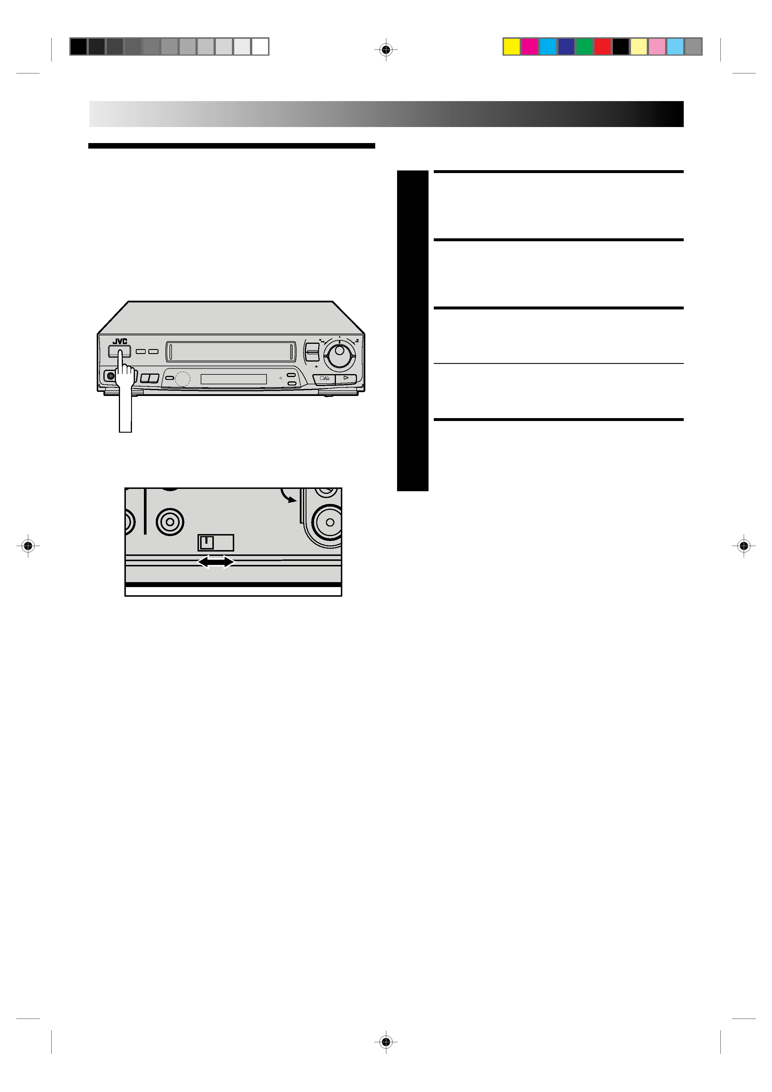
4 EN
INSTALLING YOUR NEW RECORDER (cont.)
Tune The TV
To Your Video
Recorder
TURN ON THE RECORDER
1 PressOPERATE.
SELECT OUTPUT MODE
2 SettheTESTswitchonthebackof therecordertoON.
SET TV CHANNEL
3 SetyourTVtothevideochannel(UHFchannel37).
Two white bars appear on screen vertically.
Tune the TV until the bars are as clear as they can be.
Your TV should be set to the channel designated for
use with a video recorder, or to a spare channel if
there is not a specified video channel on your TV.
RESET OUTPUT MODE
4 ReturntheTESTswitchtoOFF.
NOTES:
If CH37 is occupied by a local station, adjust the RF output
channel adjustment screw to use another channel between
CH33 and CH41 instead.
If some interference noise is continually seen on the screen,
consult your JVC dealer.
The video recorder sends picture and sound signals via the RF
connecting cable to your TV on UHF channel 37.
6
q
Back of VCR
RF OUT
41
TEST
OFF ON
OUT
OPERATE
EN
5
On-Screen
Displays
You can choose whether or not to have various operational
indicators appear on screen, by setting this function ON or OFF.
Messages appear in the language you select.
The superimposed indication on the TV screen tells you what the recorder is doing.
1 Operation mode indicators
2 Channel position number/Aux. indicator (AUX or F-AUX)
3 Cassette loaded mark
4 Tape speed SP/LP/EP
5 Colour System indicator (
pg. 32)
6 Clock display
7 Current day/month/year
8 Tape direction
9 Type of Broadcast (
pg. 17)
10 Tape position indicator (
pg. 13)
11 Counter display (including Counter Memory indicator)
12 Audio mode display
13 B.E.S.T. Picture System indicator
q6
PR. 12
]
SP
23 : 59
PAL
31. 12. 96
B.E.S.T.
ST
H I F I
M 9 : 59 : 59
L
R
0
++
+
+
8
2
6
7
1
Turn on the TV and select the VIDEO channel (or AV mode).
INITIAL SETTINGS
11
4
Use the buttons on the remote control for this procedure.
12
45
3
6
8
0
7
9
5
3
9
10
12
13
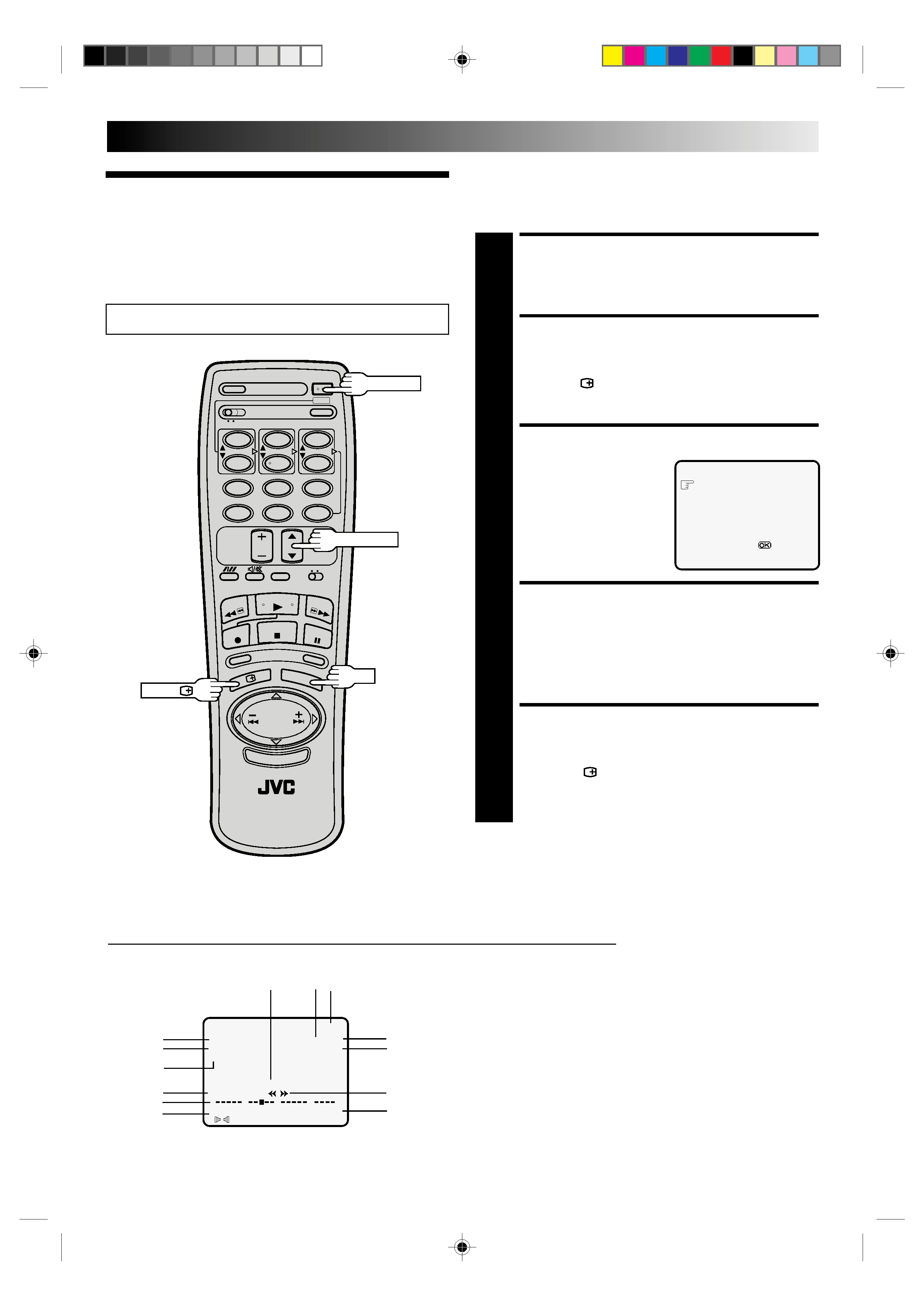
TURN ON THE RECORDER
1 PressOPERATE.
ACCESS MODE SELECT
SCREEN
2 PressOSD( ).TheO.S.D./B.E.S.T.screenappears.
SELECT MODE
3 Thepointershouldalready
be next to "O.S.D.". If not,
press TV PROG.
5/ to
place it there.
ENABLE/DISABLE
ON-SCREEN DISPLAY
4 Thedefaultsettingis"ON",soifyouwanton-screen
displays, leave the setting as is and go to step 5. If you
don't want the displays to appear, press OK to set
"O.S.D." to "OFF".
CLOSE MODE SELECT
SCREEN
5 PressOSD( ).
O.S.D.
: ON
B.E.S.T.
: ON
[TV PROG
5] =
:ON/OFF
[OSD] :EXIT
OPERATE
TV PROG.
5
OK
OSD (
)