SERVICE MANUAL
No.82866
May 2001
HR-J496M/J693M
VIDEOCASSETTE
ESPECIFICAÇÕES (The specifications shown pertain specifically to the model HR-J496M/J693M.)
GERAL
Requisitos de Alimentação : AC 110 V 220 V,
50 Hz/60 Hz
Consumo de energia
Sim
: HR-J693M
16 W
HR-J496M
14 W
Não
: 4,5 W
Temperatura
Em funcionamento : 5
°C a 40°C (41°F a 104°F)
Armazenagem
: 20
°C a 60°C (4°F a 140°F)
Posição de Funcionamento : Apenas na horizental
Dimensões (C x A x P)
: 360 mm x 94 mm x 247 mm
Peso
: 3,1 kg
Formato
: VHS standard
Tempo máximo de gravação
SP
: 210 min. com cassete de
vídeo ST-210
EP
: 630 min. com cassete de
vídeo ST-210
VÍDEO/AUDIO
Sistema de sinal
: PAL-M- sinal de tipo cor e
sinal monocromo EIA, 525
linhas/60 campos, NTSC-
sinal tipo cor e sinal
monocromo EIA, 525
linhas/60 campos (apenas
para leitura)
Sistema de Gravação/
Leitura :
: Cabeça DA-4 (Azimute
duplo), sistema de scan
helicoidal
Racio de sinal-barulho
: 45 dB
Resolução horizental
: 230 linhas
Amplitude de frequência
Audio normal
: 70 Hz a 10,000 Hz
Audio Hi-Fi
(Apenas HR-J693M): 20 Hz a 20,000 Hz
Entrada/Saída
: Ligações RCA
(ENTRADA x 1, SAÍDA x 1)
SINTONIZADOR
Sistema de sintonizador : Frequênciasintonizador
sintetizado
Alcançe dos canais
VHF
: Canais 213
UHF
: Canais 1469
CATV
: 113 Canais
Saída RF
: Canal 3 ou 4 (alterável; pré-
ajustado na fábrica para
canal 3) 75
Não equilibrado
TEMPORIZADOR
Referência de relógio
: Quartz
Capacidade de Programa : 1 ano de temporizador
programável/8 programas
Reserva de tempo de
: Aprox. 6 meses.
Memória
Figura estimadas, baseada no
fornecimento de uma pilha
nova; o funcionamento
concreto pode variar.
ACESSÓRIOS
Acessórios fornecidos
: Cabo RF,
Unidade de controle remoto
de raios infravermelhos,
Pilha de lítio CR2025,
Pilha de tamanho "AA" x 2,
As especificações explicadas referem-se ao modo SP excepto
especificado em contrário.
O design E & O.E e especificações estão sujeitas a alteração
sem aviso prévio.
.
PROG.
CHECK
PROG.
TV operation -- Press and hold
TV button, then press POWER,
TV CH +/--, VOL +/--, TV/VCR
POWER
TV
12
3
45
0AUX
6
78DAILY
9WEEKLY
DISPLAY
TV/VCR
CANCEL
START
REW
FF
PLAY
REC
MENU
OK
STOP
TV CH +
TV CH --
TV
+ VOL
TV
VOL --
PAUSE
STOP
DATE
CH
C.RESET
OSD
ENTER
TIMER
1
2
4
3
NTSC/M-PAL
M-PAL NTSC


TABLE OF CONTENTS
Section
Title
Page
Section
Title
Page
Important Safety Precautions
INSTRUCTIONS
1. DISASSEMBLY
1.1
DISASSEBLY FLOW CHART .................................... 1-1
1.2
HOW TO READ THE DISASSEMBLY AND ASSEMBLY ...... 1-1
1.3
DISASSEMBLY /ASSEMBLY METHOD .................... 1-1
1.4
Service position ......................................................... 1-4
1.4.1 How to set the "Service position" .......................... 1-4
1.5
Mechanism service mode .......................................... 1-4
1.5.1 How to set the "Mechanism service mode" ........... 1-4
1.6
Jig RCU mode ........................................................... 1-4
1.6.1 Setting the Jig RCU mode .................................... 1-4
1.6.2 Setting the User RCU mode ................................. 1-4
1.7
Emergency display function ....................................... 1-5
1.7.1 Displaying the EMG information ........................... 1-5
1.7.2 Clearing the EMG history ...................................... 1-5
1.7.3 EMG content description ...................................... 1-6
1.7.4 EMG detail information <1> .................................. 1-7
1.7.5 EMG detail information <2> .................................. 1-8
2. MECHANISM ADJUSTMENT
2.1
BEFORE STARTING REPAIR AND ADJUSTMENT . 2-1
2.1.1 Precautions ........................................................... 2-1
2.1.2 Checking for proper mechanical operations ......... 2-1
2.1.3 Manually removing the cassette tape ................... 2-1
2.1.4 Jigs and tools required for adjustment .................. 2-2
2.1.5 Maintenance and inspection ................................. 2-3
2.2
REPLACEMENT OF MAJOR PARTS ....................... 2-6
2.2.1 Before starting disassembling
(Phase matching between mechanical parts) ....... 2-6
2.2.2 How to set the "Mechanism assembling mode" .... 2-6
2.2.3 Cassette holder assembly .................................... 2-6
2.2.4 Pinch roller arm assembly .................................... 2-8
2.2.5 Guide arm assembly and press lever assembly ..... 2-8
2.2.6 Audio control head ................................................ 2-8
2.2.7 Loading motor ....................................................... 2-8
2.2.8 Capstan motor ...................................................... 2-9
2.2.9 Pole base assembly (supply or take-up side) ....... 2-9
2.2.10 Rotary encoder ................................................... 2-10
2.2.11 Clutch unit ........................................................... 2-10
2.2.12 Change lever assembly,direct gear,clutch gear
and coupling gear ............................................... 2-10
2.2.13 Link lever ............................................................ 2-11
2.2.14 Cassette gear,control cam and worm gear ......... 2-11
2.2.15 Control plate ....................................................... 2-11
2.2.16 Loading arm gear (supply or take-up side)
and loading arm gear shaft ................................. 2-12
2.2.17 Take-up lever,take-up head and control plate guide .... 2-13
2.2.18 Capstan brake assembly .................................... 2-13
2.2.19 Sub brake assembly (take-up side) .................... 2-13
2.2.20 Main brake assembly (take-up side),
reel disk (take-up side) and
main brake assembly (supply side) .................... 2-13
2.2.21 Tension brake assembly, reel disk (supply side)
and tension arm assembly .................................. 2-14
2.2.22 Idler lever, idler arm assembly ............................ 2-14
2.2.23 Stator assembly .................................................. 2-14
2.2.24 Rotor assembly ................................................... 2-14
2.2.25 Upper drum assembly ......................................... 2-15
2.3
COMPATIBILLTIY ADJUSTMENT ........................... 2-16
2.3.1 FM waveform linearity ......................................... 2-16
2.3.2 Height and tilt of the A/C head ............................ 2-17
2.3.3 A/C head phase (X-value) .................................. 2-17
2.3.4 Standard tracking preset ..................................... 2-18
2.3.5 Tension pole position .......................................... 2-18
3. ELECTRICAL ADJUSTMENT
3.1
PRECAUTION ........................................................... 3-1
3.1.1 Required test equipments ..................................... 3-1
3.1.2 Required adjustment tools .................................... 3-1
3.1.3 Color (colour) bar signal,color (colour) bar pattern ...... 3-1
3.1.4 Switch settings and standard precautions ............ 3-1
3.2
SERVO CIRCUIT ....................................................... 3-2
3.2.1 Switching point ...................................................... 3-2
3.2.2 Slow tracking preset ............................................. 3-2
3.3
VIDEO CIRCUIT ....................................................... 3-2
3.3.1 Auto picture initial settings .................................... 3-2
3.4
SYSCON CIRCUIT ................................................... 3-2
3.4.1 Timer clock ............................................................ 3-2
4. CHARTS AND DIAGRAMS
4.1
BOARD INTERCONNECTIONS ............................... 4-3
4.2
MAIN (VIDEO/AUDIO) SCHEMATIC DIAGRAM ....... 4-5
4.3
MAIN (SYSCON) AND
LT BATTERY SCHEMATIC DIAGRAMS ............. 4-7
4.4
MAIN (SW.REG) SCHEMATIC DIAGRAM ................ 4-9
4.5
MAIN (TUNER) SCHEMATIC DIAGRAM ................ 4-11
4.6
MAIN (FMA/DEMOD)
SCHEMATIC DIAGRAM [HR-J693M/J696EN] ........ 4-13
4.7
MAIN (FRONT) SCHEMATIC DIAGRAM ................ 4-15
4.8
MAIN (TERMINAL) SCHEMATIC DIAGRAMS ........ 4-17
4.9
MAIN CIRCUIT BOARD .......................................... 4-19
4.10 ADV. JOG SCHEMATIC DIAGRAM [HR-J696EN] ...... 4-21
4.11 REMOTE CONTROLLER SCHEMATIC DIAGRAM ... 4-22
4.12 FDP GRID ASSIGNMET AND
ANODE CONNECTION .................................. 4-23
4.13 WAVEFORMS ......................................................... 4-24
4.14 VOLTAGE CHARTS ................................................ 4-25
4.15 CPU PIN FUNCTION .............................................. 4-26
4.16 SYSTEM CONTROL BLOCK DIAGRAM ................ 4-27
4.17 VIDEO BLOCK DIAGRAM ...................................... 4-29
4.18 AUDIO BLOCK DIAGRAM ...................................... 4-31
5. PARTS LIST
5.1
PACKING AND ACCESSORY ASSEMBLY <M1> ..... 5-1
5.2
FINAL ASSEMBLY <M2> ........................................... 5-2
5.3
MECHANISM ASSEMBLY <M4> ............................... 5-4
5.4
ELECTRICAL PARTS LIST ....................................... 5-6
MAIN BOARD ASSEMBLY <03> ............................... 5-6
AUDIO CONTROL HEAD BOARD ASSEMBLY<12> .. 5-11
LOADING MOTOR BOARD ASSEMBLY <55> ....... 5-11
LT BATTERY BOARD ASSEMBLY <93> ................. 5-11
The following table indicate main different points between models HR-J496M and HR-J693M.
MODEL
HR-J496M
HR-J693M
ITEM
FMA HEAD
NOT USED
USED
F-1in [COLOR]
V,A [SLV/BLACK]
V,LR [SLV/BLACK]
AV out [COLOR]
Vx1,Ax1[SLV/Y,W]
Vx1,LRx1[SLV/Y,WR]
HI-FI
NOT USED
USED
STEREO DECODER
NOT USED
MTS
Important Safety Precautions
Prior to shipment from the factory, JVC products are strictly inspected to conform with the recognized product safety and electrical codes
of the countries in which they are to be sold. However, in order to maintain such compliance, it is equally important to implement the
following precautions when a set is being serviced.
Fig.1
1. Locations requiring special caution are denoted by labels and
inscriptions on the cabinet, chassis and certain parts of the
product. When performing service, be sure to read and com-
ply with these and other cautionary notices appearing in the
operation and service manuals.
2. Parts identified by the
symbol and shaded (
) parts are
critical for safety.
Replace only with specified part numbers.
Note: Parts in this category also include those specified to com-
ply with X-ray emission standards for products using
cathode ray tubes and those specified for compliance
with various regulations regarding spurious radiation
emission.
3. Fuse replacement caution notice.
Caution for continued protection against fire hazard.
Replace only with same type and rated fuse(s) as specified.
4. Use specified internal wiring. Note especially:
1) Wires covered with PVC tubing
2) Double insulated wires
3) High voltage leads
5. Use specified insulating materials for hazardous live parts.
Note especially:
1) Insulation Tape
3) Spacers
5) Barrier
2) PVC tubing
4) Insulation sheets for transistors
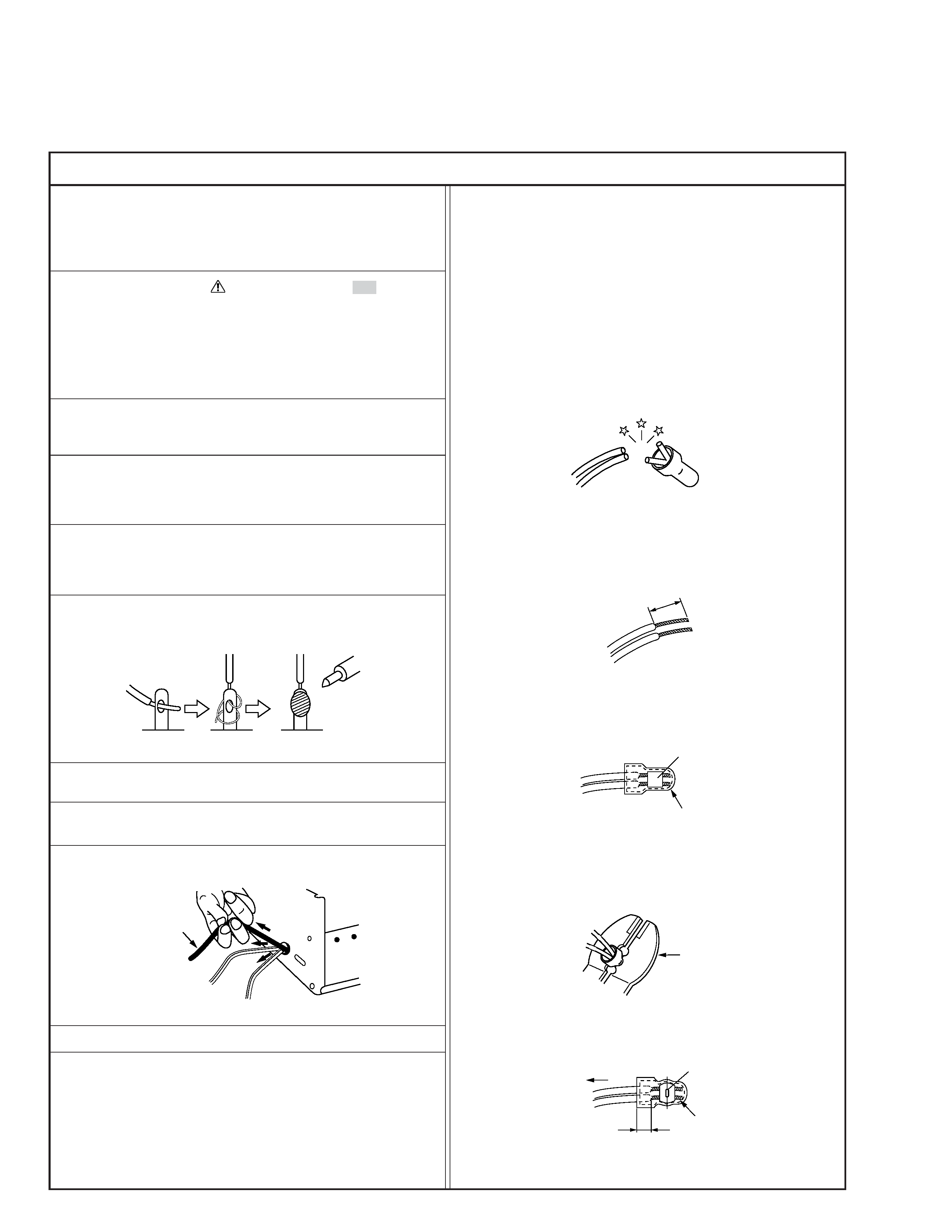
6. When replacing AC primary side components (transformers,
power cords, noise blocking capacitors, etc.) wrap ends of
wires securely about the terminals before soldering.
Power cord
Fig.2
10. Also check areas surrounding repaired locations.
11. Products using cathode ray tubes (CRTs)
In regard to such products, the cathode ray tubes themselves,
the high voltage circuits, and related circuits are specified for
compliance with recognized codes pertaining to X-ray emission.
Consequently, when servicing these products, replace the cath-
ode ray tubes and other parts with only the specified parts.
Under no circumstances attempt to modify these circuits.
Unauthorized modification can increase the high voltage value
and cause X-ray emission from the cathode ray tube.
12. Crimp type wire connector
In such cases as when replacing the power transformer in sets
where the connections between the power cord and power
transformer primary lead wires are performed using crimp type
connectors, if replacing the connectors is unavoidable, in or-
der to prevent safety hazards, perform carefully and precisely
according to the following steps.
1) Connector part number : E03830-001
2) Required tool : Connector crimping tool of the proper type
which will not damage insulated parts.
3) Replacement procedure
(1) Remove the old connector by cutting the wires at a point
close to the connector.
Important : Do not reuse a connector (discard it).
Fig.7
cut close to connector
Fig.3
(2) Strip about 15 mm of the insulation from the ends of
the wires. If the wires are stranded, twist the strands to
avoid frayed conductors.
15 mm
Fig.4
(3) Align the lengths of the wires to be connected. Insert
the wires fully into the connector.
Connector
Metal sleeve
Fig.5
(4) As shown in Fig.6, use the crimping tool to crimp the
metal sleeve at the center position. Be sure to crimp fully
to the complete closure of the tool.
1
Precautions during Servicing
7. Observe that wires do not contact heat producing parts
(heatsinks, oxide metal film resistors, fusible resistors, etc.)
8. Check that replaced wires do not contact sharp edged or
pointed parts.
9. When a power cord has been replaced, check that 10-15 kg of
force in any direction will not loosen it.
1.25
2.0
5.5
Crimping tool
Fig.6
(5) Check the four points noted in Fig.7.
Not easily pulled free
Crimped at approx. center
of metal sleeve
Conductors extended
Wire insulation recessed
more than 4 mm
S40888-01
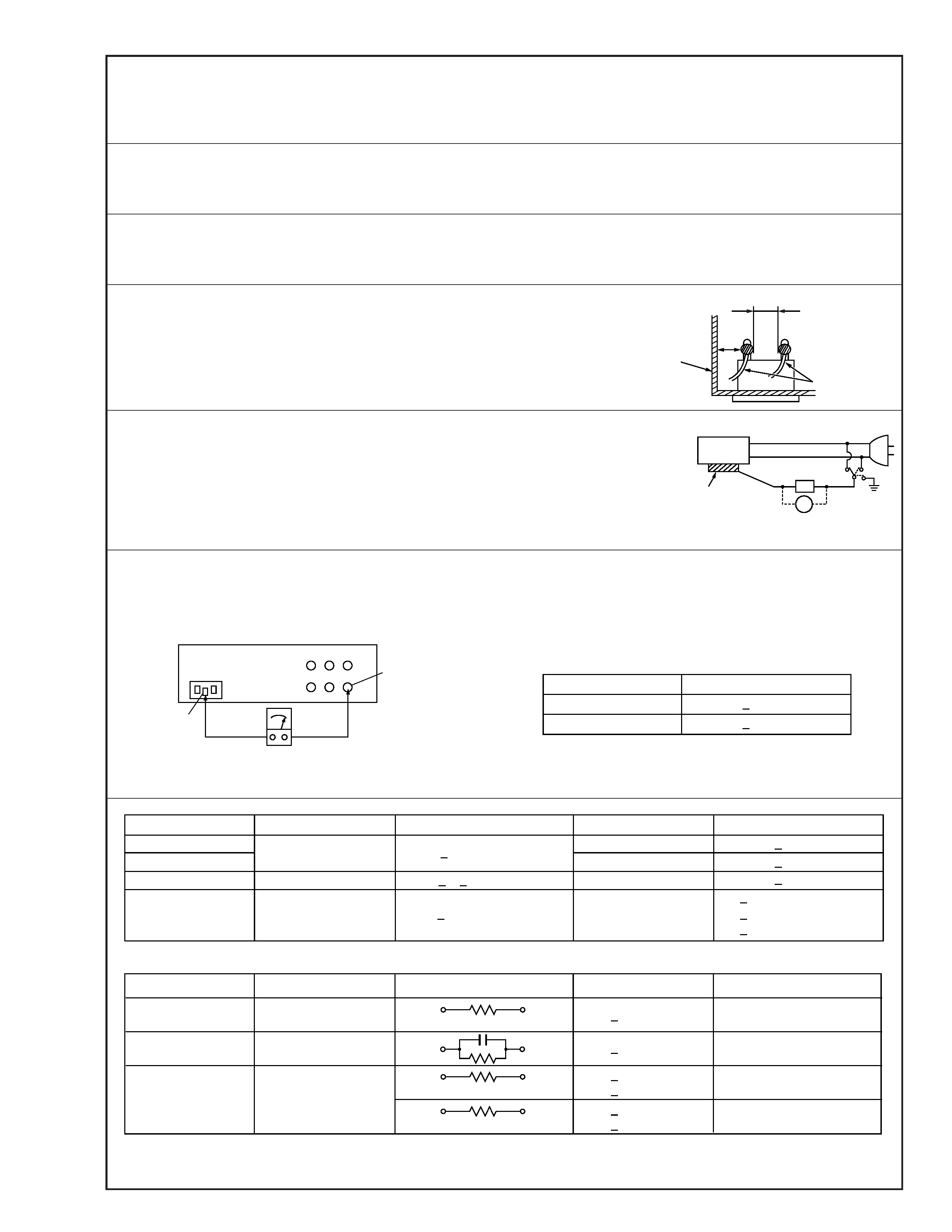
Safety Check after Servicing
Examine the area surrounding the repaired location for damage or deterioration. Observe that screws, parts and wires have been
returned to original positions, Afterwards, perform the following tests and confirm the specified values in order to verify compli-
ance with safety standards.
1. Insulation resistance test
Confirm the specified insulation resistance or greater between power cord plug prongs and
externally exposed parts of the set (RF terminals, antenna terminals, video and audio input
and output terminals, microphone jacks, earphone jacks, etc.). See table 1 below.
2. Dielectric strength test
Confirm specified dielectric strength or greater between power cord plug prongs and exposed
accessible parts of the set (RF terminals, antenna terminals, video and audio input and output
terminals, microphone jacks, earphone jacks, etc.). See table 1 below.
3. Clearance distance
When replacing primary circuit components, confirm specified clearance distance (d), (d') be-
tween soldered terminals, and between terminals and surrounding metallic parts. See table 1
below.
4. Leakage current test
Confirm specified or lower leakage current between earth ground/power cord plug prongs
and externally exposed accessible parts (RF terminals, antenna terminals, video and audio
input and output terminals, microphone jacks, earphone jacks, etc.).
Measuring Method : (Power ON)
Insert load Z between earth ground/power cord plug prongs and externally exposed accessi-
ble parts. Use an AC voltmeter to measure across both terminals of load Z. See figure 9 and
following table 2.
5. Grounding (Class 1 model only)
Confirm specified or lower grounding impedance between earth pin in AC inlet and externally exposed accessible parts (Video in,
Video out, Audio in, Audio out or Fixing screw etc.).
Measuring Method:
Connect milli ohm meter between earth pin in AC inlet and exposed accessible parts. See figure 10 and grounding specifications.
d'
d
Chassis
Power cord,
primary wire
Region
USA & Canada
Europe & Australia
Grounding Impedance (Z)
Z
0.1 ohm
Z
0.5 ohm
AC inlet
Earth pin
Exposed accessible part
Milli ohm meter
Grounding Specifications
Fig. 10
ab
c
V
Externally
exposed
accessible part
Z
Fig. 9
Fig. 8
Clearance Distance (d), (d')
d, d'
3 mm
d, d'
4 mm
d, d'
3.2 mm
1 M
R 12 M/500 V DC
Dielectric Strength
AC 1 kV 1 minute
AC 1.5 kV 1 miute
AC 1 kV 1 minute
AC Line Voltage
100 V
100 to 240 V
110 to 130 V
110 to 130 V
200 to 240 V
Japan
USA & Canada
Europe & Australia
R
10 M
/500 V DC
Region
Insulation Resistance (R)
R
1 M
/500 V DC
AC 3 kV 1 minute
(Class
2)
AC 1.5 kV 1 minute
(Class
1)
d
4 mm
d'
8 mm (Power cord)
d'
6 mm (Primary wire)
Table 1 Specifications for each region
a, b, c
Leakage Current (i)
AC Line Voltage
100 V
110 to 130 V
110 to 130 V
220 to 240 V
Japan
USA & Canada
i
1 mA rms
Exposed accessible parts
Exposed accessible parts
Antenna earth terminals
Other terminals
i
0.5 mA rms
i
0.7 mA peak
i
2 mA dc
i
0.7 mA peak
i
2 mA dc
Europe & Australia
Region
Load Z
1 k
2 k
1.5 k
0.15
µF
50 k
Table 2 Leakage current specifications for each region
Note: These tables are unofficial and for reference only. Be sure to confirm the precise values for your particular country and locality.
2
S40888-01