HR-J430KR
VIDEO CASSETTE RECORDER
INSTRUCTIONS
PU30425-1930
For Customer Use:
Enter below the Serial No. which is
located on the rear of cabinet. Retain
this information for future reference.
Model No.
HR-J430KR
Serial No.
C.M
EMOR
Y
SKIP SEAR
CH
POWER
ENTER
PLAY
STOP
OSD
DAILY (M-F)
AUX
C.RESET
CH SKIP
CANCEL
TV
VOL.
CH
DISPLAY TV/VIDEO
TV
VCR
TIMER
WEEKLY
A
12
45
3
6
8
0
7
9
B
MULTI BRAND
REMOTE CONTROL UNIT
REW
REC
FF
PAUSE
ADD
MEN
U
OK
ILLUMI GUIDE
PUSH JOG
FF
REW
C.MEMORY
START/
MENU
VIDEO
AUDIO
CH 5
POWER
OK
6
q
HM
S
REC
PAUSE
PLAY
I T R
TIMER
VIDEO
M
SP
EP
AM
PM
2
Dear Customer,
Thank you for purchasing the JVC VHS video cassette recorder. Before use, please read the safety information and precautions
contained in the following pages to ensure safe use of your new VCR.
CAUTIONS
WARNING:
TO PREVENT FIRE OR SHOCK
HAZARD, DO NOT EXPOSE THIS
UNIT TO RAIN OR MOISTURE.
CAUTION:
This video cassette recorder should be used with AC
110V220V`, 60Hz only.
To prevent electric shocks and fire hazards, DO NOT use
any other power source.
CAUTION:
TO PREVENT ELECTRIC SHOCK, MATCH WIDE
BLADE OF PLUG TO WIDE SLOT, FULLY INSERT.
ATTENTION:
POUR ÉVITER LES CHOCS ÉLECTRIQUES, INTRODUIRE
LA LAME LA PLUS LARGE DE LA FICHE DANS LA BORNE
CORRESPONDANTE DE LA PRISE ET POUSSER
JUSQU'AU FOND.
CAUTION
RISK OF ELECTRIC SHOCK
DO NOT OPEN
CAUTION:
TO REDUCE THE RISK OF ELECTRIC SHOCK.
DO NOT REMOVE COVER (OR BACK).
NO USER-SERVICEABLE PARTS INSIDE.
REFER SERVICING TO QUALIFIED SERVICE PERSONNEL.
The lightning flash with arrowhead symbol, within an equilateral
triangle, is intended to alert the user to the presence of
uninsulated "dangerous voltage" within the product's enclosure
that may be of sufficient magnitude to constitute a risk of electric
shock to persons.
The exclamation point within an equilateral triangle is intended to
alert the user to the presence of important operating and
maintenance
(servicing)
instructions
in
the
literature
accompanying the appliance.
Failure to heed the following precautions may result in
damage to the VCR, remote control or video cassette.
1. DO NOT place the VCR . . .
... in an environment prone to extreme temperatures or
humidity.
... in direct sunlight.
... in a dusty environment.
... in an environment where strong magnetic fields are
generated.
... on a surface that is unstable or subject to vibration.
2. DO NOT block the VCR's ventilation openings.
3. DO NOT place heavy objects on the VCR or remote control.
4. DO NOT place anything which might spill on top of the
VCR or remote control.
5. AVOID violent shocks to the VCR during transport.
**MOISTURE CONDENSATION
Moisture in the air will condense on the VCR when you move it
from a cold place to a warm place, or under extremely humid
conditions--just as water droplets form on the surface of a glass
filled with cold liquid. Moisture condensation on the head drum
will cause damage to the tape. In conditions where condensa-
tion may occur, keep the VCR's power turned on for a few
hours to let the moisture dry.
**ABOUT HEAD CLEANING
Accumulation of dirt and other particles on the video heads may
cause the playback picture to become blurred or interrupted. Be
sure to contact your nearest JVC dealer if such troubles occur.
Note to CATV system installer:
This reminder is provided to call the CATV system
installer's attention to Article 820-40 of the NEC that
provides guidelines for proper grounding and, in particular,
specifies that the cable ground shall be connected to the
grounding system of the building, as close to the point of
cable entry as practical.
CAUTION:
Changes or modifications not approved by JVC could void
user's authority to operate the equipment.
Cassettes marked "VHS" (or "S-VHS") can be used with this
video cassette recorder. However, only "VHS" recordings can
be played back in this model.
HQ VHS is compatible with existing VHS equipment.
G-Code is a trademark applied for by Gemstar Development
Corporation.
G-Code system is manufactured under licence from Gemstar
Development Corporation.
HOW TO USE THIS INSTRUCTION
MANUAL
All major sections and subsections are listed in the Table
Of Contents on page 3. Use this when searching for
information on a specific procedure or feature.
The Index on pages 42 43 lists frequently-used terms,
and the number of the first page on which they are used
or explained in the manual. This section also illustrates
the controls and connections on the front and rear panel,
the front display panel and the remote control.
The
mark signals a reference to another page for
instructions or related information.
Operation buttons necessary for the various procedures
are clearly indicated through the use of illustrations at
the beginning of each major section.
BEFORE YOU INSTALL YOUR NEW
VCR . . .
. . . please read thoroughly the cautions on this page.
3
CONTENTS
TIMER RECORDING
25
Instant Timer Recording (ITR) ............... 25
G-Code Timer Programming ................ 26
On-Screen Timer Programming ........... 28
Check And Cancel Programs .......................... 30
Auto SP/EP Timer ............................................ 31
Auto Timer ......................................................32
SPECIAL FEATURES
33
TV Multi-Brand Remote Control ..................... 33
EDITING
34
Edit From A Camcorder ....................... 34
Edit To Or From Another VCR ............... 35
Control Two JVC VCRs ................................... 35
Random Assemble Editing ................... 36
TROUBLESHOOTING
38
Power ................................................. 38
Tape Transport ..................................... 38
Playback ............................................. 38
Recording ............................................ 38
Timer Recording ................................... 39
Other Problems.................................... 39
QUESTIONS AND ANSWERS 40
Playback ............................................. 40
Recording ............................................ 40
Timer Recording ................................... 40
SPECIFICATIONS
41
INDEX
42
Front View ........................................... 42
Rear View ........................................... 42
Front Display Panel .............................. 43
Remote Control ....................................43
INSTALLING YOUR NEW VCR
4
Basic Connections ..................................4
INITIAL SETTINGS
5
Clock ..................................................... 5
Tuner ..................................................... 6
Set Receivable Channels .................................. 6
Add Or Delete A Channel ................................ 8
G-Code Setup .........................................9
SIMPLE PLAYBACK AND
RECORDING
12
Simple Playback .................................. 12
Simple Recording ................................. 13
PLAYBACK AND RECORDING
FEATURES
14
Playback ............................................. 14
Still Picture/Frame-By-Frame Playback ........... 14
Slow Motion/Reverse Slow Motion ................. 14
Variable-Speed Search/Reverse Play ............... 15
High-Speed Search ......................................... 15
Manual Tracking............................................. 16
Superimpose ................................................... 17
Skip Search ..................................................... 18
Repeat Playback ............................................. 18
Index Search ................................................... 18
Instant ReView ................................................ 19
Counter Reset ..................................................19
Counter Memory ............................................ 19
Tape Position Indicator ................................... 20
Next-Function Memory .................................. 20
B.E.S.T. Picture System......................... 21
Preparation ..................................................... 21
Recording ....................................................... 22
Playback ......................................................... 23
Recording ............................................ 24
Record One Program While
Watching Another .......................................... 24
Display Elapsed Recording Time ..................... 24
4
INSTALLING YOUR NEW VCR
CHECK CONTENTS
1 Makesurethepackagecontainsalloftheaccessories
listed in "SPECIFICATIONS" (
pg. 41).
SITUATE VCR
2 PlacetheVCRonastable,horizontalsurface.
CONNECT VCR TO TV
3 Theconnectionmethodyouusedependsonthetypeof
TV you have.
RF Connection
To Connect To A TV With NO AV Input Terminals . . .
a Disconnect the TV antenna from the TV.
b Connect the TV antenna cable to the ANT IN jack
on the rear of the VCR.
c Connect the supplied RF cable between the RF
OUT jack on the rear of the VCR and the TV's
antenna terminal.
AV Connection
To Connect To A TV With AV Input Terminals . . .
a Connect the antenna, VCR and TV as shown in
the illustration.
b Connect an Audio/Video Cable between the AUDIO
OUT and VIDEO OUT jacks on the rear of the VCR
and the AV IN jacks on the TV.
CONNECT VCR TO
POWER SOURCE
4 ConnectthepowerplugtoanACoutlet.
FINAL PREPARATION FOR
USE
5 SelecttheVCRchannel(3or4)bysettingtheswitch
on the rear of the VCR as shown in the illustration.
Turn on the power to the TV. You are now able to perform
simple playback (
pg. 12) and recording (
pg. 13).
NOTES:
The VCR channel is the channel on the TV which will display
the audio and video signals from the VCR. The VCR's CH3-
CH4 switch sets the VCR channel to CH3 or CH4.
The CH3CH4 switch is preset to the CH3 position.
Set to CH4 if CH3 is used for broadcasting in your area.
If your TV has no AV input terminals, set the channel on the
TV to correspond to the CH3CH4 switch on the back of the
VCR.
Even if your TV has AV input terminals, you must connect it
to the VCR using an RF cable in order to record one show
while watching another (
pg. 24).
For full identification of the VCR's rear panel, refer to the
Index (REAR VIEW
pg. 42).
AC Power
Cord
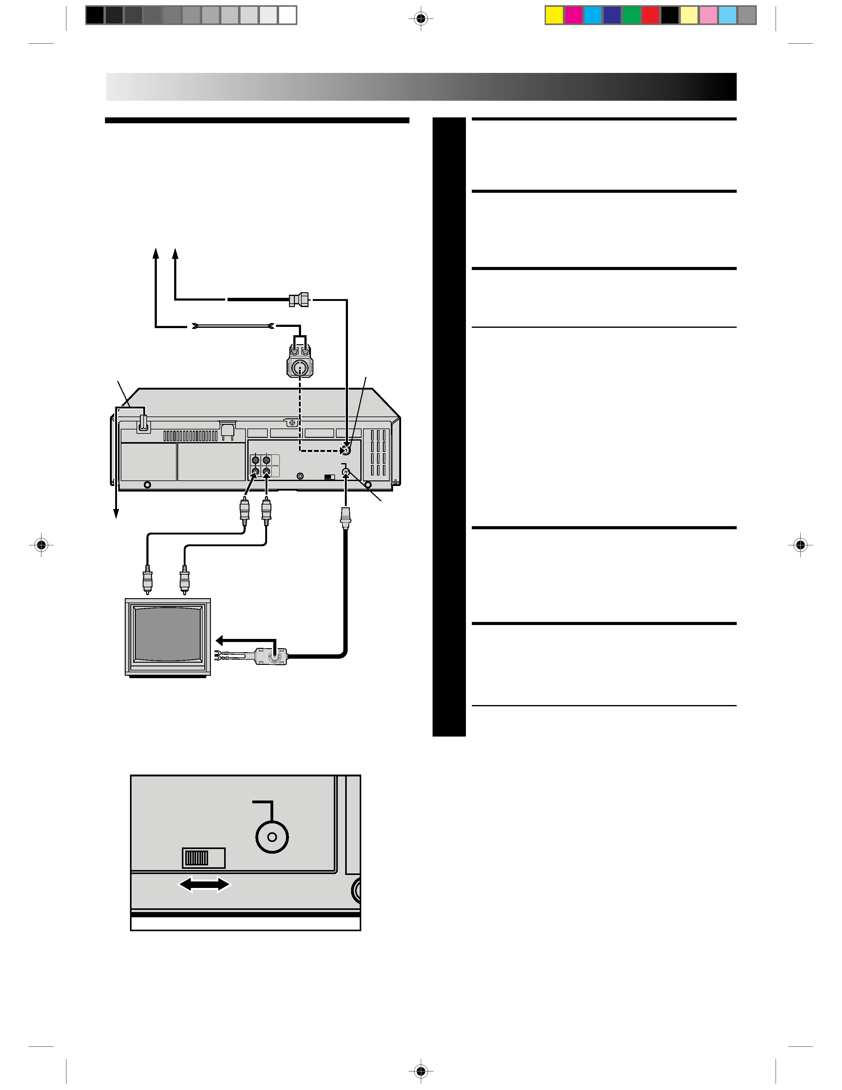
Basic
Connections
Antenna or Cable
Coaxial Cable
Flat Feeder
Matching Transformer
Back of VCR
AC
Outlet
ANTENNA-
IN (Antenna
or Cable
input)
RF
OUT
Video Cable
(not supplied)
RF Cable
(supplied)
Audio Cable
(not supplied)
75 ohm terminal
300 ohm terminal
TV
CH3
CH4
RF OUT
Back of VCR
5
12
45
3
6
8
0
7
9
5
6
q
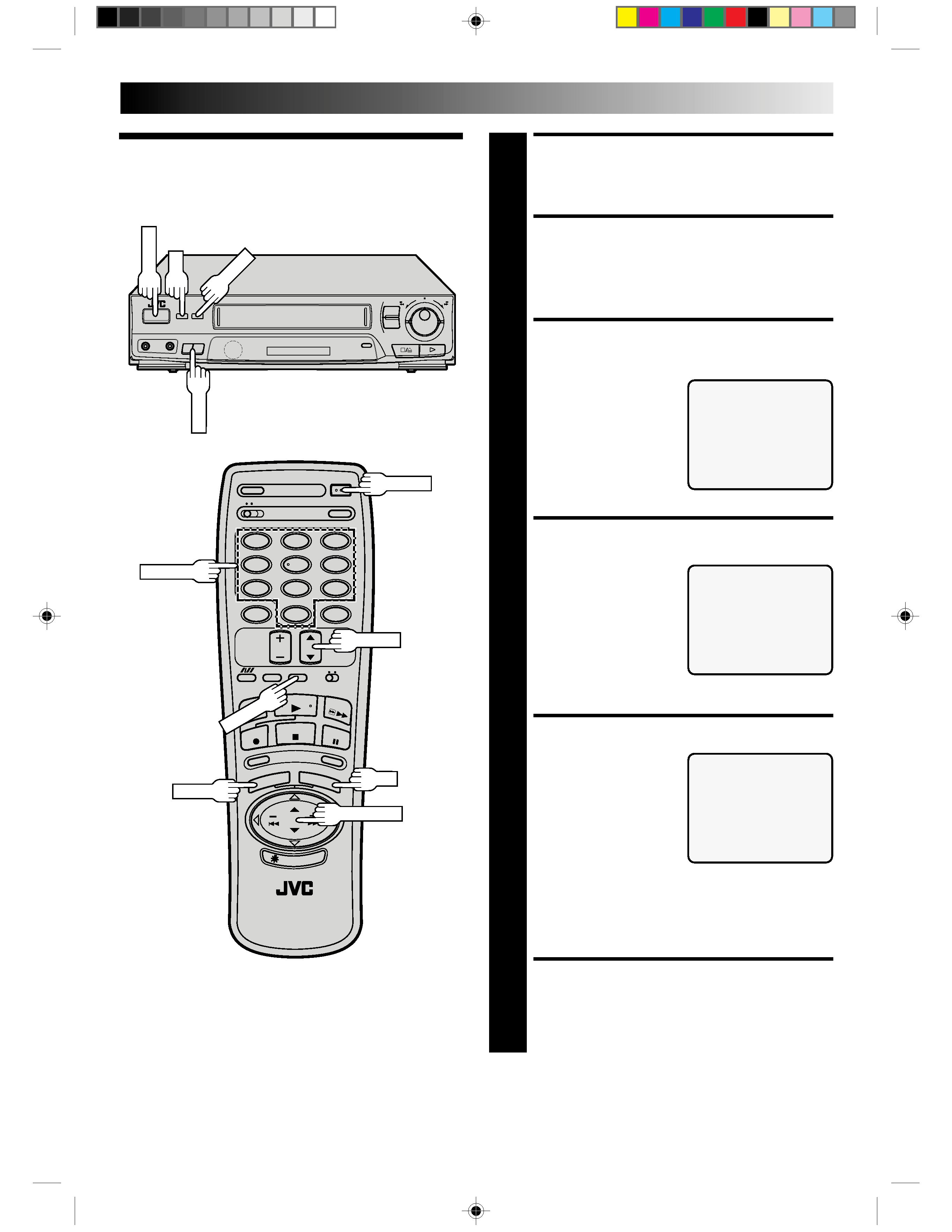
Clock
TURN ON THE VCR
1 PressPOWER.Ifwatchingchannel3or4,press
TV/VIDEO to select the VIDEO mode. VIDEO is
displayed on the front display panel.
ACCESS ON-SCREEN
MENU
2 PressMENUtobringuptheMainMenuscreen.
ACCESS INITIAL SET
SCREEN
3 AttheMainMenuscreen,
place the arrow next to
"INITIAL SET" by pressing
CH
5 or PUSH JOG5,
then press OK.
ACCESS CLOCK SET
SCREEN
4 Placethearrowatthe
Initial Set screen next to
"CLOCK SET" by pressing
CH
5 or PUSH JOG5,
then press OK.
SET DATE AND TIME
5 Presstheappropriate
NUMBER keys to set the
date and time (if only 1
digit, press "0" first). Press
CHvw or PUSH JOG
5
to set AM/PM, then press
OK . The next setting that
can be set begins flashing.
When you're finished with
this set-up procedure, press MENU to start the clock.
NOTE:
CHvw or PUSH JOG
5can be used to perform all
operations. (In this case, press OK after each setting.)
MAKE CORRECTIONS
6 Tochangeanyofthesettings,pressOKorPUSHJOG
TM£
until the item you want to change blinks,
then set as in step 5.
INITIAL SETTINGS
MAIN MENU
PROGRAM SET
FUNCTION SET
TUNER SET
=INITIAL SET
B.E.S.T.PICTURE SYSTEM
R.A. EDIT
PRESS (
5,) THEN (OK)
PRESS (MENU) TO END
INITIAL SET
=CLOCK SET
G-CODE SET-UP
PRESS (
5,), THEN (OK)
PRESS (MENU) TO END
CH
5
POWER
NUMBER
MENU
OK
PUSH JOG
CH
5
TV/VIDEO
POWER
MENU
OK
CLOCK SET
DATE
1/ 1/96 MON
TIME
: AM
PRESS NUMBER KEY(0-9)
OR (
5,), THEN (OK)
PRESS (MENU) TO END