SERVICE MANUAL
COPYRIGHT © 2004 Victor Company of Japan, Limited
No.YD007
2004/7
VIDEO CASSETTE RECORDER
YD007
2004
7
HR-J4020UA, HR-J4020UB,
HR-J7020UA, HR-J7020UM
For disassembling and assembling of MECHANISM ASSEMBLY, refer to the SERVICE MANUAL No.86700(MECHANISM ASSEMBLY).
TABLE OF CONTENTS
1
PRECAUTION. . . . . . . . . . . . . . . . . . . . . . . . . . . . . . . . . . . . . . . . . . . . . . . . . . . . . . . . . . . . . . . . . . . . . . . . . 1-3
2
SPECIFIC SERVICE INSTRUCTIONS . . . . . . . . . . . . . . . . . . . . . . . . . . . . . . . . . . . . . . . . . . . . . . . . . . . . . . 1-5
3
DISASSEMBLY . . . . . . . . . . . . . . . . . . . . . . . . . . . . . . . . . . . . . . . . . . . . . . . . . . . . . . . . . . . . . . . . . . . . . . . 1-8
4
ADJUSTMENT . . . . . . . . . . . . . . . . . . . . . . . . . . . . . . . . . . . . . . . . . . . . . . . . . . . . . . . . . . . . . . . . . . . . . . . 1-10
5
TROUBLESHOOTING . . . . . . . . . . . . . . . . . . . . . . . . . . . . . . . . . . . . . . . . . . . . . . . . . . . . . . . . . . . . . . . . . 1-14
HR-J4020UA, HR-J4020UB,
HR-J7020UA, HR-J7020UM [V17C1, V17D0]
(UA model)
(UB, UM model)
(UA model)
(UB, UM model)
(HR-J7020UA, HR-J7020UM)
1-2 (No.YD007)
SPECIFICATION
Specifications shown are for SP mode unless otherwise specified.
E.& O.E. Design and specifications subject to change without notice.
HR-J4020UA
HR-J7020UA
HR-J4020UB
HR-J7020UM
GENERAL
Power requirement
AC 110 V - 220 V, 50 Hz/60 Hz
Power consumption
Power on
14 W
Power off
3.1 W
Temperature
Operating
5
°C to 40°C
Storage
-20
°C to 60°C
Operating position
Horizontal only
Dimensions (W
× H × D)
360 mm
× 98 mm × 255 mm
Weight
2.9 kg
Format
VHS PAL-N/NTSC standard
VHS NTSC standard
Maximum recording time
(SP)
240 min. with E-240 video cassette(PAL-N)
160 min. with T-160 video cassette(NTSC)
210 min. with T-210 video cassette
(LP)
480 min. with E-240 video cassette(PAL-N)
-
(EP)
480 min. with T-160 video cassette(NTSC)
630 min. with T-210 video cassette
VIDEO/AUDIO
Signal system
PAL-N-type color signal and EIA monochrome
signal, 625 lines/50 fields
NTSC-type color signal and EIA monochrome
signal, 525 lines/60 fields
PAL-M-type color signal
and EIA monochrome
signal, 525 lines/60
fields
NTSC-type color signal
and EIA monochrome
signal, 525 lines/60
fields
NTSC-type color signal
and EIA monochrome
signal, 525 lines/60
fields
Recording/Playback system
DA4 (Double Azimuth) head helical scan system
Signal-to-noise ratio
45 dB
Horizontal resolution
240 lines(PAL-N)/230 lines(NTSC)
240 lines
230 lines
Frequency range
Normal audio
70 Hz to 10,000 Hz
Hi-Fi audio
-
20 Hz to 20,000 Hz
-
20 Hz to 20,000 Hz
Input/Output
RCA connectors (IN
× 2, OUT × 1)
RCA connectors
(IN
× 1, OUT × 1)
TUNER
Tuning system
Frequency synthesized tuner
Channel coverage
VHF : Channels 2-13, UHF : Channels 14-69, CATV : 113 Channels
RF output
Channel 3 or 4 (switchable; preset to Channel 3 when shipped) 75
, unbalanced
TIMER
Clock reference
Quartz
Program capacity
1-year programmable timer/8 programs
ACCESSORIES
Provided accessories
RF cable, Infrared remote control unit, Lithium battery - CR2032 -
RF cable, Infrared re-
mote control unit, Lithi-
um battery - CR2032 -,
Conversion plug
(No.YD007)1-3
SECTION 1
PRECAUTION
1.1
SAFTY PRECAUTIONS
Prior to shipment from the factory, JVC products are strictly in-
spected to conform with the recognized product safety and elec-
trical codes of the countries in which they are to be
sold.However,in order to maintain such compliance, it is equally
important to implement the following precautions when a set is
being serviced.
1.1.1 Precautions during Servicing
(1) Locations requiring special caution are denoted by labels
and inscriptions on the cabinet, chassis and certain parts of
the product.When performing service, be sure to read and
comply with these and other cautionary notices appearing
in the operation and service manuals.
(2) Parts identified by the
symbol and shaded (
) parts
are critical for safety.
Replace only with specified part numbers.
NOTE :
Parts in this category also include those specified to
comply with X-ray emission standards for products
using cathode ray tubes and those specified for
compliance with various regulations regarding spu-
rious radiation emission.
(3) Fuse replacement caution notice.
Caution for continued protection against fire hazard.
Replace only with same type and rated fuse(s) as speci-
fied.
(4) Use specified internal wiring. Note especially:
· Wires covered with PVC tubing
· Double insulated wires
· High voltage leads
(5) Use specified insulating materials for hazardous live parts.
Note especially:
· Insulation Tape
· PVC tubing
·Spacers
· Insulation sheets for transistors
·Barrier
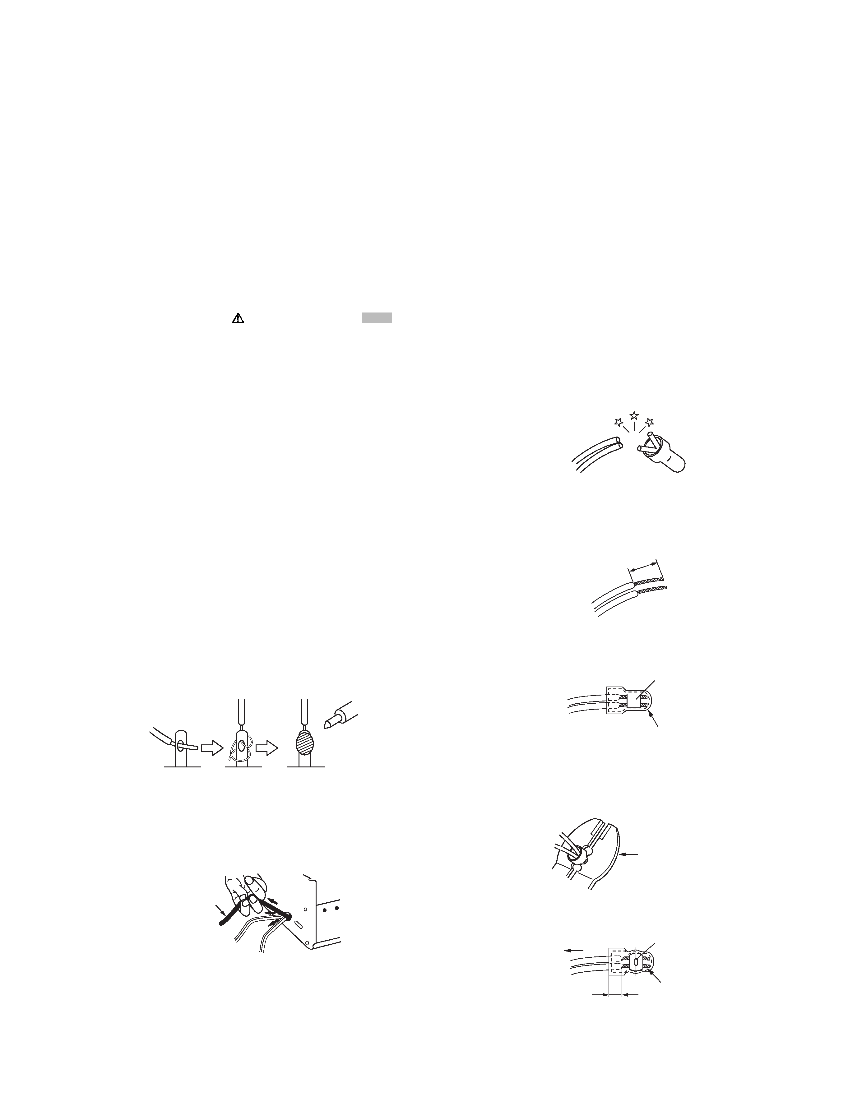
(6) When replacing AC primary side components (transformers,
power cords, noise blocking capacitors, etc.) wrap ends of
wires securely about the terminals before soldering.
Fig.1-1-1
(7) Observe that wires do not contact heat producing parts
(heatsinks, oxide metal film resistors, fusible resistors, etc.)
(8) Check that replaced wires do not contact sharp edged or
pointed parts.
(9) When a power cord has been replaced, check that 10-15
kg of force in any direction will not loosen it.
Fig.1-1-2
(10) Also check areas surrounding repaired locations.
(11) Products using cathode ray tubes (CRTs)In regard to such
products, the cathode ray tubes themselves, the high volt-
age circuits, and related circuits are specified for compliance
with recognized codes pertaining to X-ray emission. Conse-
quently, when servicing these products, replace the cathode
ray tubes and other parts with only the specified parts. Under
no circumstances attempt to modify these circuits.Unautho-
rized modification can increase the high voltage value and
cause X-ray emission from the cathode ray tube.
(12) Crimp type wire connectorIn such cases as when replacing
the power transformer in sets where the connections be-
tween the power cord and power trans former primary lead
wires are performed using crimp type connectors, if replac-
ing the connectors is unavoidable, in order to prevent safe-
ty hazards, perform carefully and precisely according to the
following steps.
· Connector part number :E03830-001
· Required tool : Connector crimping tool of the proper
type which will not damage insulated parts.
· Replacement procedure
a) Remove the old connector by cutting the wires at a
point close to the connector.Important : Do not re-
use a connector (discard it).
Fig.1-1-3
b) Strip about 15 mm of the insulation from the ends
of the wires. If the wires are stranded, twist the
strands to avoid frayed conductors.
Fig.1-1-4
c) Align the lengths of the wires to be connected. In-
sert the wires fully into the connector.
Fig.1-1-5
d) As shown in Fig.1-1-6, use the crimping tool to
crimp the metal sleeve at the center position. Be
sure to crimp fully to the complete closure of the
tool.
Fig.1-1-6
e) Check the four points noted in Fig.1-1-7.
Fig.1-1-7
Power cord
cut close to connector
15 mm
Connector
Metal sleeve
1.2
5
2.0
5.5
Crimping tool
Not easily pulled free
Crimped at approx. center
of metal sleeve
Conductors extended
Wire insulation recessed
more than 4 mm
1-4 (No.YD007)
1.1.2 Safety Check after Servicing
Examine the area surrounding the repaired location for damage
or deterioration. Observe that screws, parts and wires have been
returned to original positions, Afterwards, perform the following
tests and confirm the specified values in order to verify compli-
ance with safety standards.
(1) Insulation resistance test
Confirm the specified insulation resistance or greater be-
tween power cord plug prongs and externally exposed
parts of the set (RF terminals, antenna terminals, video and
audio input and output terminals, microphone jacks, ear-
phone jacks, etc.).See table 1 below.
(2) Dielectric strength test
Confirm specified dielectric strength or greater between
power cord plug prongs and exposed accessible parts of
the set (RF terminals, antenna terminals, video and audio
input and output terminals, microphone jacks, earphone
jacks, etc.). See Fig.1-1-11 below.
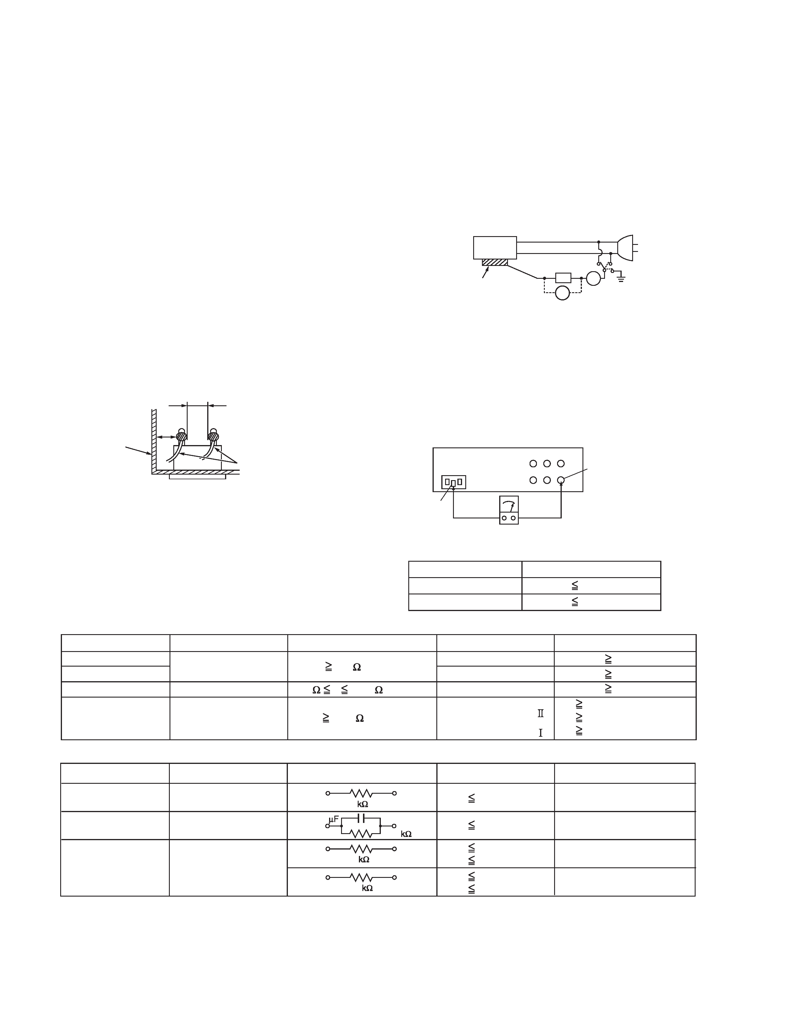
(3) Clearance distance
When replacing primary circuit components, confirm spec-
ified clearance distance (d), (d') between soldered termi-
nals, and between terminals and surrounding metallic
parts. See Fig.1-1-11 below.
Fig.1-1-8
(4) Leakage current test
Confirm specified or lower leakage current between earth
ground/power cord plug prongs and externally exposed ac-
cessible parts (RF terminals, antenna terminals, video and
audio input and output terminals, microphone jacks, ear-
phone jacks, etc.).
Measuring Method : (Power ON)Insert load Z between
earth ground/power cord plug prongs and externally ex-
posed accessible parts. Use an AC voltmeter to measure
across both terminals of load Z. See Fig.1-1-9 and follow-
ing Fig.1-1-12.
Fig.1-1-9
(5) Grounding (Class 1 model only)
Confirm specified or lower grounding impedance between
earth pin in AC inlet and externally exposed accessible
parts (Video in, Video out, Audio in, Audio out or Fixing
screw etc.).Measuring Method:
Connect milli ohm meter between earth pin in AC inlet and
exposed accessible parts. See Fig.1-1-10 and grounding
specifications.
Fig.1-1-10
Fig.1-1-11
Fig.1-1-12
NOTE :
These tables are unofficial and for reference only. Be sure to confirm the precise values for your particular country and locality.
Chassis
Power cord
primary wire
d'
d
ab
c
V
A
Externally
exposed
accessible part
Z
Exposed accessible part
Grounding Specifications
AC inlet
Region
USA & Canada
Europe & Australia
Grounding Impedance (Z)
Z
0.1 ohm
Z
0.5 ohm
Earth pin
MIlli ohm meter
AC Line Voltage
Region
Japan
Europe & Australia
R 1 M /500 V DC
USA & Canada
1 M
R 12 M /500 V DC
R 10 M /500 V DC
Insulation Resistance (R)
Dielectric Strength
Clearance Distance (d), (d')
100 V
100 to 240 V
110 to 130 V
110 to 130 V
200 to 240 V
AC 1 kV 1 minute
AC 1.5 kV 1 minute
AC 1 kV 1 minute
(Class )
(Class )
AC 3 kV 1 minute
AC 1.5 kV 1 minute
d, d'
3 mm
d, d'
4 mm
d, d'
3.2 mm
d'
8 m m (Power cord)
d'
6 m m (Primary wire)
d
4 m m
AC Line Voltage
Region
Japan
Europe & Australia
USA & Canada
Load Z
Leakage Current (i)
a, b, c
100 V
110 to 130 V
110 to 130 V
220 to 240 V
i
1 mA rms
i
0.5 mA rms
i
0.7 mA peak
i
2 mA dc
i
0.7 mA peak
i
2 mA dc
Exposed accessible parts
Exposed accessible parts
Antenna earth terminals
Other terminals
1
1.5
2
50
0.15
(No.YD007)1-5
SECTION 2
SPECIFIC SERVICE INSTRUCTIONS
2.1
Different table of features
The following table indicates main different points between models HR-J4020UA, HR-J7020UA, HR-J4020UB and HR-J7020UM.
NOTE:
Mark
is same as left.
2.2
Service position
This unit has been designed so that the Mechanism and Main
board assemblies can be removed together from the chassis as-
sembly. Before diagnosing or servicing the circuit boards, take
out the major parts from the chassis assembly.
2.2.1 How to set the "Service position"
(1) Refer to the disassembly procedure and perform the disas-
sembly of the major parts before removing the Mechanism
assembly.
(2) Remove the screws that fix the Mechanism assembly to
the Chassis assembly. If any other screws are used to fix
the boards, remove them also.
(3) Remove the combined Mechanism and Main board assem-
blies.
(4) If any other major parts are used, remove them also.
(5) Connect the wires and connectors of the major parts that
have been removed in steps (1) to (4). (Refer to Fig. 2-2a.)
(6) Place the combined Mechanism, Main board and other
board assemblies upside down.
(7) Insert the power cord plug into the power outlet and then
proceed with the diagnostics and servicing of the board as-
sembly.
Note:
· Before inserting the power cord plug into the power out-
let, make sure that none of the electrical parts are able
to short-circuit between the workbench and the board
assembly.
· For the disassembly procedure of the major parts and
details of the precautions to be taken, see "3.1 Remov-
ing the major parts".
· If there are wire connections from the Main board and
Mechanism assemblies to the other major parts, be sure
to remove them (including wires connected to the major
parts) first before performing step (2).
· When carrying out diagnosis and repair of the Main
board assembly in the "Service position", be sure to
ground both the Main board and Mechanism assem-
blies. If they are improperly grounded, there may be
noise on the playback picture or FDP counter display
may move even when the mechanism is kept in an inop-
erative status.
· In order to diagnose the playback or recording of the cas-
sette tape, set the Mechanism assembly to the required
mode before placing it upside down. If the mechanism
mode is changed (including ejection) while it is in an up-
side down position the tape inside may be damaged.
· For some models, the mechanism and board assem-
blies are attached by connectors only. When carrying
out a diagnosis or repair of the boards in the "Service
position", make sure that the connectors are not dis-
connected.
HR-J4020UA
HR-J7020UA
HR-J4020UB
HR-J7020UM
POWER PLUG
IRAM
BRAZIL PLUG
SASO
HiFi HEAD
NOT USED
USED
NOT USED
USED
SHUTTLE SEARCH
(LATCH)-PAL
SP
× 7, LP × 7
NOT USED
VIDEO SYSTEM
PAL-N (SP,LP) /
NTSC (SP,EP)
PAL-M/NTSC (SP,EP)
NTSC
PAL-M PB
(SP,EP)
PAL
PAL-M PB(SP,LP)
NTSC (SP,EP)
SQPB
NTSC (SP,EP)
PAL-M/NTSC (SP,EP)
NTSC (SP,EP)
RECORDING &
PLAYBACK SPEED
NTSC:REC:SP/EP,
PLAY:SP/LP/EP
PAL-N:REC:SP/LP,
PLAY:SP/LP
REC:SP/EP,
PLAY:SP/LP/EP
REAR AV INPUT TERMINAL
USED
NOT USED
STEREO DECODER
NOT USED
MTS
NOT USED
MTS
RF OUT CH/RF OUT SYSTEM [INITIAL]
[3CH],4CH,OFF/[N]
[3CH],4CH,OFF/[M]
CLOCK / SUMMER TIME ADJ.
24H / USED(MANUAL)
12H / NOT USED
AUTO SP
EP(LP) TIMER
SP
LP
SP
EP
DISPLAY TYPE
4-DOT LED
4-DIGIT LED
4-DOT LED
4-DIGIT LED
POWER OFF DIMMER
NOT USED
USED
NOT USED
USED
OSD LANGUAGES
SPANISH, ENGLISH
PORTUGUESE
SPANISH, ENGLISH
DISPLAY OFF
NOT USED
USED(with MENU)
NOT USED
USED(with MENU)