SERVICE MANUAL
No.82903
January 2002
HR-J3009UM/HR-J4009UM
VIDEO CASSETTE RECORDER
SPECIFICATIONS (The specifications shown pertain specifically to the model HR-J4009UM.)
This service manual is printed on 100% recycled paper.
COPYRIGHT © 2002 VICTOR COMPANY OF JAPAN, LTD
AUDIO
POWER
CH
REC
TV/VCR
TIMER
REC
POWER
REW
PLAY
FF
STOP/EJECT
VIDEO
MENU
REC
REW
FF
CH
(AUX)
ENTER
12
3
45
6
7
0
89
SET
TV/VCR
TIMER
SP/EP
DISPLAY
CANCEL
C.RESET
TV CH
TV VOL
INPUT
+
+
+
+
PAUSE
PLAY
STOP
TV POWER
POWER
GENERAL
Power requirement
Power consumption
Power on
Power off
Temperature
Operating
Storage
Operating position
Dimensions (W x H x D)
Weight
Format
Maximum recording time
SP
EP
VIDE O/AUDIO
Signal system
Recording/Playback
system
Signal-to-noise ratio
Horizontal resolution
Frequency range
Normal audio
Input/Output
TUNER
Tuning system
Channel coverage
VHF
UHF
CATV
R F output
TIMER
Clock reference
Program capacity
Memory backup for timer
ACCESSO RIES
Provided accessories
Specifications shown are for S P mode unless specified otherwise.
E. & O.E. Design and specifications subject to change without notice.
: AC 110 V-220 V~, 50Hz/60 Hz
:9 W
: 2.0 W
:5
°C to 40°C (41°F to 104°F)
:20
°C to 60°C (4°F to140°F)
: Horizontal only
: 360 mm x 95 mm x 224 mm
: 3.2 kg
: VHS NTSC standard
: 210 min. with ST -210 video cassette
: 630 min. with ST -210 video cassette
: NTSC-type color signal and
E IA monochrome signal, 525 lines/60 fields
: DA-4
(Double Azimuth) head helical scan system
: 42 dB
: 230 lines
: 100 Hz to 10,000 Hz
: RC A connectors (IN x 1, OUT x 1)
: Frequenc y-synthesized tuner
: Channels 213
: Channels 1469
: 113 Channels
: Channel 3 or 4 (switchable; preset to
Channel 3 when shipped) 75 ohms,
unbalanced
: Quartz
: 1-month programmable timer/8 programs
: Approx. 18 hours
: R F cable (F-type),
Infrared remote control unit,
"AAA" battery x 2, Conversion plug
HR-J3009UM/J4009UM
V15C1P/V15C1


TABLE OF CONTENTS
Section
Title
Page
Section
Title
Page
Important Safety Precautions
INSTRUCTIONS
DISASSEMBLY INSTRUCTION
1.REMOVAL OF MECHANICAL PARTS AND
P.C.BOARDS .................................................................. 1-1
1-1
TOP CABINET AND FRONT CABINET .................. 1-1
1-2
FLAP ....................................................................... 1-1
1-3
DECK CHASSIS ..................................................... 1-1
1-4
SYSCON PCB ......................................................... 1-1
2.REMOVAL OF DECK PARTS ......................................... 1-2
2-1
TOP BRACKET ....................................................... 1-2
2-2
CASSETTE HOLDER ASS'Y .................................. 1-2
2-3
CASSETTE SIDE L/R ............................................. 1-2
2-4
LINK UNIT ............................................................... 1-2
2-5
LINK LEVER/FLAP LEVER ..................................... 1-2
2-6
LOADING MOTOR/WORM ..................................... 1-3
2-7
TENSION ASS'Y ..................................................... 1-3
2-8
T BRAKE ARM/T BRAKE BAND ............................. 1-4
2-9
S REEL/T REEL/IDLER ARM ASS'Y/IDLER GEAR ........ 1-4
2-10 CASSETTE OPENER/PINCH ROLLER
BLOCK/P5 ARM ASS'Y ........................................... 1-5
2-11 A/C HEAD ............................................................... 1-5
2-12 FE HEAD(RECORDER ONLY) ............................... 1-5
2-13 AHC ASS'Y/CYLINDER UNIT ASS'Y ...................... 1-5
2-14 CAPSTAN DD UNIT ................................................ 1-6
2-15 MAIN CAM/PINCH ROLLER CAM/JOINT GEAR ............ 1-6
2-16 LOADING GEAR S/T UNIT .............................................. 1-6
2-17 CLUTCH ASS'Y/RING SPRING/
CLUTCH LEVER/CLUTCH GEAR ................................... 1-7
2-18 CASSETTE GUIDE POST/
INCLINED BASE S/T UNIT/P4 CAP ................................ 1-7
3.REMOVAL AND INSTALLATION OF FLAT PACKAGE IC ........ 1-8
REMOVAL ........................................................................ 1-8
INSTALLATION ................................................................ 1-9
KEY TO ABBREVIATIONS ............................................. 1-10
PREVENTIVE CHECKS AND SERVICE INTERVALS .... 1-12
CLEANING ...................................................................... 1-12
SERVICE MODE LIST ..................................................... 1-13
SERVICING FIXTURES AND TOOLS ............................. 1-13
MECHANISM ADJUSTMENT PARTS LOCATION GUIDE ....... 1-13
MECHANICAL ADJUSTMENTS
TAPE REMOVAL METHOD AT NO POWER SUPPLY .... 1-14
1.CONFIRMATION AND ADJUSTMENT ......................... 1-14
1-1
CONFIRMATION AND ADJUSTMENT OF
TENSION POST POSITION ................................. 1-14
1-2
CONFIRMATION OF PLAYBACK TORQUE AND
BACK TENSION TORQUE DURING PLAY BACK .. 1-14
1-3
CONFIRMATION OF VSR TORQUE .................... 1-14
1-4
CONFIRMATION OF REEL BRAKE TORQUE ..... 1-15
2.CONFIRMATION AND ADJUSTMENT OF
TAPE RUNNING MECHANISM .................................... 1-15
2-1
GUIDE ROLLER ................................................... 1-15
2-2
CONFIRMATION AND ADJUSTMENT OF
AUDIO/CONTROL HEAD ..................................... 1-16
2-3
TAPE RUNNING ADJUSTMENT(X-VALUE ADJUSTMENT) ... 1-16
ELECTRICAL ADJUSTMENTS
1.BASIC ADJUSTMENT .................................................. 1-17
1-1
SWITCHING POINT .............................................. 1-17
ELECTRICAL ADJUSTMENT PARTS LOCATION GUIDE ........ 1-17
IC DESCRIPTIONS ......................................................... 1-18
SERVO TIMING CHART ................................................. 1-21
MECHANISM TIMING CHART ........................................ 1-22
TROUBLESHOOTING GUIDE
POWER DOES NOT TURN ON .............................................. 1-23
POWER SHUTS OFF .................................................... 1-24
CYLINDER NOT ROTATING DURING PLAYBACK AND RECODRDING .. 1-26
CASSETTE IN AND DOWN, UNIT HAS NO FUNCTIONS ..... 1-26
FF/REW DO NOT WORK .............................................. 1-27
AUDIO SHAKES ............................................................ 1-27
CASSETTE TAPE IS NOT ACCEPTED ......................... 1-28
WHEN INSERTING CASSETTE, IT EJECTS IMMEDIATELY .. 1-30
TAPE LOADING IS OK, BUT UNLOADS IMMEDIATELY .. 1-32
CAPSTAN DD MOTOR NOT ROTATING ...................... 1-33
PLAYBACK PICTURE JITTERS HORIZONTALLY ........ 1-34
PLAYBACK PICTURE SHAKES .................................... 1-34
AUTO TRACKING DOES NOT OPERATE .................... 1-35
WHEN PLAYBACK, FAST FORWARD OR REWIND MODE IS ACTIVATED,
UNIT STOPS IMMEDIATELY ..................................................... 1-35
PLAYBACK PICTURE JITTERS VERTICALLY ............. 1-36
NO PLAYBACK PICTURE ............................................. 1-37
NO PICTURE DURING PLAYBACK .............................. 1-38
NO COLOR DURING SELF RECORDING AND PLAYBACK . 1-38
PLAYBACK PICTURE NOISY(EVEN AFTER CLEANING HEADS) ... 1-39
NO NORMAL AUDIO ON PLAYBACK ........................... 1-40
AUDIO CAN NOT BE RECORDED ............................... 1-41
RECORDING MECHANISM WORKS,
BUT NO VIDEO RECORDED FROM INPUT JACK OR TUNER .. 1-42
NO E-E(NO VIDEO FROM TUNER) .............................. 1-43
NO E-E AUDIO(MONO) ................................................. 1-44
NO TUNER AUDIO(MONO) ........................................... 1-45
CHARTS AND DIAGRAMS
INTERCONNECTION DIAGRAM [HR-J3009UM] .............. 2-1
Y/C/AUDIO/CCD/HEAD AMP SCHEMATIC DIAGRAM [HR-J3009UM] ... 2-3
SYSTEM CONTROL/SERVO SCHEMATIC DIAGRAM [HR-J3009UM] ... 2-5
POWER SCHEMATIC DIAGRAM [HR-J3009UM] ............. 2-7
TUNER SCHEMATIC DIAGRAM [HR-J3009UM] ................ 2-9
OPERATION SCHEMATIC DIAGRAM [HR-J3009UM] ......... 2-11
SYSCON CIRCUIT BOARD(INSERTED PARTS) [HR-J3009UM] .. 2-13
SYSCON CIRCUIT BOARD(CHIP MOUNTED PARTS) [HR-J3009UM] ... 2-15
WAVEFORMS [HR-J3009UM] ......................................... 2-18
Y/C/AUDIO/HEAD AMP BLOCK DIAGRAM [HR-J3009UM] ... 2-19
SYSTEM CONTROL/SERVO BLOCK DIAGRAM [HR-J3009UM] ... 2-21
TUNER BLOCK DIAGRAM [HR-J3009UM] ..................... 2-23
OPERATION BLOCK DIAGRAM [HR-J3009UM] ............ 2-25
INTERCONNECTION DIAGRAM [HR-J4009UM] ............ 2-27
Y/C/AUDIO/CCD/HEAD AMP SCHEMATIC DIAGRAM [HR-J4009UM] 2-29
SYSTEM CONTROL/SERVO SCHEMATIC DIAGRAM [HR-J4009UM] 2-31
POWER SCHEMATIC DIAGRAM [HR-J4009UM] ........... 2-33
TUNER SCHEMATIC DIAGRAM [HR-J4009UM] .............. 2-35
OPERATION SCHEMATIC DIAGRAM [HR-J4009UM] ......... 2-37
SYSCON CIRCUIT BOARD(INSERTED PARTS) [HR-J4009UM] .. 2-39
SYSCON CIRCUIT BOARD(CHIP MOUNTED PARTS) [HR-J4009UM] ... 2-41
WAVEFORMS [HR-J4009UM] ......................................... 2-44
Y/C/AUDIO/HEAD AMP BLOCK DIAGRAM [HR-J4009UM] ... 2-45
SYSTEM CONTROL/SERVO BLOCK DIAGRAM [HR-J4009UM] ... 2-47
TUNER BLOCK DIAGRAM [HR-J4009UM] ..................... 2-49
OPERATION BLOCK DIAGRAM [HR-J4009UM] ............ 2-51
PARTS LIST
3.1
PACKING AND ACCESSORY ASSEMBLY <M1> ..... 3-1
3.2
FINAL ASSEMBLY <M2> [HR-J3009UM] ................. 3-2
3.3
FINAL ASSEMBLY <M2> [HR-J4009UM] ................. 3-3
3.4
MECHANISM ASSEMBLY <M4> ............................... 3-4
3.5
ELECTRICAL PARTS LIST [HR-J3009UM] ............... 3-7
SYSCON BOARD ASSEMBLY <03> [HR-J3009UM] ... 3-7
3.6
ELECTRICAL PARTS LIST [HR-J4009UM] ............. 3-10
SYSCON BOARD ASSEMBLY <03> [HR-J4009UM] .. 3-10
Reference .......................................................................... 4-1
GENERAL SPECIFICATIONS [HR-J3009UM] .................. 4-1
GENERAL SPECIFICATIONS [HR-J4009UM] .................. 4-7
HR-J3009UM
HR-J4009UM
POWER VOLTAGE
120 V 60 Hz
110-220 V 50/60 Hz
TIMER BACK-UP (at Power off mode)
5 second
18 Hours
The following table lists the differing points between Models HR-J3009UM and HR-J4009UM.
MODEL
ITEM
Important Safety Precautions
Prior to shipment from the factory, JVC products are strictly inspected to conform with the recognized product safety and electrical codes
of the countries in which they are to be sold. However, in order to maintain such compliance, it is equally important to implement the
following precautions when a set is being serviced.
Fig.1
1. Locations requiring special caution are denoted by labels and
inscriptions on the cabinet, chassis and certain parts of the
product. When performing service, be sure to read and com-
ply with these and other cautionary notices appearing in the
operation and service manuals.
2. Parts identified by the
symbol and shaded (
) parts are
critical for safety.
Replace only with specified part numbers.
Note: Parts in this category also include those specified to com-
ply with X-ray emission standards for products using
cathode ray tubes and those specified for compliance
with various regulations regarding spurious radiation
emission.
3. Fuse replacement caution notice.
Caution for continued protection against fire hazard.
Replace only with same type and rated fuse(s) as specified.
4. Use specified internal wiring. Note especially:
1) Wires covered with PVC tubing
2) Double insulated wires
3) High voltage leads
5. Use specified insulating materials for hazardous live parts.
Note especially:
1) Insulation Tape
3) Spacers
5) Barrier
2) PVC tubing
4) Insulation sheets for transistors
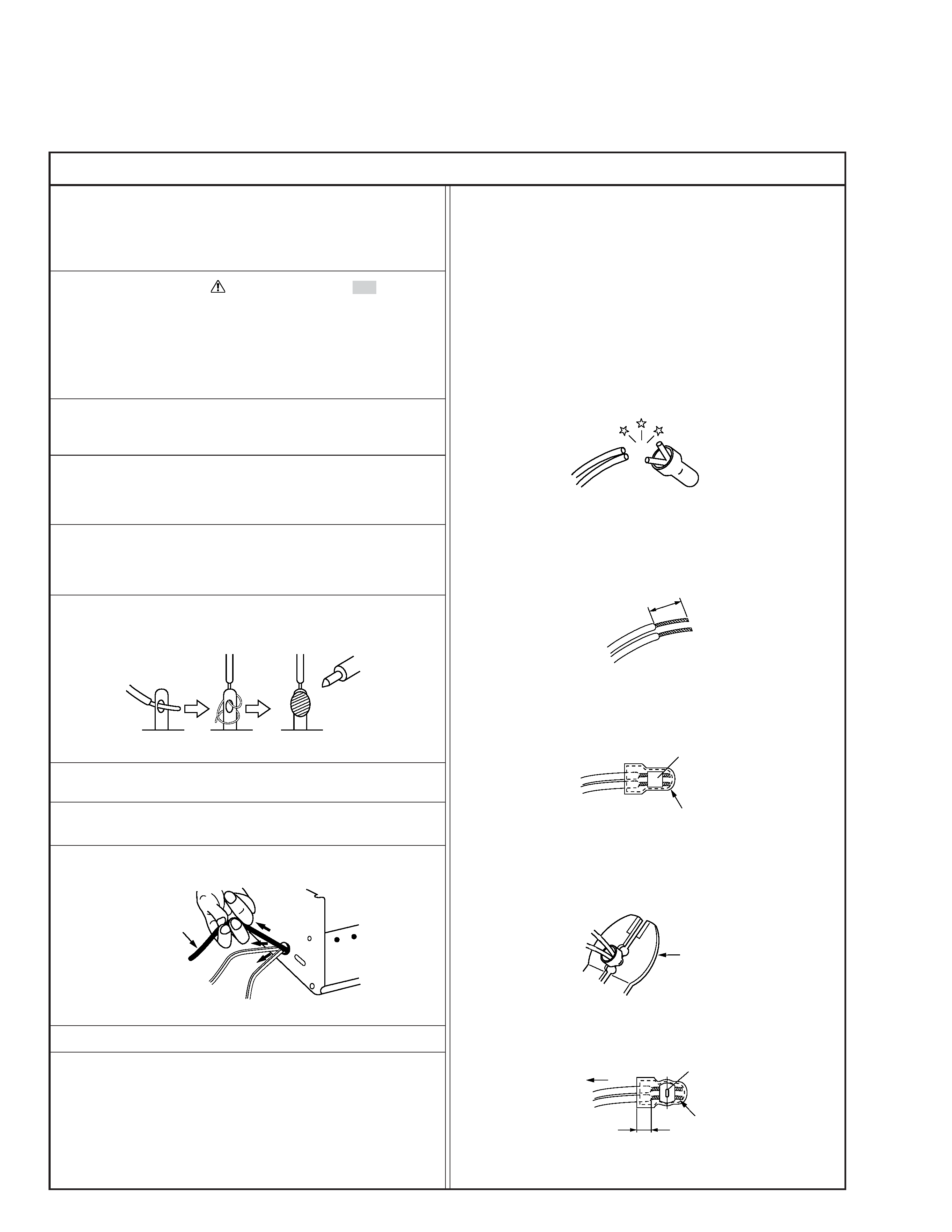
6. When replacing AC primary side components (transformers,
power cords, noise blocking capacitors, etc.) wrap ends of
wires securely about the terminals before soldering.
Power cord
Fig.2
10. Also check areas surrounding repaired locations.
11. Products using cathode ray tubes (CRTs)
In regard to such products, the cathode ray tubes themselves,
the high voltage circuits, and related circuits are specified for
compliance with recognized codes pertaining to X-ray emission.
Consequently, when servicing these products, replace the cath-
ode ray tubes and other parts with only the specified parts.
Under no circumstances attempt to modify these circuits.
Unauthorized modification can increase the high voltage value
and cause X-ray emission from the cathode ray tube.
12. Crimp type wire connector
In such cases as when replacing the power transformer in sets
where the connections between the power cord and power
transformer primary lead wires are performed using crimp type
connectors, if replacing the connectors is unavoidable, in or-
der to prevent safety hazards, perform carefully and precisely
according to the following steps.
1) Connector part number : E03830-001
2) Required tool : Connector crimping tool of the proper type
which will not damage insulated parts.
3) Replacement procedure
(1) Remove the old connector by cutting the wires at a point
close to the connector.
Important : Do not reuse a connector (discard it).
Fig.7
cut close to connector
Fig.3
(2) Strip about 15 mm of the insulation from the ends of
the wires. If the wires are stranded, twist the strands to
avoid frayed conductors.
15 mm
Fig.4
(3) Align the lengths of the wires to be connected. Insert
the wires fully into the connector.
Connector
Metal sleeve
Fig.5
(4) As shown in Fig.6, use the crimping tool to crimp the
metal sleeve at the center position. Be sure to crimp fully
to the complete closure of the tool.
1
Precautions during Servicing
7. Observe that wires do not contact heat producing parts
(heatsinks, oxide metal film resistors, fusible resistors, etc.)
8. Check that replaced wires do not contact sharp edged or
pointed parts.
9. When a power cord has been replaced, check that 10-15 kg of
force in any direction will not loosen it.
1.25
2.0
5.5
Crimping tool
Fig.6
(5) Check the four points noted in Fig.7.
Not easily pulled free
Crimped at approx. center
of metal sleeve
Conductors extended
Wire insulation recessed
more than 4 mm
S40888-01
Safety Check after Servicing
Examine the area surrounding the repaired location for damage or deterioration. Observe that screws, parts and wires have been
returned to original positions, Afterwards, perform the following tests and confirm the specified values in order to verify compli-
ance with safety standards.
1. Insulation resistance test
Confirm the specified insulation resistance or greater between power cord plug prongs and
externally exposed parts of the set (RF terminals, antenna terminals, video and audio input
and output terminals, microphone jacks, earphone jacks, etc.). See table 1 below.
2. Dielectric strength test
Confirm specified dielectric strength or greater between power cord plug prongs and exposed
accessible parts of the set (RF terminals, antenna terminals, video and audio input and output
terminals, microphone jacks, earphone jacks, etc.). See table 1 below.
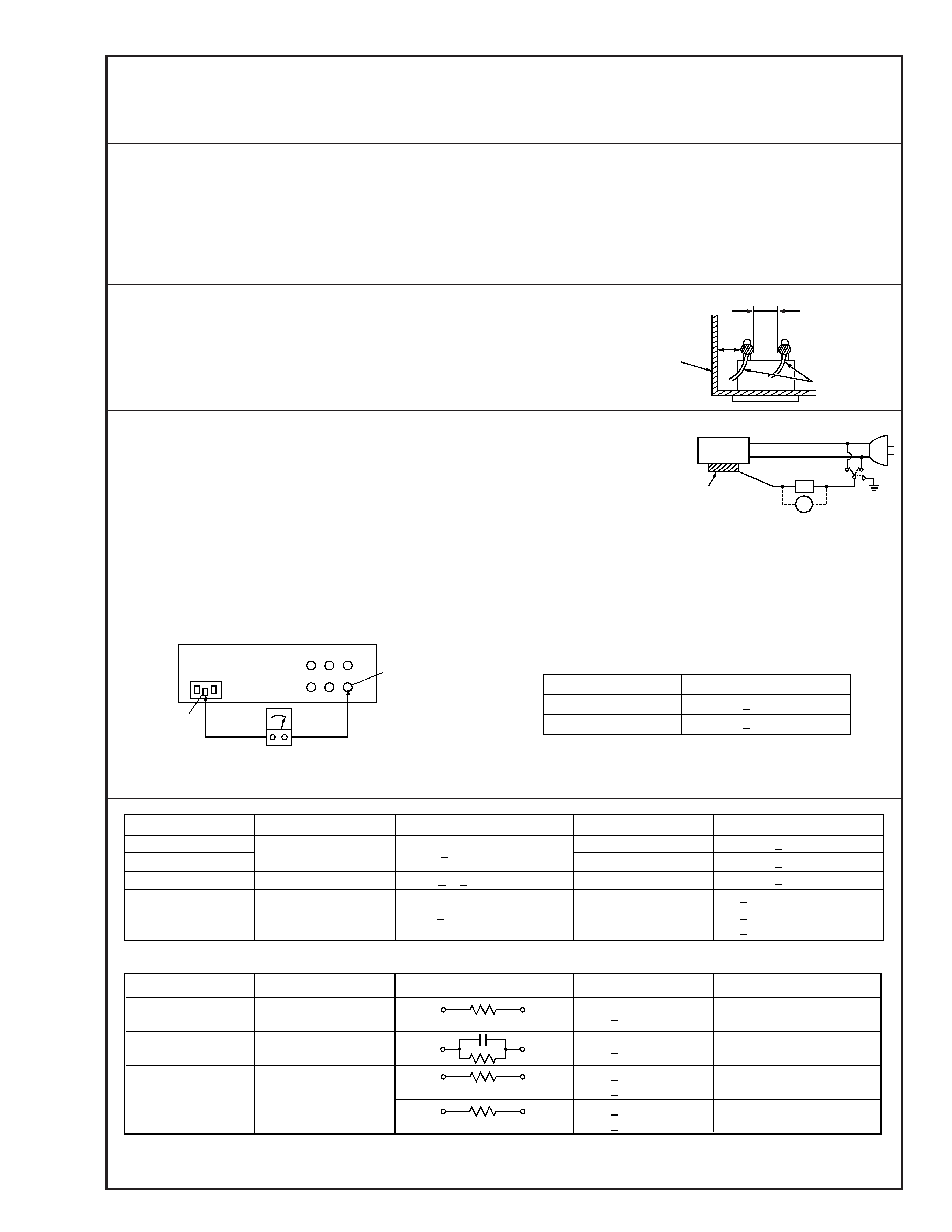
3. Clearance distance
When replacing primary circuit components, confirm specified clearance distance (d), (d') be-
tween soldered terminals, and between terminals and surrounding metallic parts. See table 1
below.
4. Leakage current test
Confirm specified or lower leakage current between earth ground/power cord plug prongs
and externally exposed accessible parts (RF terminals, antenna terminals, video and audio
input and output terminals, microphone jacks, earphone jacks, etc.).
Measuring Method : (Power ON)
Insert load Z between earth ground/power cord plug prongs and externally exposed accessi-
ble parts. Use an AC voltmeter to measure across both terminals of load Z. See figure 9 and
following table 2.
5. Grounding (Class 1 model only)
Confirm specified or lower grounding impedance between earth pin in AC inlet and externally exposed accessible parts (Video in,
Video out, Audio in, Audio out or Fixing screw etc.).
Measuring Method:
Connect milli ohm meter between earth pin in AC inlet and exposed accessible parts. See figure 10 and grounding specifications.
d'
d
Chassis
Power cord,
primary wire
Region
USA & Canada
Europe & Australia
Grounding Impedance (Z)
Z
0.1 ohm
Z
0.5 ohm
AC inlet
Earth pin
Exposed accessible part
Milli ohm meter
Grounding Specifications
Fig. 10
ab
c
V
Externally
exposed
accessible part
Z
Fig. 9
Fig. 8
Clearance Distance (d), (d')
d, d'
3 mm
d, d'
4 mm
d, d'
3.2 mm
1 M
R 12 M/500 V DC
Dielectric Strength
AC 1 kV 1 minute
AC 1.5 kV 1 miute
AC 1 kV 1 minute
AC Line Voltage
100 V
100 to 240 V
110 to 130 V
110 to 130 V
200 to 240 V
Japan
USA & Canada
Europe & Australia
R
10 M
/500 V DC
Region
Insulation Resistance (R)
R
1 M
/500 V DC
AC 3 kV 1 minute
(Class
2)
AC 1.5 kV 1 minute
(Class
1)
d
4 mm
d'
8 mm (Power cord)
d'
6 mm (Primary wire)
Table 1 Specifications for each region
a, b, c
Leakage Current (i)
AC Line Voltage
100 V
110 to 130 V
110 to 130 V
220 to 240 V
Japan
USA & Canada
i
1 mA rms
Exposed accessible parts
Exposed accessible parts
Antenna earth terminals
Other terminals
i
0.5 mA rms
i
0.7 mA peak
i
2 mA dc
i
0.7 mA peak
i
2 mA dc
Europe & Australia
Region
Load Z
1 k
2 k
1.5 k
0.15
µF
50 k
Table 2 Leakage current specifications for each region
Note: These tables are unofficial and for reference only. Be sure to confirm the precise values for your particular country and locality.
2
S40888-01