SERVICE MANUAL
SPECIFICATIONS (The specifications shown pertain specifically to the model HR-J280EU/J281EU/J289EU/J480EU)
No.82845
February 2001
HR-J281EU/J289EU
VIDEO CASSETTE RECORDER
GENERAL
Power requirement : AC 220 V 240 Vd, 50 Hz/60 Hz
Power consumption
Power on
: 14 W
Power off
: 3.4 W
Temperature
Operating
: 5
°C to 40°C
Storage
: 20
°C to 60°C
Operating position : Horizontal only
Dimensions (WxHxD)
: 360 mm x 94 mm x 278 mm
Weight
: 3.2 kg
Format
: VHS PAL standard
Maximum recording time
(SP)
: 240 min. with E-240 video cassette
(LP) [HR-J480EU only]
: 480 min. with E-240 video cassette
VIDEO/AUDIO
Signal system
: PAL-type colour signal and CCIR
monochrome signal, 625 lines
50 fields
Recording system
[HR-J480EU]
: DA4 (Double Azimuth) head helical
scan system
[HR-J280/281/289EU]
: Rotary two-head herical scan
system
Signal-to-noise ratio: 45 dB
Horizontal resolution
: 250 lines
Frequency range
: 70 Hz to 10,000 Hz
Input/Output
: 21-pin SCART connectors :
IN/OUT x 1, IN/DECODER x 1
TUNER/TIMER
TV channel storage capacity
: 99 positions (+AUX position)
Tuning system
: Frequency synthesized tuner
Channel coverage : VHF 47MHz 89MHz/
104MHz 300MHz/
302MHz 470MHz
UHF 470MHz 862MHz
Aerial output
: UHF channels 22 69 (Adjustable)
Memory backup time
: Approx. 10 min.
ACCESSORIES
Provided accessories
: RF cable,
Infrared remote control unit,
"R6" battery x 2
Specifications shown are for SP mode unless otherwise
specified.
E.& O.E. Design and specifications subject to change without
notice.
Regarding service information other than these sections, refer to the HR-J280EU service manual (No.82844).
Also, be sure to note important safety precautions provided in the service manual.
SERVICE MANUAL
VICTOR COMPANY OF JAPAN, LIMITED
VIDEO DIVISION
Printed in Japan
S40894
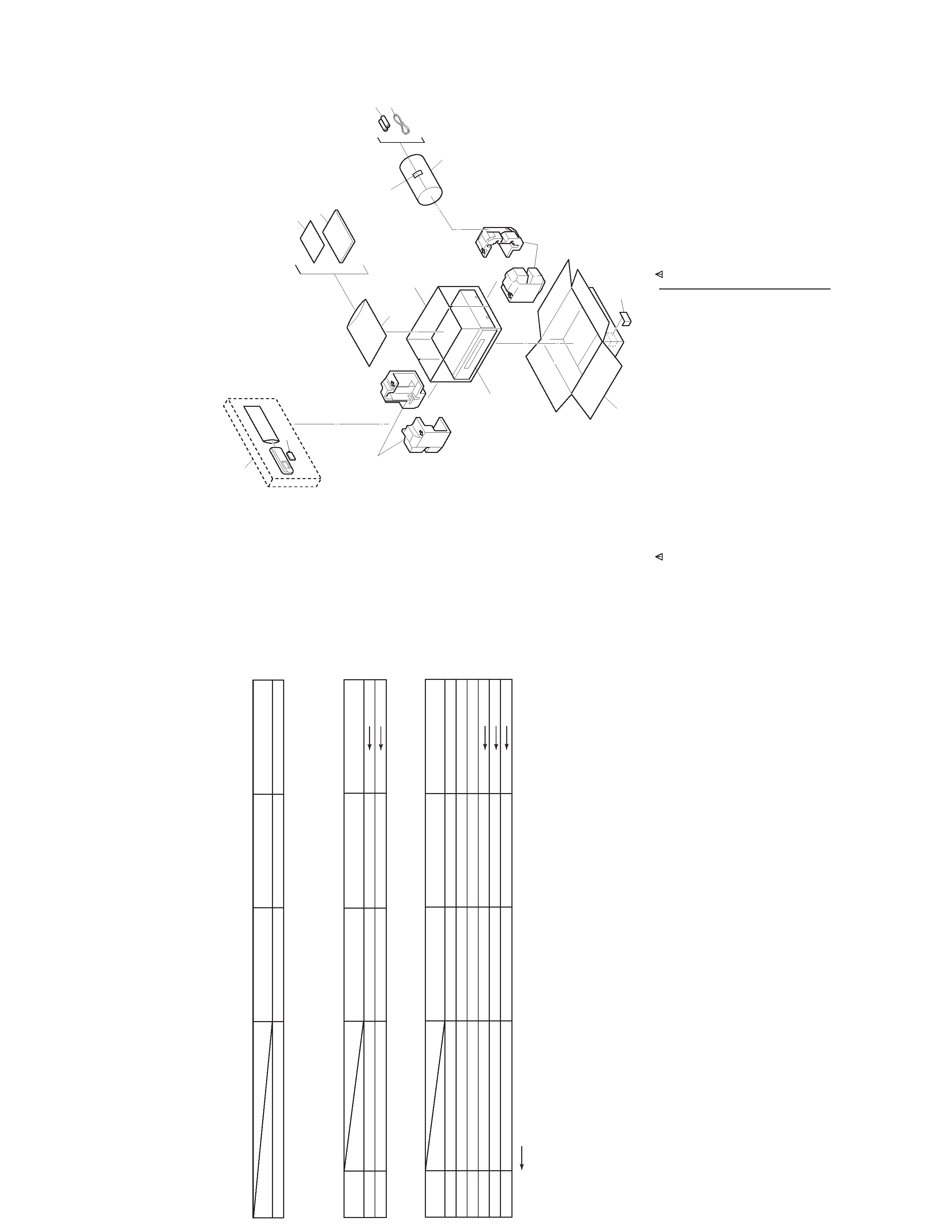
TABLE OF CONTENTS
DIFFERENT TABLE .................................................................................................................................................. (1 only)
5. PARTS LIST
5.1 PACKING AND ACCESSORY ASSEMBLY <M1> ................................................................................................. 5-1
The following table indicate different parts number between models HR-J280EU, HR-J281EU and HR-J289EU.
PACKING AND ACCESSORY ASSEMBLY<M1>
REF
NO.
!
MODEL
HR-J280EU
HR-J281EU
ITEM
306
REMOTE CONTROL UNIT
LP20878-002A
LP20878-003A
306A
COVER(BATTERY)
LP40610-002A
LP40610-001A
HR-J289EU
The following table indicate main different points between models HR-J280EU, HR-J281EU and HR-J289EU.
MODEL
HR-J280EU
HR-J281EU
ITEM
FRONT PANEL COLOR
PURE SILVER
BLACK
BLACK & GOLDLETTER
HR-J289EU
FINAL ASSEMBLY<M2>
REF
NO.
!
MODEL
HR-J280EU
HR-J281EU
ITEM
! 501
FRONT PANEL ASSEMBLY
LP10293-032B
LP10293-033B
LP10293-038A
501A
CASSETE DOOR
LP20868-033A
LP20868-034A
LP20868-037A
501D
DISPLAY WINDOW
LP20869-088B
LP20869-089B
LP20869-098A
501E
ORNAMENT
LP30649-005A
LP30649-002A
! 502
TOP COVER
PQ11898-52-23
PQ11898-50-23
503
SCREW,X4,TOP COVER(SIDE)
QYTDSF3010R
QYTDSF3010M
HR-J289EU
Note: Mark
is same as left.
SECTION 5
PARTS LIST
SAFETY PRECAUTION
Parts identified by the
! symbol are critical for safety. Replace only with specified part numbers.
5.1
PACKING AND ACCESSORY ASSEMBLY
<M1>
The instruction manual to be provided with this product will differ according to the destination.
******************************
PACKING AND ACCESSORY ASSEMBLY
<M1>
301
LP30897-001A
PACKING CASE
302
LP30898-001A
CUSHION ASSY
303
PQM30021-93
POLY BAG
306
LP20878-003A
REMOTE CONTROLLER
306 A
LP40610-001A
COVER(BATTERY)
307
--
BATTERY,X2("R6"TYPE)
308
QPC02202230P
POLY BAG
! 310
LPT0566-001A
INST.BOOK(EN)
!
LPT0566-002A
INST.BOOK(GE)
!
LPT0566-003A
INST.BOOK(FR)
!
LPT0566-004A
INST.BOOK(DU)
---------------
-----------------------
---------------------------------------------------- -
------------- ---
-----------------------
----------------------------------------------------- -
#
REF No. PART No.
PART NAME, DESCRIPTION
#
REF No.
PART No.
PART NAME, DESCRIPTION
!
LPT0566-005A
INST.BOOK(SP)
!
LPT0566-006A
INST.BOOK(IT)
!
LPT0566-007A
INST.BOOK(DA)
!
LPT0566-008A
INST.BOOK(FI)
!
LPT0566-009A
INST.BOOK(SW)
!
LPT0566-010A
INST.BOOK(NO)
!
LPT0566-011A
INST.BOOK(PT)
!
LPT0566-012A
INST.BOOK(GR)
!
LPT0566-013A
INST.BOOK(CZ)
!
LPT0566-014A
INST.BOOK(PO)
!
LPT0566-015A
INST.BOOK(HU)
311
QPC02503530P
POLY BAG
312
PEAC0300-02
RF CABLE
316
BT-54013-2
WARRANTY CARD
302
310
CABINET & CHASSIS ASSY
<M2>
306
306A
311
303
ADHESIVE
TAPE
307
312
308
302
301
SPEC OF BARCODE
316
5-1
E. & O.E. No.82845
(VP)-V14A11/A12
SPECIFICATIONS (The specifications shown pertain specifically to the model HR-J280EU/J281EU/J289EU/J480EU)
SERVICE MANUAL
No.82844
February 2001
HR-J280EK /EU/MS
VIDEO CASSETTE RECORDER
GENERAL
Power requirement : AC 220 V 240 Vd, 50 Hz/60 Hz
Power consumption
Power on
: 14 W
Power off
: 3.4 W
Temperature
Operating
: 5
°C to 40°C
Storage
: 20
°C to 60°C
Operating position : Horizontal only
Dimensions (WxHxD)
: 360 mm x 94 mm x 278 mm
Weight
: 3.2 kg
Format
: VHS PAL standard
Maximum recording time
(SP)
: 240 min. with E-240 video cassette
(LP) [HR-J480EU only]
: 480 min. with E-240 video cassette
VIDEO/AUDIO
Signal system
: PAL-type colour signal and CCIR
monochrome signal, 625 lines
50 fields
Recording system
[HR-J480EU]
: DA4 (Double Azimuth) head helical
scan system
[HR-J280/281/289EU]
: Rotary two-head herical scan
system
Signal-to-noise ratio: 45 dB
Horizontal resolution
: 250 lines
Frequency range
: 70 Hz to 10,000 Hz
Input/Output
: 21-pin SCART connectors :
IN/OUT x 1, IN/DECODER x 1
TUNER/TIMER
TV channel storage capacity
: 99 positions (+AUX position)
Tuning system
: Frequency synthesized tuner
Channel coverage : VHF 47MHz 89MHz/
104MHz 300MHz/
302MHz 470MHz
UHF 470MHz 862MHz
Aerial output
: UHF channels 22 69 (Adjustable)
Memory backup time
: Approx. 10 min.
ACCESSORIES
Provided accessories
: RF cable,
Infrared remote control unit,
"R6" battery x 2
Specifications shown are for SP mode unless otherwise
specified.
E.& O.E. Design and specifications subject to change without
notice.

TABLE OF CONTENTS
Section
Title
Page
Section
Title
Page
Important Safety Precautions
INSTRUCTIONS
1. DISASSEMBLY
1.1
Disassembly flow chart .............................................. 1-1
1.2
How to read the disassembly and assembly ............. 1-1
1.3
Disassembly /assembly method ................................ 1-1
1.4
Service position ......................................................... 1-4
1.4.1 How to set the "Service position" .......................... 1-4
1.5
Mechanism service mode .......................................... 1-4
1.5.1 How to set the "Mechanism service mode" ........... 1-4
1.6
Jig RCU mode ........................................................... 1-4
1.6.1 Setting the Jig RCU mode .................................... 1-4
1.6.2 Setting the User RCU mode ................................. 1-4
1.7
Emergency display function ....................................... 1-5
1.7.1 Displaying the EMG information ........................... 1-5
1.7.2 Clearing the EMG history ...................................... 1-5
1.7.3 EMG content description ...................................... 1-6
1.7.4 EMG detail information <1> .................................. 1-7
1.7.5 EMG detail information <2> .................................. 1-8
2. MECHANISM ADJUSTMENT
2.1
Before starting repair and adjustment ....................... 2-1
2.1.1 Precautions ........................................................... 2-1
2.1.2 Checking for proper mechanical operations ......... 2-1
2.1.3 Manually removing the cassette tape ................... 2-1
2.1.4 Jigs and tools required for adjustment .................. 2-2
2.1.5 Maintenance and inspection ................................. 2-3
2.2
Replacement of major parts ...................................... 2-6
2.2.1 Before starting disassembling
(Phase matching between mechanical parts) ....... 2-6
2.2.2 How to set the "Mechanism assembling mode" .... 2-6
2.2.3 Cassette holder assembly .................................... 2-6
2.2.4 Pinch roller arm assembly .................................... 2-8
2.2.5 Guide arm assembly and press lever assembly ..... 2-8
2.2.6 A/C head ............................................................... 2-8
2.2.7 Loading motor ....................................................... 2-8
2.2.8 Capstan motor ...................................................... 2-9
2.2.9 Pole base assembly (supply or take-up side) ....... 2-9
2.2.10 Rotary encoder ................................................... 2-10
2.2.11 Clutch unit ........................................................... 2-10
2.2.12 Change lever assembly,direct gear,clutch gear
and coupling gear ............................................... 2-10
2.2.13 Link lever ............................................................ 2-11
2.2.14 Cassette gear,control cam and worm gear ......... 2-11
2.2.15 Control plate ....................................................... 2-11
2.2.16 Loading arm gear (supply or take-up side)
and loading arm gear shaft ................................. 2-12
2.2.17 Take-up lever,take-up head and control plate guide .... 2-13
2.2.18 Capstan brake assembly .................................... 2-13
2.2.19 Sub brake assembly (take-up side) .................... 2-13
2.2.20 Main brake assembly (take-up side),
reel disk (take-up side) and
main brake assembly (supply side) .................... 2-13
2.2.21 Tension brake assembly, reel disk (supply side)
and tension arm assembly .................................. 2-14
2.2.22 Idler lever, idler arm assembly ............................ 2-14
2.2.23 Stator assembly .................................................. 2-14
2.2.24 Rotor assembly ................................................... 2-14
2.2.25 Upper drum assembly ......................................... 2-15
2.3
Compatibility adjustment ......................................... 2-16
2.3.1 FM waveform linearity ......................................... 2-16
2.3.2 Height and tilt of the A/C head ............................ 2-17
2.3.3 A/C head phase (X-value) .................................. 2-17
2.3.4 Standard tracking preset ..................................... 2-18
2.3.5 Tension pole position .......................................... 2-18
3. ELECTRICAL ADJUSTMENT
3.1
Precaution ................................................................. 3-1
3.1.1 Required test equipments ..................................... 3-1
3.1.2 Required adjustment tools .................................... 3-1
3.1.3 Color (colour) bar signal,color (colour) bar pattern ...... 3-1
3.1.4 Switch settings and standard precautions ............ 3-1
3.2
Servo circuit ............................................................... 3-2
3.2.1 Switching point ...................................................... 3-2
3.2.2 Slow tracking preset ............................................. 3-2
3.3
Video circuit ............................................................... 3-2
3.3.1 Auto picture initial setting ...................................... 3-2
3.4
Syscon circuit [HR-J280EU] ...................................... 3-2
3.4.1 Timer clock ............................................................ 3-2
4. CHARTS AND DIAGRAMS
4.1
BOARD INTERCONNECTIONS ............................... 4-3
4.2
MAIN (VIDEO/AUDIO) SCHEMATIC DIAGRAM ....... 4-5
4.3
MAIN (ON SCREEN) SCHEMATIC DIAGRAM ......... 4-7
4.4
MAIN (SYSCON) SCHEMATIC DIAGRAM ............... 4-9
4.5
MAIN (SW.REG) SCHEMATIC DIAGRAM .............. 4-11
4.6
MAIN (TUNER/DEMOD) SCHEMATIC DIAGRAM ..... 4-13
4.7
MAIN (FRONT) AND MINI FRONT SCHEMATIC DIAGRAMS ... 4-15
4.8
MAIN (TERMINAL) SCHEMATIC DIAGRAM .......... 4-17
4.9
MAIN (SECAM) SCHEMATIC DIAGRAM
[HR-J280MS/J480MS] ............................................. 4-19
4.10 MAIN AND MINI FRONT CIRCUIT BOARDS .......... 4-21
4.11 FDP GRID ASSIGNMENT AND ANODE CONNECTION ...... 4-24
4.12 REMOTE CONTROLLER SCHEMATIC DIAGRAM .... 4-25
4.13 WAVEFORMS ......................................................... 4-26
4.14 VOLTAGE CHARTS ................................................ 4-27
4.15 CPU PIN FUNCTION .............................................. 4-28
4.16 SYSTEM CONTROL BLOCK DIAGRAM ................ 4-29
4.17 VIDEO BLOCK DIAGRAM ...................................... 4-31
4.18 AUDIO BLOCK DIAGRAM ...................................... 4-33
5. PARTS LIST
5.1
PACKING AND ACCESSORY ASSEMBLY <M1> ..... 5-1
5.2
FINAL ASSEMBLY <M2> ........................................... 5-2
5.3
MECHANISM ASSEMBLY <M4> ............................... 5-4
5.4
ELECTRICAL PARTS LIST ....................................... 5-6
MAIN BOARD ASSEMBLY <03> ............................... 5-6
A/C HEAD BOARD ASSEMBLY <12> ..................... 5-12
MINI FRONT BOARD ASSEMBLY <28> ................. 5-12
LOADING MOTOR BOARD ASSEMBLY <55> ....... 5-12
The following table lists the differing points between Models (HR-J280EK, HR-J280EU and HR-J280MS) in this series.
HR-J280EK
HR-J280EU
HR-J280MS
POWER PLUG
3PIN(CLASSII)
CEE(CLASSII)
CEE(CLASSII)
SHUTTLE SEARCH(LATCH)-PAL
SP,LPx9
SPx9
SPx9
VIDEO SYSTEM
PAL/NTPB ON PAL TV
PAL/MESECAM(MANUAL)
PAL/MESECAM/SECAM
/NTPB ON PAL TV
/NTPB ON PAL TV
RECORDING & PLAYBACK SPEED
SP,LP
SP
SP
HQ
WC,DE,YNR
WC,DE
WC,DE
TUNER(BROADCASTING STANDARD)
I
B/G,D/K
L,L',B/G
RF OUT CH/RF OUT SYSTEM[INITIAL]
22-69CH,OFF[AUTO]/I
22-69CH,OFF[AUTO]/G,K
NOT USED
VCR PLUS
VIDEOPLUS+
SHOWVIEW
SHOWVIEW
AUTO SP z EP(LP) TIMER
SP z LP
NOT USED
NOT USED
TIMER(VPS)
NOT USED
USED
NOT USED
LANGUAGE[INITIAL](OSD)
ENG
13LANGUAGE,[ENG]
FRE
MODEL
ITEM
Important Safety Precautions
Prior to shipment from the factory, JVC products are strictly inspected to conform with the recognized product safety and electrical codes
of the countries in which they are to be sold. However, in order to maintain such compliance, it is equally important to implement the
following precautions when a set is being serviced.
Fig.1
1. Locations requiring special caution are denoted by labels and
inscriptions on the cabinet, chassis and certain parts of the
product. When performing service, be sure to read and com-
ply with these and other cautionary notices appearing in the
operation and service manuals.
2. Parts identified by the
symbol and shaded (
) parts are
critical for safety.
Replace only with specified part numbers.
Note: Parts in this category also include those specified to com-
ply with X-ray emission standards for products using
cathode ray tubes and those specified for compliance
with various regulations regarding spurious radiation
emission.
3. Fuse replacement caution notice.
Caution for continued protection against fire hazard.
Replace only with same type and rated fuse(s) as specified.
4. Use specified internal wiring. Note especially:
1) Wires covered with PVC tubing
2) Double insulated wires
3) High voltage leads
5. Use specified insulating materials for hazardous live parts.
Note especially:
1) Insulation Tape
3) Spacers
5) Barrier
2) PVC tubing
4) Insulation sheets for transistors
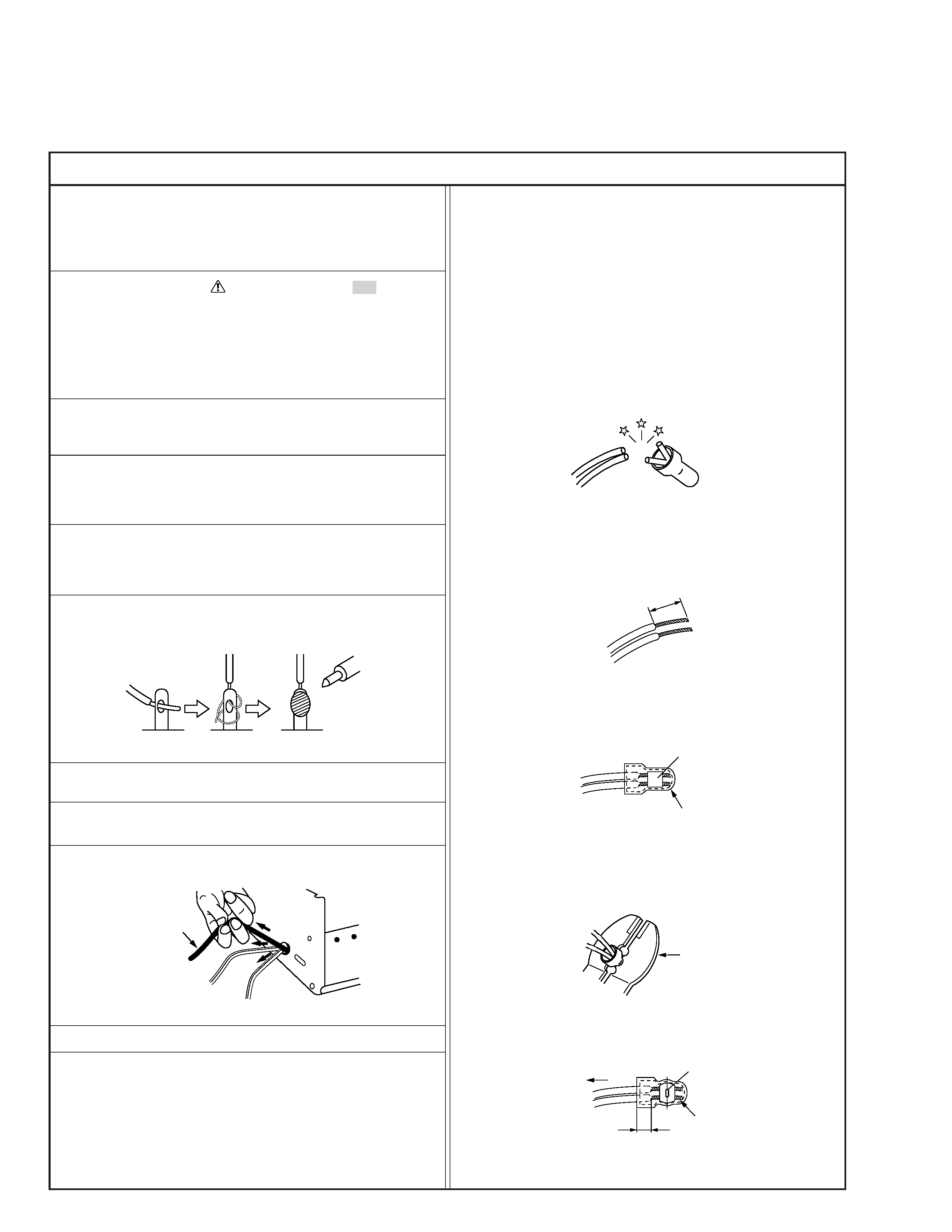
6. When replacing AC primary side components (transformers,
power cords, noise blocking capacitors, etc.) wrap ends of
wires securely about the terminals before soldering.
Power cord
Fig.2
10. Also check areas surrounding repaired locations.
11. Products using cathode ray tubes (CRTs)
In regard to such products, the cathode ray tubes themselves,
the high voltage circuits, and related circuits are specified for
compliance with recognized codes pertaining to X-ray emission.
Consequently, when servicing these products, replace the cath-
ode ray tubes and other parts with only the specified parts.
Under no circumstances attempt to modify these circuits.
Unauthorized modification can increase the high voltage value
and cause X-ray emission from the cathode ray tube.
12. Crimp type wire connector
In such cases as when replacing the power transformer in sets
where the connections between the power cord and power
transformer primary lead wires are performed using crimp type
connectors, if replacing the connectors is unavoidable, in or-
der to prevent safety hazards, perform carefully and precisely
according to the following steps.
1) Connector part number : E03830-001
2) Required tool : Connector crimping tool of the proper type
which will not damage insulated parts.
3) Replacement procedure
(1) Remove the old connector by cutting the wires at a point
close to the connector.
Important : Do not reuse a connector (discard it).
Fig.7
cut close to connector
Fig.3
(2) Strip about 15 mm of the insulation from the ends of
the wires. If the wires are stranded, twist the strands to
avoid frayed conductors.
15 mm
Fig.4
(3) Align the lengths of the wires to be connected. Insert
the wires fully into the connector.
Connector
Metal sleeve
Fig.5
(4) As shown in Fig.6, use the crimping tool to crimp the
metal sleeve at the center position. Be sure to crimp fully
to the complete closure of the tool.
1
Precautions during Servicing
7. Observe that wires do not contact heat producing parts
(heatsinks, oxide metal film resistors, fusible resistors, etc.)
8. Check that replaced wires do not contact sharp edged or
pointed parts.
9. When a power cord has been replaced, check that 10-15 kg of
force in any direction will not loosen it.
1.25
2.0
5.5
Crimping tool
Fig.6
(5) Check the four points noted in Fig.7.
Not easily pulled free
Crimped at approx. center
of metal sleeve
Conductors extended
Wire insulation recessed
more than 4 mm
S40888-01