SERVICE MANUAL
No. 82722
May 1999
COPYRIGHT © 1999 VICTOR COMPANY OF JAPAN, LTD.
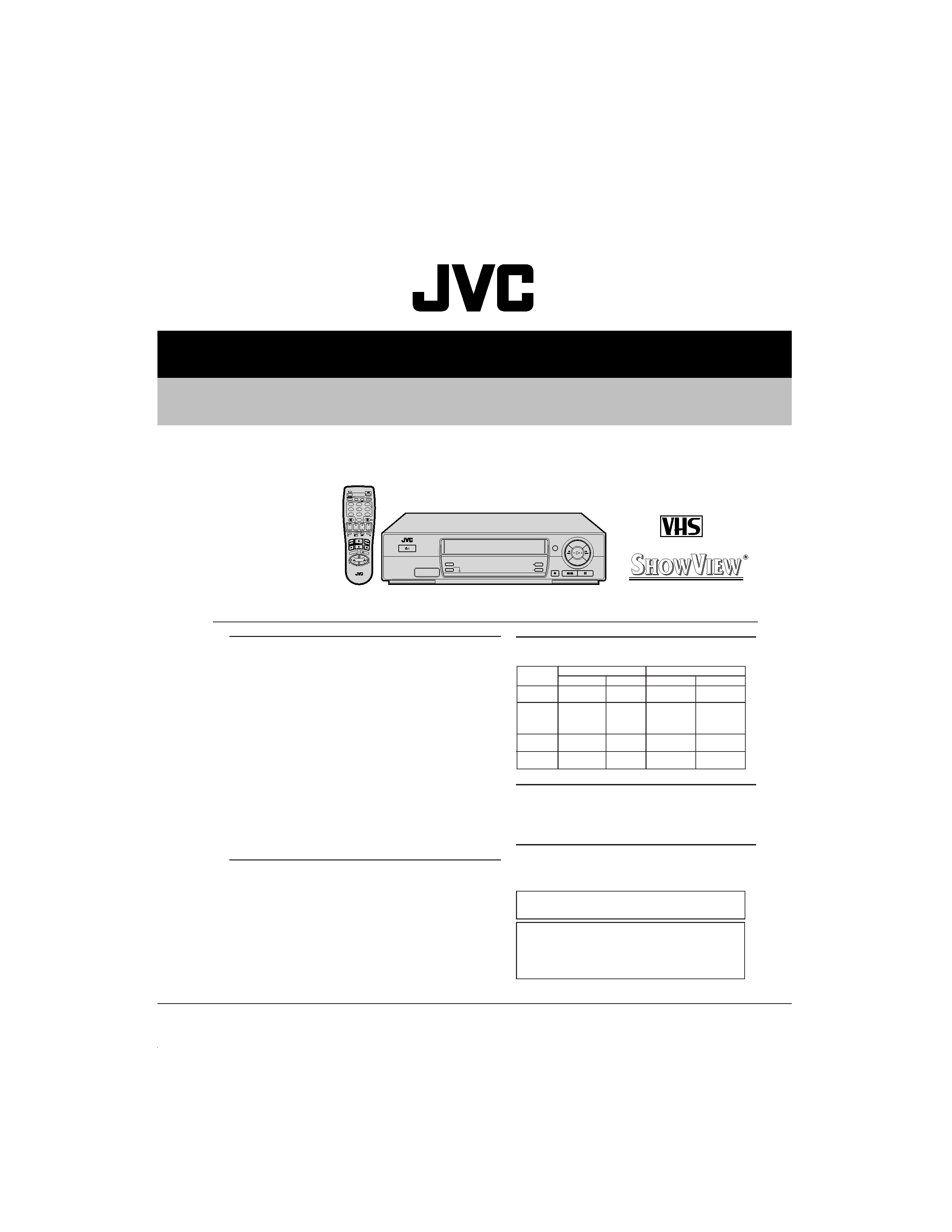
HR-J260MS/J460MS
CARACTERISTIQUES TECHNIQUES
MAGNETOSCOPE
apan
94
(The specifications shown pertain specifically to the models HR-J660MS, HR-J460MS and HR-J260MS.)
PAL SECAM
TV PROG +
TV PROG
T
V
TV
+
TV
0000
START
DEBUT
STOP
FIN
DATE
MEN
U
OK
TV
PROG
TV/VCR
DAILY/QTDN.
VPS/PDC
AUX
?
WEEKLY/HEBDO
PROG
30 SEC
:
AUDIO
123
45
6
7
89
0
2
4
1
3
EXPRESS
MARCHE
SYSTEME COULEUR
AUTO SAT.
CHAINE
AFFICHAGE
GENERALES
Alimentation
: CA 220 240 V`, 50/60 Hz
Consommation
Alimentation en
marche
: 20 W [HR-J660MS]
18 W [HR-J460/260MS]
Alimentation à
l'arrêt
: 5 W
Alimentation en
mode d'économie : 2,8 W
Températures
: 5°C à 40°C (Fonctionnement)
20°C à 60°C (Stockage)
Position de
fonctionnement
: Seulement horizontale
Dimensions (LxHxP)
: 400 x 94 x 275 mm
Poids
: 3,5 kg
Format
: Standard VHS PAL/SECAM
Largeur de bande
: 12,65 mm
Vitesse de bande
(VN)
: 23,39 mm/s
(LD)*
: 11,70 mm/s
Durée maximale
d'enregistrement
(VN)
: 240 mn avec une cassette vidéo E-240
(LD)*
: 480 mn avec une cassette vidéo E-240
* Disponible seulement avec le HR-J660/460MS
VIDEO/AUDIO
Système de signal
: Signaux couleur PAL/SECAM et monochromes CCIR,
625 lignes/50 trames
Système d'enregistrement : Système à deux fois deux têtes rotatives, balayage
hélicoïdal avec combinaison de têtes vidéo DA4 [HR-
J660/460MS]
Système à deux têtes rotatives, balayage hélicoïdal
[HR-J260MS]
Entrée
: 0,5 à 2,0 Vcc, 75 ohms, asymétrique
Sortie
: 1,0 Vcc, 75 ohms, asymétrique
Rapport signal/bruit
: 45 dB
Résolution horizontale : 240 lignes
Gamme de fréquence
: 70 Hz à 10.000 Hz (audio normal)
20 Hz à 20.000 Hz (audio Hi-Fi)
Entrée/sortie
: Prises péritélévision à 21 broches
(ENTREE/SORTIE x 1; ENTREE/DECODEUR x 1)
: Connecteur RCA (SORTIE AUDIO x 1)
[HR-J660MS uniquement]
SYNTONISEUR
Système de syntonisation
: Syntoniseur à synthèse de fréquence
Capacité de canaux TV
: 99 positions (+ position AUX)
Canaux couverts
ATTENTION:
Ce magnétoscope contient des microprocesseurs. Des bruits
électroniques externes ou des interférences peuvent causer un
mauvais fonctionnement. Dans de tels cas, couper l'alimentation et
débrancher le cordon secteur. Puis le rebrancher et remettre
l'alimentation. Sortir la cassette. Après contrôle de la cassette, faire
fonctionner l'appareil comme d'ordinaire.
Les caracteristiques techniques sont pour le mode VN à moins
d'indication contraire.
Présentation et caractéristiques modifiables sans préavis.
MINUTERIE
Référence de l'horloge
: Par quartz
Capacité de
programmation
: Minuterie sur 1 an/8 programmes
Durée de soutien
mémoire
: 60 mn
ACCESSOIRES
Accessoires fournis
: Câble d'antenne,
Boîtier de télécommande à infrarouge,
Pile "R6" x 2,
Câble péritélévision,
Adaptateur antenne
Gamme
SECAM L
PAL B/G
Fréquence
Canaux
Fréquence
Canaux
VHF
49 65
2 4
47 89
E2 E4
(LOW)
MHz
MHz
X, Y, Z
E5 E12
VHF
104 300
5 10
104 300
S1 S20
(HIGH)
MHz
CATV
MHz
M1 M10
U1 U10
Hyper
300 470
CATV
302 470
S21 S41
MHz
MHz
UHF
470 862
21 69
470 862
E21 E69
MHz
MHz

TABLE OF CONTENTS
Section
Title
Page
Section
Title
Page
2.2.25 Upper Drum Assembly .......................................... 2-19
2.3 COMPATIBILITY ADJUSTMENT ................................... 2-20
2.3.1 Checking/Adjustment of FM Waveform Linearity .... 2-20
2.3.2 Checking/Adjustment of the Height and Tilt of the
Audio Control Head .................................................. 2-22
2.3.3 Checking/Adjustment of the Audio Control Head
Phase (X-Value) ......................................................... 2-22
2.3.4 Checking/Adjustment of the Standard Tracking Preset
[HR-J460MS] ................................................................ 2-23
2.3.5 Checking/Adjustment of the Tension Pole ............... 2-23
2.3.6 Adjustment of the Tension Stud ............................... 2-23
2.3.7 Main Brake Torque Adjustment ................................ 2-23
3. ELECTRICAL ADJUSTMENT
3.1 PRECAUTION ................................................................. 3-1
3.1.1 Required test equipment ........................................... 3-1
3.1.2 Required adjustment tools ......................................... 3-1
3.1.3 Colour bar signal,colour bar pattern ........................... 3-1
3.2 SERVO CIRCUIT ............................................................. 3-2
3.2.1 PB switching point ..................................................... 3-2
3.2.2 Slow tracking preset .................................................. 3-2
3.3 VIDEO CIRCUIT .............................................................. 3-3
3.3.1 Auto picture ................................................................ 3-3
3.4 ON SCREEN CIRCUIT ..................................................... 3-3
3.4.1 Character position ...................................................... 3-3
4. CHARTS AND DIAGRAMS
NOTES OF SCHEMATIC DIAGRAM ...................................... 4-1
CIRCUIT BOARD NOTES ....................................................... 4-2
4.1 BOARD INTERCONNECTIONS ...................................... 4-3
4.2 VIDEO/N.AUDIO AND SECAM SCHEMATIC DIAGRAMS . 4-5
4.3 ON SCREEN SCHEMATIC DIAGRAM ............................ 4-7
4.4 SYSTEM CONTROL SCHEMATIC DIAGRAM ................. 4-9
4.5 SWITCHING REGULATOR SCHEMATIC DIAGRAM ..... 4-11
4.6 TUNER SCHEMATIC DIAGRAM ................................... 4-13
4.7 TERMINAL SCHEMATIC DIAGRAM ............................. 4-15
4.8 SW/DISPLAY AND LED SCHEMATIC DIAGRAMS ....... 4-17
4.9 MAIN, A/C HEAD AND LED CIRCUIT BOARDS ........... 4-21
4.10 FDP GRID ASSIGNMENT AND ANODE CONNECTION .. 4-23
4.11 REMOTE CONTROL SCHEMATIC DIAGRAM ........... 4-24
4.12 VOLTAGE CHARTS ..................................................... 4-25
4.13 SYSTEM CONTROL BLOCK DIAGRAM ..................... 4-27
4.14 VIDEO BLOCK DIAGRAM .......................................... 4-29
4.15 AUDIO BLOCK DIAGRAM ......................................... 4-31
5. PARTS LIST
5.1 PACKING AND ACCESSORY ASSEMBLY <M1> .......... 5-1
5.2 CABINET AND CHASSIS ASSEMBLY <M2> ................ 5-2
5.3 MECHANISM ASSEMBLY <M4> .................................. 5-4
5.4 ELECTRICAL PARTS LIST ............................................... 5-6
MAIN BOARD ASSEMBLY <03> ........................................ 5-6
AUDIO CONTROL HEAD BOARD ASSEMBLY <12> ....... 5-12
LOADING MOTOR BOARD ASSEMBLY <55> ................. 5-12
LED BOARD ASSEMBLY <90> ......................................... 5-12
Important Safety Precautions
INSTRUCTIONS
1. DISASSEMBLY
1.1 DISASSEMBLY FLOW CHART ....................................... 1-1
1.2 HOW TO READ THE DISASSEMBLY AND ASSEMBLY . 1-1
1.3 DISASSEMBLY/ASSEMBLY METHOD ........................... 1-1
1.4 SERVICE POSITION ........................................................ 1-4
1.4.1 How to take out the Mechanism and Main board assemblies . 1-4
1.5 MECHANISM SERVICE MODE ...................................... 1-5
1.5.1 How to set the "MECHANISM SERVICE MODE" ...... 1-5
1.6 EMERGENCY DISPLAY FUNCTION ............................... 1-6
1.6.1 How to display record of an emergency faults .......... 1-6
1.6.2 Detail of emergency faults ......................................... 1-6
1.6.3 How to clear emergency record ................................. 1-6
1.7 SYSCON CIRCUIT ........................................................... 1-7
1.7.1 Syscon CPU pin function (IC3001) 1/2 ....................... 1-7
1.7.2 Syscon CPU pin function (IC3001) 2/2 ....................... 1-8
2. MECHANISM ADJUSTMENT
2.1 BEFORE STARTING REPAIR AND ADJUSTMENT .......... 2-1
2.1.1 Precautions ................................................................ 2-1
2.1.2 Checking for Proper Mechanical Operations .............. 2-1
2.1.3 Manually Removing the Cassette Tape ...................... 2-1
2.1.4 Jigs and Tools Required for Adjustment .................... 2-3
2.1.5 Maintenance and Inspection ...................................... 2-3
2.2 REPLACEMENT OF MAJOR PARTS .............................. 2-6
2.2.1 Before Starting Disassembling (Phase matching
between mechanical parts) ........................................ 2-6
2.2.2 How to Set the Mechanism Assembling Mode ......... 2-7
2.2.3 Cassette Holder Assembly ......................................... 2-7
2.2.4 Pinch Roller Arm Assembly ...................................... 2-10
2.2.5 Guide Arm Assembly and Press Lever Assembly .... 2-10
2.2.6 Audio Control Head .................................................. 2-10
2.2.7 Loading Motor .......................................................... 2-11
2.2.8 Capstan Motor ......................................................... 2-11
2.2.9 Pole Base Assembly (supply or take-up side) .......... 2-12
2.2.10 Rotary Encoder ...................................................... 2-12
2.2.11 Clutch Unit ............................................................. 2-13
2.2.12 Change Lever Assembly, Direct Gear and Clutch Gear1 2-13
2.2.13 Link Lever .............................................................. 2-13
2.2.14 Cassette Gear, Control Cam and Worm Gear ........ 2-14
2.2.15 Control Plate .......................................................... 2-14
2.2.16 Loading Arm Gear (supply or take-up side) and
Loading Arm Gear Shaft ........................................ 2-15
2.2.17 Take-up Lever, Take-up Head and Control Plate Guide . 2-16
2.2.18 Capstan Brake Assembly ....................................... 2-17
2.2.19 Sub Brake Assembly (take-up side) ....................... 2-17
2.2.20 Main Brake Assembly (take-up side), Reel Disk
(take-up side) and Main Brake Assembly (supply side) . 2-17
2.2.21 Tension Brake Assembly, Reel Disk (supply side)
and Tension Arm Assembly ................................... 2-18
2.2.22 Idler Lever, Idler Arm Assembly ............................ 2-18
2.2.23 Stator Assembly .................................................... 2-18
2.2.24 Rotor Assembly ..................................................... 2-19
HR-J260MS
HR-J460MS
VIDEO HEAD
2 HEAD
4 HEAD
RECORDING AND PLAYBACK SPEED
SP
SP/LP
SHUTTLE SEARCH
SP : x9
SP/LP : x9
HQ SYSTEM
WC, DE
WC, DE, YNR
AUTO SP/LP TIMER
NOT USED
USED
The following table lists the differing points between Models ( HR-J260MS and HR-J460MS ) in this series.
Important Safety Precautions
Prior to shipment from the factory, JVC products are strictly inspected to conform with the recognized product safety and electrical codes
of the countries in which they are to be sold. However, in order to maintain such compliance, it is equally important to implement the
following precautions when a set is being serviced.
Fig.1
1. Locations requiring special caution are denoted by labels and
inscriptions on the cabinet, chassis and certain parts of the
product. When performing service, be sure to read and com-
ply with these and other cautionary notices appearing in the
operation and service manuals.
2. Parts identified by the
symbol and shaded (
) parts are
critical for safety.
Replace only with specified part numbers.
Note: Parts in this category also include those specified to com-
ply with X-ray emission standards for products using
cathode ray tubes and those specified for compliance
with various regulations regarding spurious radiation
emission.
3. Fuse replacement caution notice.
Caution for continued protection against fire hazard.
Replace only with same type and rated fuse(s) as specified.
4. Use specified internal wiring. Note especially:
1) Wires covered with PVC tubing
2) Double insulated wires
3) High voltage leads
5. Use specified insulating materials for hazardous live parts.
Note especially:
1) Insulation Tape
3) Spacers
5) Barrier
2) PVC tubing
4) Insulation sheets for transistors
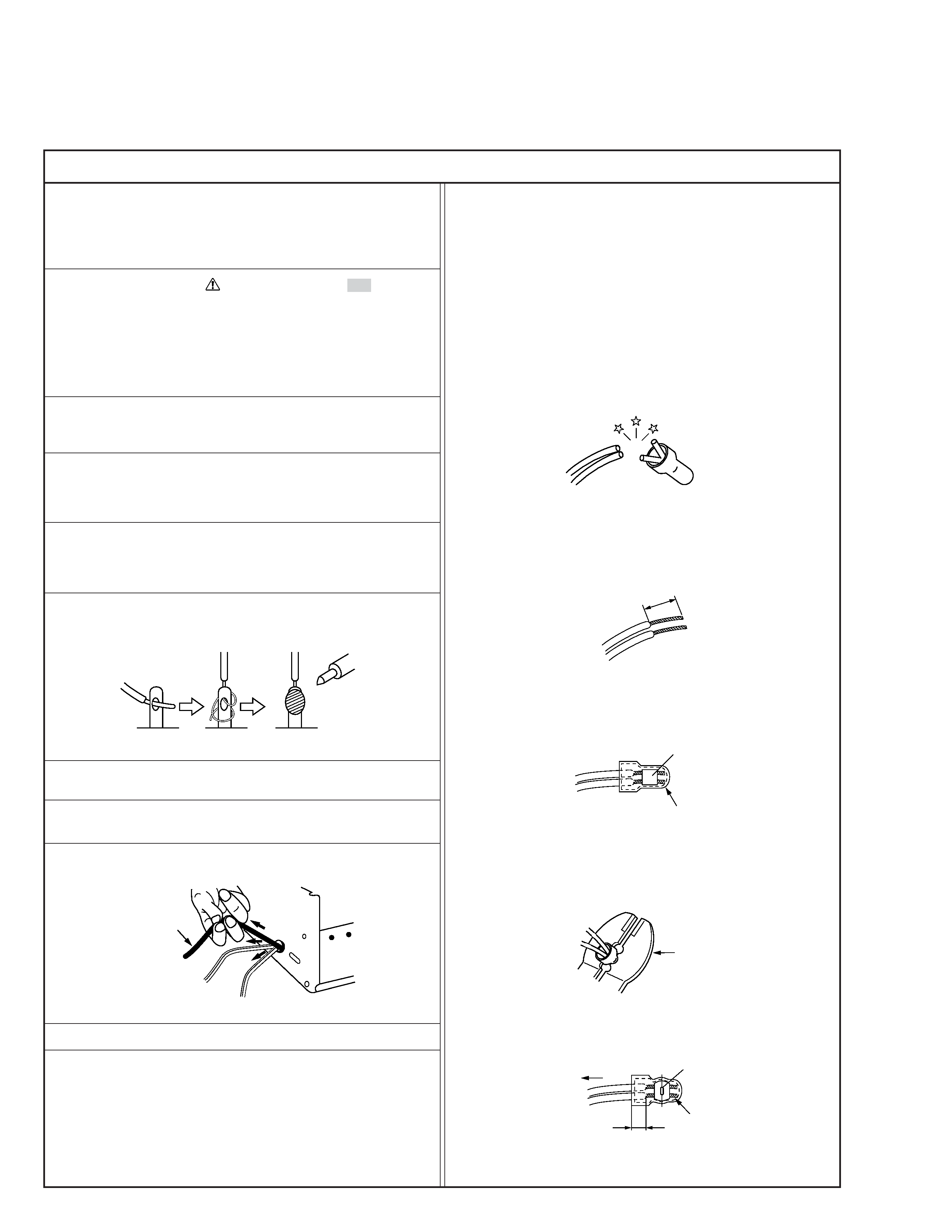
6. When replacing AC primary side components (transformers,
power cords, noise blocking capacitors, etc.) wrap ends of
wires securely about the terminals before soldering.
Power cord
Fig.2
10. Also check areas surrounding repaired locations.
11. Products using cathode ray tubes (CRTs)
In regard to such products, the cathode ray tubes themselves,
the high voltage circuits, and related circuits are specified for
compliance with recognized codes pertaining to X-ray emission.
Consequently, when servicing these products, replace the cath-
ode ray tubes and other parts with only the specified parts.
Under no circumstances attempt to modify these circuits.
Unauthorized modification can increase the high voltage value
and cause X-ray emission from the cathode ray tube.
12. Crimp type wire connector
In such cases as when replacing the power transformer in sets
where the connections between the power cord and power
transformer primary lead wires are performed using crimp type
connectors, if replacing the connectors is unavoidable, in or-
der to prevent safety hazards, perform carefully and precisely
according to the following steps.
1) Connector part number : E03830-001
2) Required tool : Connector crimping tool of the proper type
which will not damage insulated parts.
3) Replacement procedure
(1) Remove the old connector by cutting the wires at a point
close to the connector.
Important : Do not reuse a connector (discard it).
Fig.7
cut close to connector
Fig.3
(2) Strip about 15 mm of the insulation from the ends of
the wires. If the wires are stranded, twist the strands to
avoid frayed conductors.
15 mm
Fig.4
(3) Align the lengths of the wires to be connected. Insert
the wires fully into the connector.
Connector
Metal sleeve
Fig.5
(4) As shown in Fig.6, use the crimping tool to crimp the
metal sleeve at the center position. Be sure to crimp fully
to the complete closure of the tool.
1
Precautions during Servicing
7. Observe that wires do not contact heat producing parts
(heatsinks, oxide metal film resistors, fusible resistors, etc.)
8. Check that replaced wires do not contact sharp edged or
pointed parts.
9. When a power cord has been replaced, check that 10-15 kg of
force in any direction will not loosen it.
1.25
2.0
5.5
Crimping tool
Fig.6
(5) Check the four points noted in Fig.7.
Not easily pulled free
Crimped at approx. center
of metal sleeve
Conductors extended
Wire insulation recessed
more than 4 mm
S40888-01
Safety Check after Servicing
Examine the area surrounding the repaired location for damage or deterioration. Observe that screws, parts and wires have been
returned to original positions, Afterwards, perform the following tests and confirm the specified values in order to verify compli-
ance with safety standards.
1. Insulation resistance test
Confirm the specified insulation resistance or greater between power cord plug prongs and
externally exposed parts of the set (RF terminals, antenna terminals, video and audio input
and output terminals, microphone jacks, earphone jacks, etc.). See table 1 below.
2. Dielectric strength test
Confirm specified dielectric strength or greater between power cord plug prongs and exposed
accessible parts of the set (RF terminals, antenna terminals, video and audio input and output
terminals, microphone jacks, earphone jacks, etc.). See table 1 below.
3. Clearance distance
When replacing primary circuit components, confirm specified clearance distance (d), (d') be-
tween soldered terminals, and between terminals and surrounding metallic parts. See table 1
below.
4. Leakage current test
Confirm specified or lower leakage current between earth ground/power cord plug prongs
and externally exposed accessible parts (RF terminals, antenna terminals, video and audio
input and output terminals, microphone jacks, earphone jacks, etc.).
Measuring Method : (Power ON)
Insert load Z between earth ground/power cord plug prongs and externally exposed accessi-
ble parts. Use an AC voltmeter to measure across both terminals of load Z. See figure 9 and
following table 2.
5. Grounding (Class 1 model only)
Confirm specified or lower grounding impedance between earth pin in AC inlet and externally exposed accessible parts (Video in,
Video out, Audio in, Audio out or Fixing screw etc.).
Measuring Method:
Connect milli ohm meter between earth pin in AC inlet and exposed accessible parts. See figure 10 and grounding specifications.
d'
d
Chassis
Power cord,
primary wire
Region
USA & Canada
Europe & Australia
Grounding Impedance (Z)
Z
0.1 ohm
Z
0.5 ohm
AC inlet
Earth pin
Exposed accessible part
Milli ohm meter
Grounding Specifications
Fig. 10
ab
c
V
Externally
exposed
accessible part
Z
Fig. 9
Fig. 8
Clearance Distance (d), (d')
d, d'
3 mm
d, d'
4 mm
d, d'
3.2 mm
1 M
R 12 M/500 V DC
Dielectric Strength
AC 1 kV 1 minute
AC 1.5 kV 1 miute
AC 1 kV 1 minute
AC Line Voltage
100 V
100 to 240 V
110 to 130 V
110 to 130 V
200 to 240 V
Japan
USA & Canada
Europe & Australia
R
10 M
/500 V DC
Region
Insulation Resistance (R)
R
1 M
/500 V DC
AC 3 kV 1 minute
(Class
2)
AC 1.5 kV 1 minute
(Class
1)
d
4 mm
d'
8 mm (Power cord)
d'
6 mm (Primary wire)
Table 1 Specifications for each region
a, b, c
Leakage Current (i)
AC Line Voltage
100 V
110 to 130 V
110 to 130 V
220 to 240 V
Japan
USA & Canada
i
1 mA rms
Exposed accessible parts
Exposed accessible parts
Antenna earth terminals
Other terminals
i
0.5 mA rms
i
0.7 mA peak
i
2 mA dc
i
0.7 mA peak
i
2 mA dc
Europe & Australia
Region
Load Z
1 k
2 k
1.5 k
0.15
µF
50 k
Table 2 Leakage current specifications for each region
Note: These tables are unofficial and for reference only. Be sure to confirm the precise values for your particular country and locality.
2
S40888-01
1-1
SECTION 1
DISASSEMBLY
1.3 DISASSEMBLY/ASSEMBLY METHOD
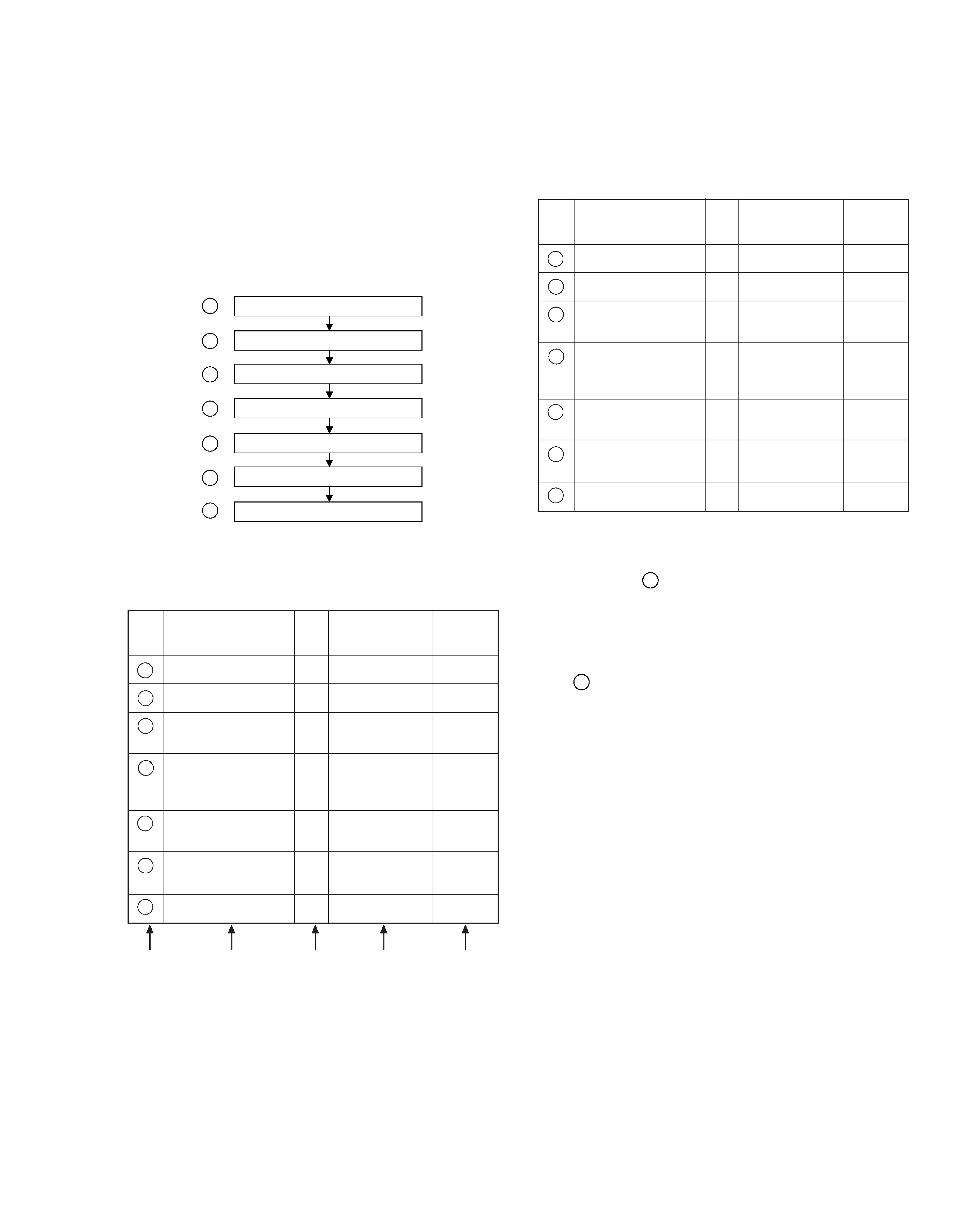
1.1 DISASSEMBLY FLOW CHART
This flowchart lists the disassembling steps for the cabinet
parts and P.C. boards in order to gain access to item(s)
to be serviced. When reassembling, perform the step(s) in
reverse order. Bend, route and dress the flat cables as they
were originally laid.
Top cover
Bracket
Front panel assembly
DRUM assembly
Mechanism assembly
Main board assembly
Bottom cover
1
2
3
4
5
6
7
<NOTE1>
When reattaching the Front panel assembly, make sure that
the door opener
a of the Cassette holder assembly is low-
ered in position prior to the reinstallation.
<NOTE2>
When reattaching the Front panel assembly, pay careful at-
tention to the switch lever not to make it touch the switch
knob
b of the Main board assembly from the side.
(If the switch knob of the Main board assembly is damaged,
cassette loading is impossible.)
<NOTE3>
When inserting the flat wire into the connector, be careful
not to mistake the positioning of its electrodes.
<NOTE4>
· When it is required to remove the screws (S6) retaining
the Mechanism assembly, please refer to the "Procedures
for Lowering the Cassette holder assembly". (See on
pages 1-3.)
· When removing the Mechanism assembly only, unhook
the two spacers connecting it with the Main board as-
sembly with pliers from the back side of the Main board
assembly first, and then remove the Mechanism assem-
bly.
· When reattaching the Mechanism assembly to the Main
board assembly, take care not to damage the sensors on
the Main board. (D3001: LED, Q3002: Start sensor, Q3003:
End sensor)
<NOTE5>
When remove the bottom cover, push down the two tabs
L4 to slide the bottom cover.
1.2 HOW TO READ THE DISASSEMBLY AND ASSEMBLY
(1) Order of steps in Procedure
When reassembling, perform the step(s) in the reverse
order. These numbers are also used as the identification
(location) NO. of parts Figures.
(2) Part name to be removed or installed.
(3) Fig.No. showing procedure or part location
(4) Indentification of part to be removed,unhooked,unlocked,
released,unpluged,unclamped or unsoldered. P = Spring,
W = Washer, S = Screw, L = Locking tab, * = Unhook,unlock,
release,unplug or unsolder.
(5) Adjustment information for installation
(1)
(2)
(3)
(4)
(5)
1
TOP COVER
D1
4(S1), (S2)
2
BRACKET
D2
2(S3)
3
FRONT PANEL
D3
7(L1)
<NOTE 1>
ASSEMBLY
<NOTE 2>
4
DRUM ASSEMBLY
D4
2(S4), 3(S5),
<NOTE 3>
DRUM SHIELD,
WR1,WR2,*CN1
5
MECHANISM
D5
2(S6),2(S7),WR3, <NOTE 3>
ASSEMBLY
2(L2), *CN1
<NOTE 4>
6
MAIN BOARD
D6
3(S8),(S9),(S10),
ASSEMBLY
6(L3)
7
BOTTOM COVER
D7
2(L4), 9(L5)
<NOTE 5>
STEP
/LOC
NO.
PART NAME
FIG.
NO.
POINT
NOTE