COPYRIGHT © 2003 VICTOR COMPANY OF JAPAN, LTD
SERVICE MANUAL
For disassembling and assembling of MECHANISM ASSEMBLY, refer to the SERVICE MANUAL No.86700(MECHANISM ASSEMBLY).
GENERAL
Power requirement : AC 220 V 240 Vd, 50 Hz/60 Hz
Power consumption
Power on
: 42 W
Power off
: 12 W
Temperature
Operating
: 5
°C to 40°C
Storage
: 20
°C to 60°C
Operating position : Horizontal only
Dimensions (WxHxD)
: 435 mm x 98 mm x 357 mm
Weight
: 5.3 kg
Input/Output
: 21-pin SCART connectors:
IN/OUT x 1, IN/DECODER x 1
RCA connectors:
VIDEO IN x 1, AUDIO IN x 1,
AUDIO OUT x 1
S-Video connectors:
IN x 1, OUT x 1
DV connector:
IN/OUT x 1 (4-pin.IEEE1394
conformity, digital input/output)
HDD DECK VIDEO/AUDIO
Video format
: MPEG2 (VBR)
Audio format
: MPEG1 Layer2
Maximum recording time (approx.)
(DV)
: 6 hours
(SP)
: 20 hours
(LP)
: 28 hours
(EP)
: 56 hours
(SEP)
: 80 hours
VHS DECK VIDEO/AUDIO
Signal system
: PAL-type colour signal and CCIR
monochrome signal, 625 lines
50 fields
Recording system : DA4 (Double Azimuth) head helical
scan system
Format
: S-VHS/VHS PAL standard
Signal-to-noise ratio: 45 dB
Horizontal resolution
: 250 lines (VHS)
400 lines (S-VHS)
Frequency range
: 70 Hz to 10,000 Hz (Normal audio)
20 Hz to 20,000 Hz (Hi-Fi audio)
Maximum recording time
(SP)
: 240 min. with E-240 video cassette
(LP)
: 480 min. with E-240 video cassette
TUNER/TIMER
TV channel storage capacity
: 99 positions (+AUX position)
Tuning system
: Frequency synthesized tuner
Channel coverage : VHF 47 MHz 89 MHz/
104 MHz 300 MHz/
302 MHz 470 MHz
UHF 470 MHz 862 MHz
Memory backup time
: Approx. 10 min.
ACCESSORIES
Provided accessories
: RF cable,
21-pin SCART cable,
Satellite Controller,
Infrared remote control unit,
"R6" battery x 2
Specifications shown are for SP mode (VHS) unless otherwise
specified.
E.& O.E. Design and specifications subject to change without
notice.
ATTENTION
This recorder contains microcomputers. External electronic
noise or interference could cause malfunctioning. In such
cases, switch the recorder off and unplug the mains power
cord. Then plug it in again and turn the recorder on. Take out
the cassette. After checking the cassette, operate the unit as
usual.
No.82966
2003/06
HM-HDS4EK, HM-HDS4EX
HM-HDS4EK,HM-HDS4EX D2HS1
HDD & S-VHS VIDEO RECORDER
SPECIFICATIONS (The specifications shown pertain specifically to the model HM-HDS4EX.)

TABLE OF CONTENTS
Section
Title
Page
Section
Title
Page
Important Safety Precautions
INSTRUCTIONS
1. DISASSEMBLY
1.1 Before disassembling ................................................... 1-1
1.1.1 SYSTEM INFORMATION display .......................... 1-1
1.1.2 STANDALONE mode ............................................. 1-1
1.1.3 Jig RCU mode ........................................................ 1-1
1.1.3.1 Setting the Jig RCU mode ................................ 1-1
1.1.3.2 Setting the user RCU mode .............................. 1-1
1.1.3.3 Table of Jig RCU cord ....................................... 1-1
1.1.4 Manually removing the cassette tape ................... 1-2
1.2 Removing the major parts ........................................... 1-3
1.2.1 How to read the procedure table ........................... 1-3
1.2.2 Disassembly procedure ........................................ 1-3
1.3 Emergency display function ........................................ 1-6
1.3.1 Displaying the EMG information ........................... 1-6
1.3.2 Clearing the EMG history ...................................... 1-6
1.3.3 Details of the OSD display in the EMG display mode ... 1-7
1.3.4 EMG content description ....................................... 1-8
1.3.5 EMG detail information<1> ................................... 1-9
1.3.6 EMG detail information<2> ................................. 1-10
1.3.7 EMG detail information<3> ................................. 1-10
1.4 Service position ......................................................... 1-11
1.4.1 How to set the "Service position" ........................ 1-11
1.5 Mechanism service mode ......................................... 1-11
1.5.1 How to set the "Mechanism service mode" ......... 1-11
1.5.2 How to exit from the "Mechanism service mode" 1-11
1.6 Maintenance and inspection ..................................... 1-12
1.6.1 Cleaning .............................................................. 1-12
1.6.2 Lubrication .......................................................... 1-12
1.6.3 Suggested servicing schedule for main components .. 1-12
2. MECHANISM
Refet to the SERVICE MANUAL No.86700 (MECHANISM AS-
SEMBLY)
3. ADJUSTMENT
3.1 Before adjustment ....................................................... 3-1
3.1.1 Precaution .............................................................. 3-1
3.1.2 Required test equipments ..................................... 3-1
3.1.3 Required adjustment tools .................................... 3-1
3.1.4 Color(colour) bar signal, color(colour) bar pattern 3-1
3.1.5 Switch settings ...................................................... 3-1
3.1.6 Manual tracking mode (Auto tracking ON/OFF) setting 3-2
3.1.7 EVR sdjustment ............................................................ 3-2
3.2 Mechanism compatibility adjustment .......................... 3-2
3.2.1 Tension pole position ............................................. 3-2
3.2.2 FM waveform linearity ........................................... 3-3
3.2.3 Height and tilt of the A/C head .............................. 3-3
3.2.4 A/C head phase(X-value) ...................................... 3-4
3.3 Electrical Adjustment ................................................... 3-4
3.3.1 Servo circuit .......................................................... 3-4
3.3.1.1 Switching point ................................................. 3-4
3.3.1.2 Slow tracking preset ......................................... 3-5
3.3.2 Video circuit ........................................................... 3-5
3.3.2.1 EE Y/PB Y(S-VHS/VHS)level ........................... 3-5
3.3.3 Audio circuit ........................................................... 3-5
3.3.3.1 Audio REC FM ................................................. 3-5
3.3.4 Digital circuit ........................................................... 3-6
3.3.4.1 HDD Y level ....................................................... 3-6
3.3.4.2 HDD C level ...................................................... 3-6
3.3.5 Syscon circuit ........................................................ 3-6
3.3.5.1 Timer clock ....................................................... 3-6
4. CHARTS AND DIAGRAMS
4.1 BOARD INTERCONNECTIONS ................................. 4-3
4.2 SW REG SCHEMATIC DIAGRAM ............................... 4-5
4.3 MAIN(VIDEO/N.AUDIO) SCHEMATIC DIAGRAM ....... 4-7
4.4 MAIN(S-SUB) SCHEMATIC DIAGRAM ....................... 4-9
4.5 MAIN(FMA) SCHEMATIC DAIGRAM ........................ 4-11
4.6 MAIN(AUDIO I/O) SCHEMATIC DIAGRAM ............... 4-13
4.7 MAIN(SYSCON) SCHEMATIC DIAGRAM ................. 4-15
4.8 MAIN(TUNER) SCHEMATIC DIAGRAM .................... 4-17
4.9 MAIN(FRONT), S-JACK, ADV.JOG AND LED/SW
SCHEMATIC DIAGRAMS ........................................ 4-19
4.10 MAIN(CONNECTION) SCHEMATIC DIAGRAM ...... 4-21
4.11 2D DIGITAL SCHEMATIC DIAGRAM ...................... 4-23
4.12 TERMINAL(V_IO) SCHEMATIC DIAGRAM ............. 4-25
4.13 TERMINAL(I/O) SCHEMATIC DIAGRAM ................ 4-27
4.14 DEMODULATOR SCHEMATIC DAIGRAM .............. 4-29
4.15 DIGITAL(ASIC IF) SCHEMATIC DIAGRAM ............. 4-31
4.16 DIGITAL(MPEG DEC) SCHEMATIC DIAGRAM ...... 4-33
4.17 DIGITAL(MPEG ENC) SCHEMATIC DIAGRAM ...... 4-35
4.18 DIGITAL(CONNECTION) SCHEMATIC DIAGRAM . 4-37
4.19 DIGITAL(AUDIO AD/DA) SCHEMATIC DIAGRAM .. 4-39
4.20 DIGITAL(DV_CODEC) SCHEMATIC DIAGRAM ..... 4-41
4.21 MAIN(ON SCREEN) SCHEMATIC DIAGRAM ......... 4-43
4.22 MAIN CIRUCIT BOARD ........................................... 4-45
4.23 SW REG & 2D DIGITAL CIRCUIT BOARDS ........... 4-47
4.24 TERMINAL & DEMODULATOR CIRCUIT BOARDS . 4-48
4.25 DIGITAL CIRCUIT BOARD ...................................... 4-49
4.26 S-JACK, ADV.JOG & LED/SW CIRCUIT BOARDS . 4-51
4.27 FDP GRID ASSIGNMENT AND ANODE CONNECTION . 4-52
4.28 VOLTAGE CHARTS ................................................. 4-53
4.29 WAVEFORMS .......................................................... 4-55
4.30 CPU PIN FUNCTION ............................................... 4-56
4.31 SYSTEM CONTROL BLCOK DIAGRAM ................. 4-57
4.32 HDD BLOCK DIAGRAM .......................................... 4-58
4.33 VIDEO BLOCK DIAGRAM ....................................... 4-59
4.34 AUDIO BLOCK DIAGRAM ....................................... 4-63
5. PARTS LIST
5.1 PACKING AND ACCESSORY ASSEMBLY<M1> ........ 5-1
5.2 FINAL ASSEMBLY<M2> ............................................. 5-2
5.3 MECHANISM ASSEMBLY<M4> ................................. 5-4
5.4 ELECTRICAL PARTS LIST ......................................... 5-6
SW.REG BOARD ASSSEMLY<01> ................................. 5-6
MAIN BOARD ASSEMBLY<03> (incl. 2D D,DEMOD) .... 5-7
2D DIGITAL BOARD ASSEMBLY<05> ......................... 5-14
TERMINAL BOARD ASSEMBLY<06> .......................... 5-15
A/C HEAD BOARD ASSEMBLY<12> ........................... 5-17
DEMOD BOARD ASSEMBLY<14> ............................... 5-17
S.JACK BOARD ASSEMBLY<29> ................................ 5-18
ADV.JOG BOARD ASSEMBLY<38> ............................. 5-18
LED/SW BOARD ASSEMBLY<47> ............................... 5-18
DIGITAL BOARD ASSEMBLY<50> ................................ 5-18
LOADING MOTOR BOARD ASSEMBLY<55> .............. 5-23
Important Safety Precautions
Prior to shipment from the factory, JVC products are strictly inspected to conform with the recognized product safety and electrical codes
of the countries in which they are to be sold. However, in order to maintain such compliance, it is equally important to implement the
following precautions when a set is being serviced.
Fig.1
1. Locations requiring special caution are denoted by labels and
inscriptions on the cabinet, chassis and certain parts of the
product. When performing service, be sure to read and com-
ply with these and other cautionary notices appearing in the
operation and service manuals.
2. Parts identified by the
symbol and shaded (
) parts are
critical for safety.
Replace only with specified part numbers.
Note: Parts in this category also include those specified to com-
ply with X-ray emission standards for products using
cathode ray tubes and those specified for compliance
with various regulations regarding spurious radiation
emission.
3. Fuse replacement caution notice.
Caution for continued protection against fire hazard.
Replace only with same type and rated fuse(s) as specified.
4. Use specified internal wiring. Note especially:
1) Wires covered with PVC tubing
2) Double insulated wires
3) High voltage leads
5. Use specified insulating materials for hazardous live parts.
Note especially:
1) Insulation Tape
3) Spacers
5) Barrier
2) PVC tubing
4) Insulation sheets for transistors
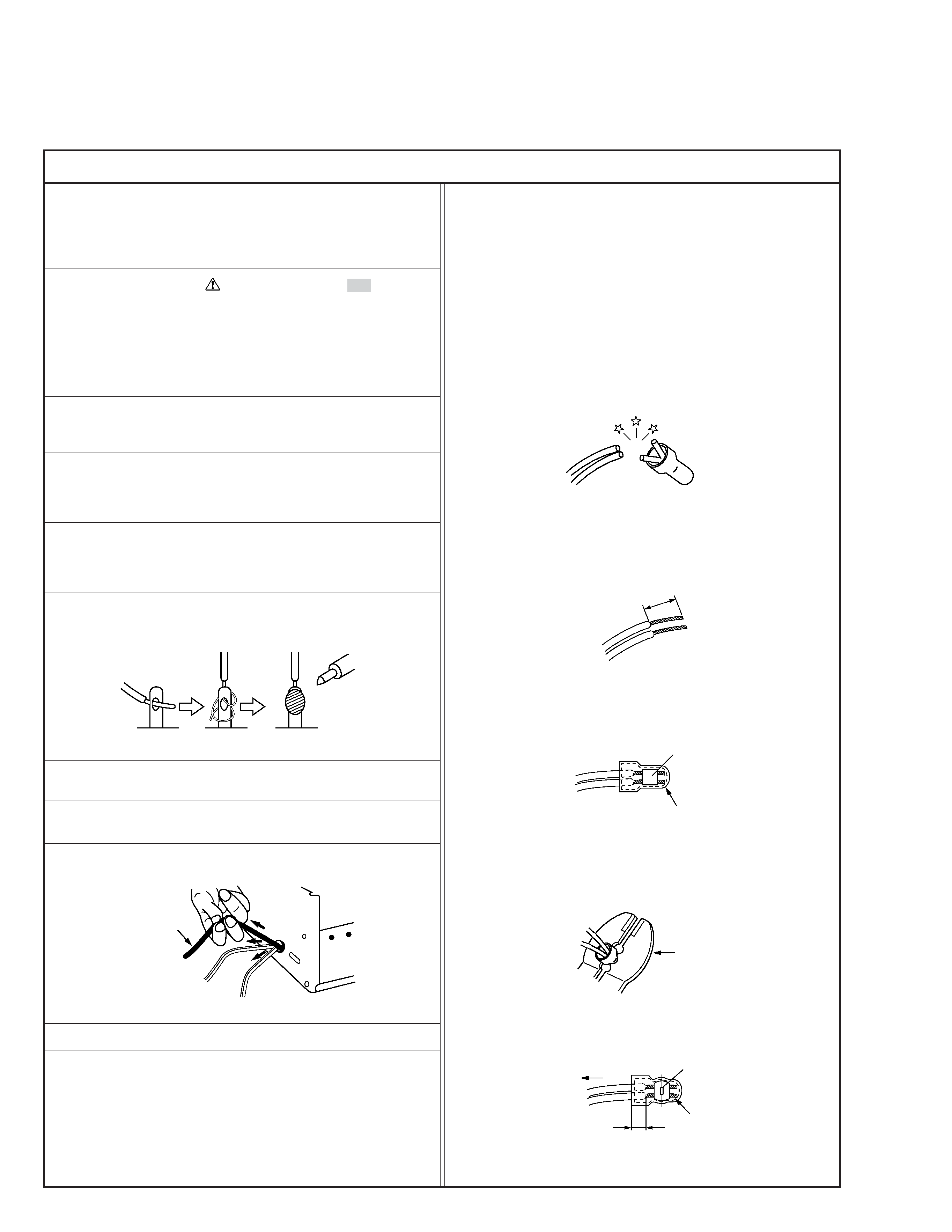
6. When replacing AC primary side components (transformers,
power cords, noise blocking capacitors, etc.) wrap ends of
wires securely about the terminals before soldering.
Power cord
Fig.2
10. Also check areas surrounding repaired locations.
11. Products using cathode ray tubes (CRTs)
In regard to such products, the cathode ray tubes themselves,
the high voltage circuits, and related circuits are specified for
compliance with recognized codes pertaining to X-ray emission.
Consequently, when servicing these products, replace the cath-
ode ray tubes and other parts with only the specified parts.
Under no circumstances attempt to modify these circuits.
Unauthorized modification can increase the high voltage value
and cause X-ray emission from the cathode ray tube.
12. Crimp type wire connector
In such cases as when replacing the power transformer in sets
where the connections between the power cord and power
transformer primary lead wires are performed using crimp type
connectors, if replacing the connectors is unavoidable, in or-
der to prevent safety hazards, perform carefully and precisely
according to the following steps.
1) Connector part number : E03830-001
2) Required tool : Connector crimping tool of the proper type
which will not damage insulated parts.
3) Replacement procedure
(1) Remove the old connector by cutting the wires at a point
close to the connector.
Important : Do not reuse a connector (discard it).
Fig.7
cut close to connector
Fig.3
(2) Strip about 15 mm of the insulation from the ends of
the wires. If the wires are stranded, twist the strands to
avoid frayed conductors.
15 mm
Fig.4
(3) Align the lengths of the wires to be connected. Insert
the wires fully into the connector.
Connector
Metal sleeve
Fig.5
(4) As shown in Fig.6, use the crimping tool to crimp the
metal sleeve at the center position. Be sure to crimp fully
to the complete closure of the tool.
1
Precautions during Servicing
7. Observe that wires do not contact heat producing parts
(heatsinks, oxide metal film resistors, fusible resistors, etc.)
8. Check that replaced wires do not contact sharp edged or
pointed parts.
9. When a power cord has been replaced, check that 10-15 kg of
force in any direction will not loosen it.
1.25
2.0
5.5
Crimping tool
Fig.6
(5) Check the four points noted in Fig.7.
Not easily pulled free
Crimped at approx. center
of metal sleeve
Conductors extended
Wire insulation recessed
more than 4 mm
S40888-01
Safety Check after Servicing
Examine the area surrounding the repaired location for damage or deterioration. Observe that screws, parts and wires have been
returned to original positions, Afterwards, perform the following tests and confirm the specified values in order to verify compli-
ance with safety standards.
1. Insulation resistance test
Confirm the specified insulation resistance or greater between power cord plug prongs and
externally exposed parts of the set (RF terminals, antenna terminals, video and audio input
and output terminals, microphone jacks, earphone jacks, etc.). See table 1 below.
2. Dielectric strength test
Confirm specified dielectric strength or greater between power cord plug prongs and exposed
accessible parts of the set (RF terminals, antenna terminals, video and audio input and output
terminals, microphone jacks, earphone jacks, etc.). See table 1 below.
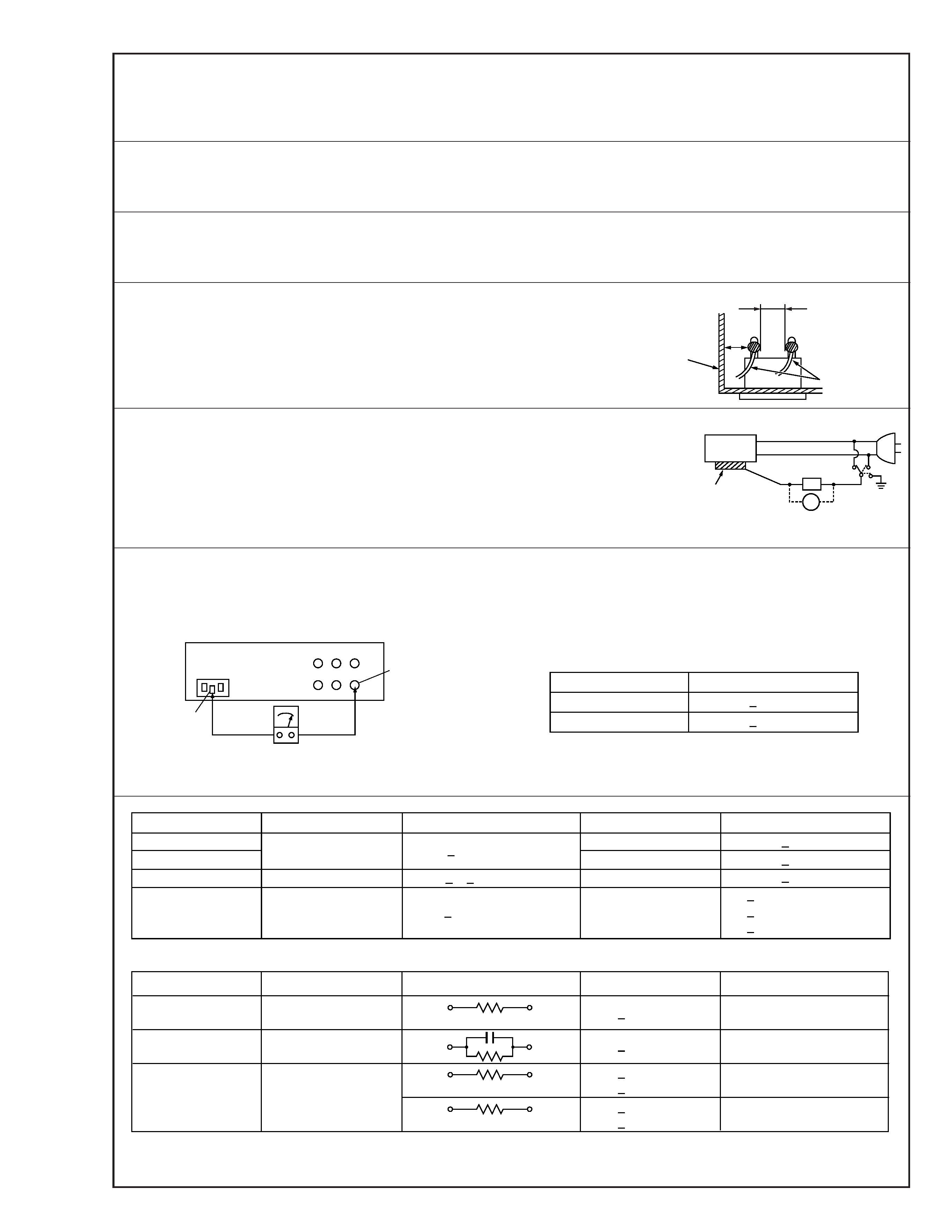
3. Clearance distance
When replacing primary circuit components, confirm specified clearance distance (d), (d') be-
tween soldered terminals, and between terminals and surrounding metallic parts. See table 1
below.
4. Leakage current test
Confirm specified or lower leakage current between earth ground/power cord plug prongs
and externally exposed accessible parts (RF terminals, antenna terminals, video and audio
input and output terminals, microphone jacks, earphone jacks, etc.).
Measuring Method : (Power ON)
Insert load Z between earth ground/power cord plug prongs and externally exposed accessi-
ble parts. Use an AC voltmeter to measure across both terminals of load Z. See figure 9 and
following table 2.
5. Grounding (Class 1 model only)
Confirm specified or lower grounding impedance between earth pin in AC inlet and externally exposed accessible parts (Video in,
Video out, Audio in, Audio out or Fixing screw etc.).
Measuring Method:
Connect milli ohm meter between earth pin in AC inlet and exposed accessible parts. See figure 10 and grounding specifications.
d'
d
Chassis
Power cord,
primary wire
Region
USA & Canada
Europe & Australia
Grounding Impedance (Z)
Z
0.1 ohm
Z
0.5 ohm
AC inlet
Earth pin
Exposed accessible part
Milli ohm meter
Grounding Specifications
Fig. 10
ab
c
V
Externally
exposed
accessible part
Z
Fig. 9
Fig. 8
Clearance Distance (d), (d')
d, d'
3 mm
d, d'
4 mm
d, d'
3.2 mm
1 M
R 12 M/500 V DC
Dielectric Strength
AC 1 kV 1 minute
AC 1.5 kV 1 miute
AC 1 kV 1 minute
AC Line Voltage
100 V
100 to 240 V
110 to 130 V
110 to 130 V
200 to 240 V
Japan
USA & Canada
Europe & Australia
R
10 M
/500 V DC
Region
Insulation Resistance (R)
R
1 M
/500 V DC
AC 3 kV 1 minute
(Class
2)
AC 1.5 kV 1 minute
(Class
1)
d
4 mm
d'
8 mm (Power cord)
d'
6 mm (Primary wire)
Table 1 Specifications for each region
a, b, c
Leakage Current (i)
AC Line Voltage
100 V
110 to 130 V
110 to 130 V
220 to 240 V
Japan
USA & Canada
i
1 mA rms
Exposed accessible parts
Exposed accessible parts
Antenna earth terminals
Other terminals
i
0.5 mA rms
i
0.7 mA peak
i
2 mA dc
i
0.7 mA peak
i
2 mA dc
Europe & Australia
Region
Load Z
1 k
2 k
1.5 k
0.15
µF
50 k
Table 2 Leakage current specifications for each region
Note: These tables are unofficial and for reference only. Be sure to confirm the precise values for your particular country and locality.
2
S40888-01
Hard Disk Drive (HDD)
1. Hard Disk Drive (HDD) Handling Precautions
The HDD is a precision device for use in reading and writing a large amount of data on or from a disk rotating at
a high speed. If it is not handled carefully, either abnormal operation may result or it may not be possible to read
data. The HDD is sensitive to the following items and special care is required in safeguarding against them when
handling an HDD. Also take care in handling a set incorporating an HDD.
1. Vibrations and impacts
2. Static electricity
3. Rough handling
1.1
Handling in transport, etc.
s Be sure to place the HDD in the manufacturer's specified package
carton before transport.
s When receiving a package containing an HDD, check that the pack-
age carton is not damaged (such as having holes in the carton,
crushed corners, etc.).
s Do not impact the packaging carton when loading or unloading it.
s It is not permitted to use the inner package carton only for transport-
ing an HDD.
s Do not stack package cartons one upon another.
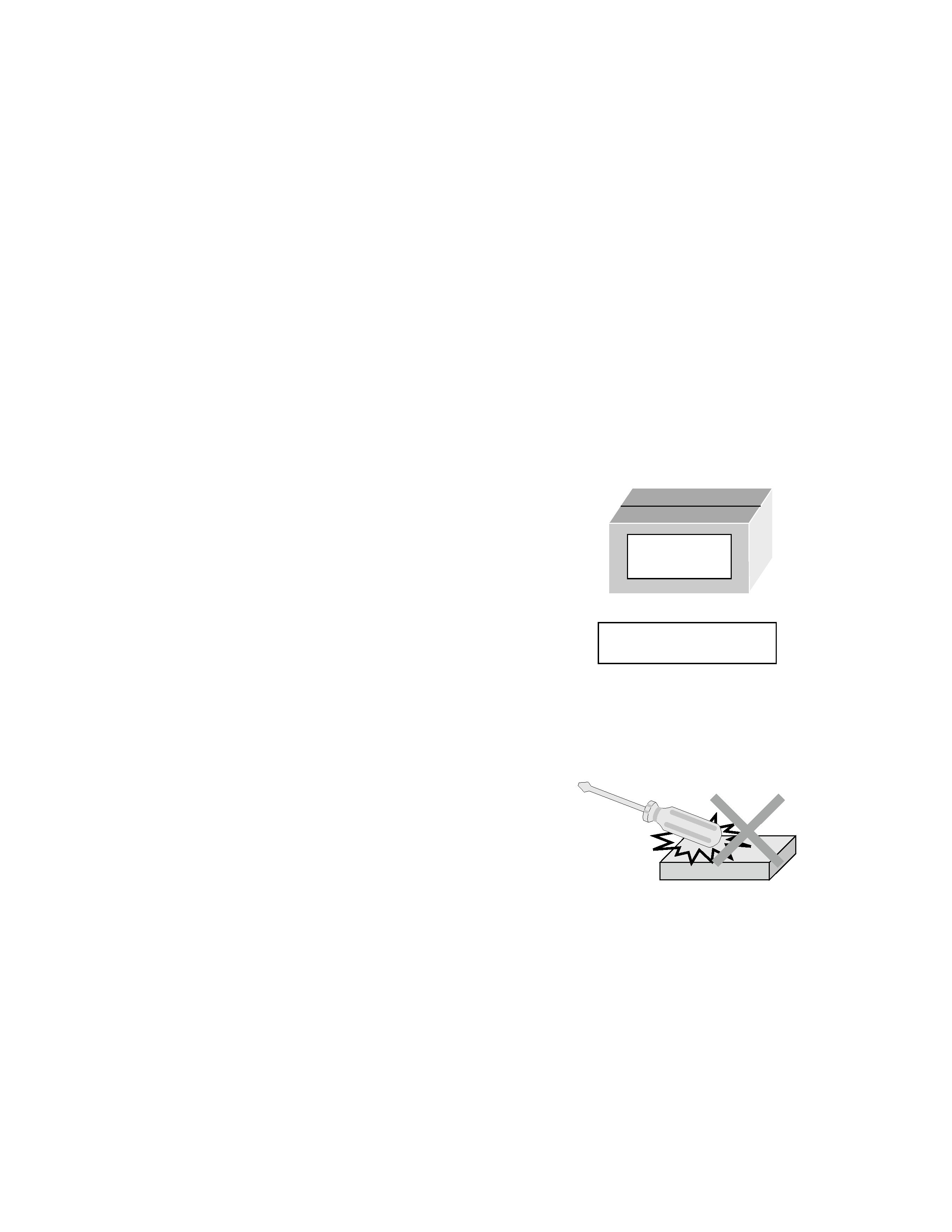
1.2
Handling an HDD in the stand-alone status
s When handling an HDD on a hard workbench, place an antistatic
mat (rubber sheet) or similar object on the hard surface (to prevent
any impacts occurring between the HDD and bench).
s Do not stack the HDDs one upon another.
s Do not knock an HDD with a hard object (such as a screwdriver).
s Do not place an HDD on its side panel without using a support (do
not place an HDD in an unstable position).
1.3
Handling the installation of an HDD
s Place antistatic mats or similar sheets on all of the surfaces on which work is conducted or when the HDD
is transported.
s Do not permit the HDD to knock against the set's brackets.
s When screwing the brackets, be careful not to knock the HDD. When using a power screwdriver, use a low-
shock model and arrange the tightening torque properly.
s When mounting an HDD in a HDD/VHS DUAL RECORDER, take care not to apply excessive force to the
brackets.
HDD
Do not throw or
drop packages.
Be sure to package and
transport the HDDs correctly.