SERVICE MANUAL
No. 82887
July 2001
HM-HDS1EK/EU
SPECIFICATIONS (The specifications shown pertain specifically to the model HM-HDS1EU)
HDD & S-VHS VIDEO RECORDER
Printed in Japan
This service manual is printed on 100% recycled paper.
COPYRIGHT © 2001 VICTOR COMPANY OF JAPAN, LTD.
HM-HDS1EK/EU
No.
82887
VICTOR COMPANY OF JAPAN, LIMITED
VIDEO DIVISION
S40894
F - 1
12
3
4
56
78
9
0
2
1
4
3
>
<
ñ
+
GENERAL
Power requirement
: AC 220 V 240 V ` , 50 Hz/60 Hz
Power consumption
Power on
: 41 W
Power off
: 16 W
Temperature
Operating
: 5°C to 40°C
Storage
: 20°C to 60°C
Operating position
: Horizontal only
Dimensions (WxHxD) : 435 mm x 124 mm x 385 mm
Weight
: 7.3 kg
Input/Output
: 21-pin SCART connectors:
IN/OUT x 1, IN/DECODER x 1
RCA connectors:
VIDEO IN x 1, AUDIO IN x 1,
AUDIO OUT x 1
S-Video connectors: IN x 1, OUT x 1
HDD DECK VIDEO/AUDIO
Video format
: MPEG2 (VBR)
Audio format
: MPEG1 Layer2
Maximum recording time (approx.)
(SP)
: 14 hours
(LP)
: 20 hours
(EP)
: 28 hours
(SEP)
: 40 hours
VHS DECK VIDEO/AUDIO
Signal system
: PAL-type colour signal and CCIR monochrome
signal, 625 lines 50 fields
Recording system
: DA4 (Double Azimuth) head helical scan system
Format
: S-VHS/VHS PAL standard
Signal-to-noise ratio
: 45 dB
Horizontal resolution
(SP/LP)
: 250 lines (VHS)
400 lines (S-VHS)
(EP)
: 220 lines (VHS)
350 lines (S-VHS)
Frequency range
: 70 Hz to 10,000 Hz (Normal audio)
20 Hz to 20,000 Hz (Hi-Fi audio)
Maximum recording time
(SP)
: 240 min. with E-240 video cassette
(LP)
: 480 min. with E-240 video cassette
(EP)
: 720 min. with E-240 video cassette
TUNER/TIMER
TV channel storage capacity
: 99 positions (+AUX position)
Tuning system
: Frequency synthesized tuner
Channel coverage
: VHF 47 MHz 89 MHz/
104 MHz 300 MHz/
302 MHz 470 MHz
UHF 470 MHz 862 MHz
Aerial output
: UHF channels 22 69 (Adjustable)
Memory backup time
: Approx. 60 min.
ACCESSORIES
Provided accessories
: RF cable,
21-pin SCART cable,
Satellite Controller,
Infrared remote control unit,
"R6" battery x 2
Specifications shown are for SP mode unless otherwise specified.
E. & O.E. Design and specifications subject to change without notice.
1
Hard Disk Drive (HDD)
1. Hard Disk Drive (HDD) Handling Precautions
The HDD is a precision device for use in reading and writing a large amount of data on or from a disk rotating at
a high speed. If it is not handled carefully, either abnormal operation may result or it may not be possible to read
data. The HDD is sensitive to the following items and special care is required in safeguarding against them when
handling an HDD. Also take care in handling a set incorporating an HDD.
1. Vibrations and impacts
2. Static electricity
3. Rough handling
1.1
Handling in transport, etc.
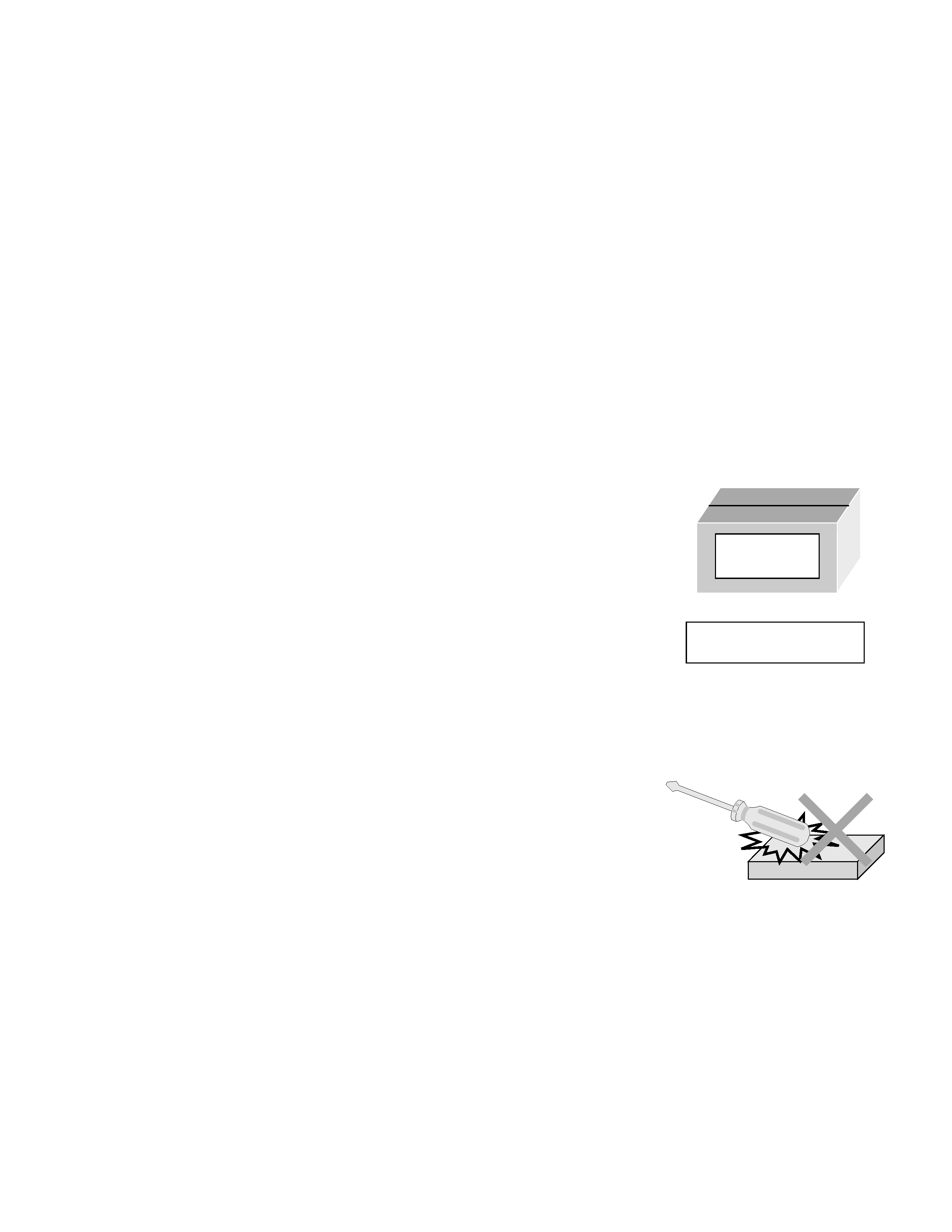
s Be sure to place the HDD in the manufacturer's specified package
carton before transport.
s When receiving a package containing an HDD, check that the pack-
age carton is not damaged (such as having holes in the carton,
crushed corners, etc.).
s Do not impact the packaging carton when loading or unloading it.
s It is not permitted to use the inner package carton only for transport-
ing an HDD.
s Do not stack package cartons one upon another.
1.2
Handling an HDD in the stand-alone status
s When handling an HDD on a hard workbench, place an antistatic
mat (rubber sheet) or similar object on the hard surface (to prevent
any impacts occurring between the HDD and bench).
s Do not stack the HDDs one upon another.
s Do not knock an HDD with a hard object (such as a screwdriver).
s Do not place an HDD on its side panel without using a support (do
not place an HDD in an unstable position).
1.3
Handling the installation of an HDD
s Place antistatic mats or similar sheets on all of the surfaces on which work is conducted or when the HDD
is transported.
s Do not permit the HDD to knock against the set's brackets.
s When screwing the brackets, be careful not to knock the HDD. When using a power screwdriver, use a low-
shock model and arrange the tightening torque properly.
s When mounting an HDD in a HDD/VHS DUAL RECORDER, take care not to apply excessive force to the
brackets.
HDD
Do not throw or
drop packages.
Be sure to package and
transport the HDDs correctly.
2
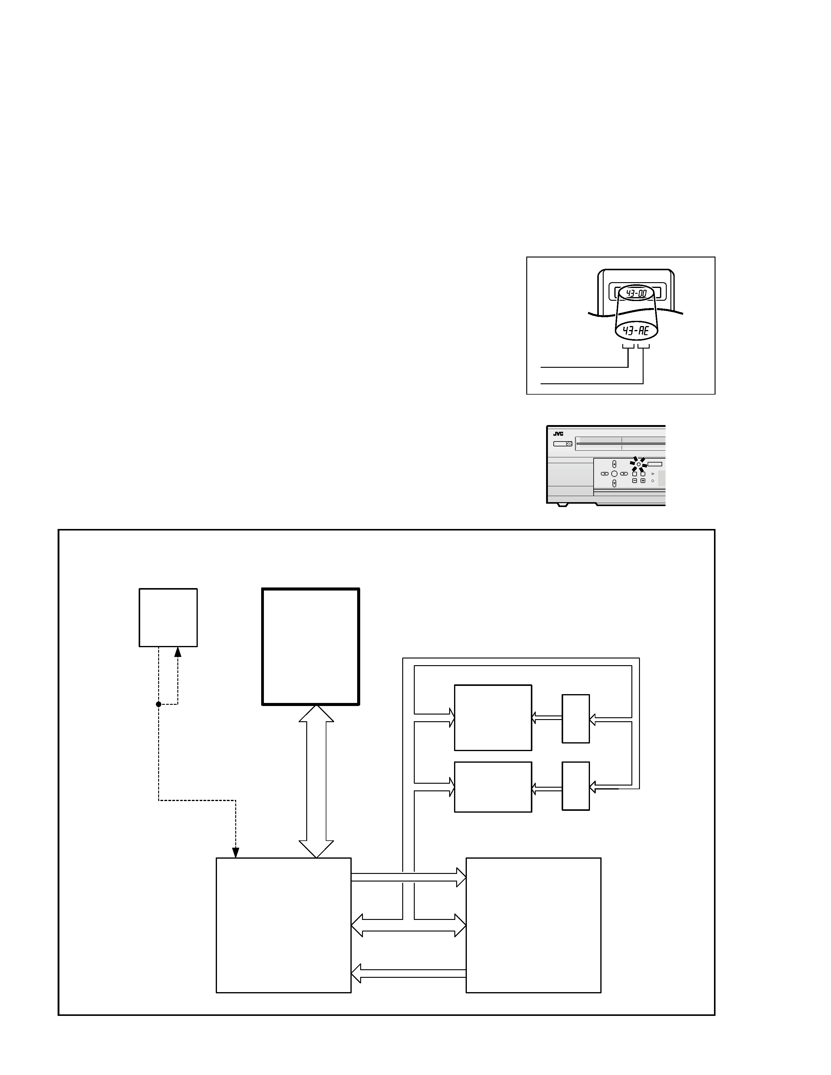
2. In Case of an HDD Failure
When a HDD/VHS DUAL RECORDER AC cord is plugged into a power outlet, the boot loader is read from the
IC8204 (8M FLASH ROM), which activates the HDD and reads the system files in the HDD before getting ready
for operation. In consequence, the HDD/VHS DUAL RECORDER cannot be turned on if the HDD fails.
In case a failure of the HDD is in doubt, use the following procedure to switch the main power of the set ON using
the VHS section alone, by bypassing the HDD operation check.
(1) With the HDD/VHS DUAL RECORDER in the remote control
standby status, transmit code AE from the remote jig for more
than 2 seconds.
(2) The REC LINK button on the HDD/VHS DUAL RECORDER
blinks, indicating that the power supply can be switched ON.
(3) When the code AE is transmitted again from the remote jig,
the button stops blinking and its function is canceled.
Initial mode
Data code
Custom code
43: A code
52: B code
6F: C code
7F: D code
HDD
OK
HM-HDS1
POWER
BS DIGIATL
CHANNEL
Blinks.
ASIC_IF
MPEG_DEC
40GB
HDD
IC8201
IC8001
8M FLASH
OPEN
IC8204
IC8205
IC8206
IC8207
DVD 0_:7_
VIO 0:7
IDE 40PIN
AD 0:31
AD 4:11
AD 12:19
LADO
4:11
LADO
12:19
AD 0:15
AD 16:31
AD 4:19
VHS
SYSCON
HOSTD
A
T
A
KB
US_IN
KB
US_OUT
Address
Latch
Address
Latch
E:08 is displayed in the
case of a
communication error
with the VHS SYSCON
Firmware
HDD driver
Navigation information
boot loader
VHS Navi
back up
<Reference>

Hard Disk Drive (HDD)
Important Safety Precautions
INSTRUCTIONS
1. DISASSEMBLY
1.1 HOW TO REMOVE THE MAJOR PARTS ..................................................... 1-1
1.1.1 Introduction .................................................................................... 1-1
1.2 HOW TO READ THE DISASSEMBLY AND ASSEMBLY .............................. 1-1
1.3 DISCONNECTION OF CONNECTORS (WIRES) ........................................ 1-1
1.4 SCREWS USED CABINET COMPONENTS AND BOARD ASSEMBLIES .. 1-1
1.5 HOW TO REMOVE THE MAJOR PARTS <COM section> ........................... 1-2
1.5.1 Disassembly flow chart .................................................................. 1-2
1.5.2 Disassembly/assembly method <COM section> ............................ 1-2
1.6 HOW TO REMOVE THE MAJOR PARTS <VHS section> ............................ 1-4
1.6.1 Disassembly flow chart .................................................................. 1-4
1.6.2 DIsassembly/assembly method <VHS section> ............................ 1-4
Hard Disk Drive (HDD) Handling Precautions ...................................................... 1-6
1.7 HOW TO REMOVE THE MAJOR PARTS <HDD section> ............................ 1-6
1.7.1 Disassembly flow chart .................................................................. 1-6
1.7.2 DIsassembly/assembly method <HDD section> ............................ 1-6
1.8 SERVICE POSITIONS .................................................................................. 1-7
1.8.1 Service position <VHS SIDE> ........................................................ 1-7
1.8.2 Service position <HDD SIDE> ....................................................... 1-8
1.9 MECHANISM SERVICE MODE .................................................................... 1-9
1.9.1 How to set the "MECHANISM SERVICE MODE" .......................... 1-9
1.10 CONNECTION ........................................................................................... 1-10
1.11 EMERGENCY DISPLAY FUNCTION ........................................................ 1-12
1.11.1 Displaying the emergency information ................................................. 1-12
1.11.2 Clearing the emergency history ........................................................... 1-12
1.11.3 Emergency content description ............................................................ 1-13
1.11.4 Emergency detail information 1 ......................................................... 1-14
1.11.5 Emergency detail information 2 ......................................................... 1-15
2. MECHANISM ADJUSTMENT (VHS)
2.1 Before starting repair and adjustment ............................................................ 2-1
2.1.1 Precautions .................................................................................... 2-1
2.1.2 Checking for proper mechanical operations ................................... 2-1
2.1.3 Manually removing the cassette tape ............................................. 2-1
2.1.4 Jigs and tools required for adjustment ........................................... 2-2
2.1.5 Maintenance and inspection .......................................................... 2-3
2.2 Replacement of major parts .......................................................................... 2-6
2.2.1 Before starting disassembling (Phase matching between mechanical parts) .. 2-6
2.2.2 How to set the "Mechanism assembling mode" ............................. 2-6
2.2.3 Cassette holder assembly .............................................................. 2-6
2.2.4 Pinch roller arm assembly .............................................................. 2-8
2.2.5 Guide arm assembly and press lever assembly ............................. 2-8
2.2.6 A/C head ........................................................................................ 2-8
2.2.7 Loading motor ................................................................................ 2-8
2.2.8 Capstan motor ................................................................................ 2-9
2.2.9 Pole base assembly (supply or take-up side) ................................. 2-9
2.2.10 Rotary encoder ............................................................................ 2-10
2.2.11 Clutch unit .................................................................................... 2-10
2.2.12 Change lever assembly, direct gear, clutch gear and coupling gear . 2-10
2.2.13 Link lever ...................................................................................... 2-11
2.2.14 Cassette gear, control cam and worm gear ................................. 2-11
2.2.15 Control plate ................................................................................. 2-11
2.2.16 Loading arm gear (supply or take-up side) and loading arm gear shaft .. 2-12
2.2.17 Take-up lever, take-up head and control plate guide .................... 2-13
2.2.18 Capstan brake assembly .............................................................. 2-13
2.2.19 Sub brake assembly (take-up side) .............................................. 2-13
2.2.20 Main brake assembly (take-up side), reel disk (take-up side) and
main brake assembly (supply side) .............................................. 2-13
2.2.21 Tension brake assembly, reel disk (supply side) and tension arm assembly . 2-14
2.2.22 Idler lever, idler arm assembly ..................................................... 2-14
2.2.23 Stator assembly ........................................................................... 2-14
2.2.24 Rotor assembly ............................................................................ 2-14
2.2.25 Upper drum assembly .................................................................. 2-15
2.3 Compatibility adjustment ............................................................................. 2-16
2.3.1 FM waveform linearity .................................................................. 2-16
2.3.2 Height and tilt of the A/C head ..................................................... 2-17
2.3.3 A/C head phase (X-value) ............................................................ 2-17
2.3.4 Standard tracking preset .............................................................. 2-18
2.3.5 Tension pole position .................................................................... 2-18
3. ELECTRICAL ADJUSTMENT (VHS)
3.1 PRECAUTION ............................................................................................... 3-1
3.1.1 Required test equipments .............................................................. 3-1
3.1.2 Required adjustment tools ............................................................. 3-1
3.1.3 Color (colour) bar signal,Color (colour) bar pattern ....................... 3-1
3.1.4 Switch settings and standard precautions ...................................... 3-1
3.1.5 EVR Adjustment ............................................................................. 3-1
TABLE OF CONTENTS
Section
Title
Page
Section
Title
Page
3.2 SERVO CIRCUIT .......................................................................................... 3-2
3.2.1 Switching point ............................................................................... 3-2
3.2.2 Slow tracking preset ....................................................................... 3-2
3.3 VIDEO CIRCUIT ........................................................................................... 3-2
3.3.1 D/A level ......................................................................................... 3-2
3.3.2 EE Y level ....................................................................................... 3-3
3.3.3 PB Y level (S-VHS / VHS) .............................................................. 3-3
3.3.4 REC color (colour) level ................................................................. 3-3
3.3.5 Video EQ (Frequency response) .................................................... 3-4
3.3.6 AUTO PICTURE initial setting ........................................................ 3-4
3.4 DIGITAL CIRCUIT ......................................................................................... 3-4
3.4.1 HDD EE Y level .............................................................................. 3-4
3.4.2 HDD PB Y level .............................................................................. 3-5
3.4.3 HDD PB C burst level ..................................................................... 3-5
3.5 AUDIO CIRCUIT ........................................................................................... 3-5
3.5.1 Audio REC FM ............................................................................... 3-5
3.6 SYSCON CIRCUIT [HM-HDS1EU] ............................................................... 3-6
3.6.1 Timer clock ..................................................................................... 3-6
4. CHARTS AND DIAGRAMS
NOTES OF SCHEMATIC DIAGRAM ................................................................... 4-1
CIRCUIT BOARD NOTES .................................................................................... 4-2
4.1 BOARD INTERCONNECTIONS ................................................................... 4-3
4.2 SWITCHING REGULATOR AND REGULATOR SCHEMATIC DIAGRAMS ........... 4-5
4.3 VIDEO/AUDIO SCHEMATIC DIAGRAM ....................................................... 4-7
4.4 SYSTEM CONTROL SCHEMATIC DIAGRAM ............................................. 4-9
4.5 VIDEO I/O SWITCH SCHEMATIC DIAGRAM ............................................ 4-13
4.6 AUDIO I/O SCHEMATIC DIAGRAM ............................................................ 4-15
4.7 CONNECTION SCHEMATIC DIAGRAM .................................................... 4-17
4.8 TUNER SCHEMATIC DIAGRAM ................................................................ 4-19
4.9 3D DIGITAL/2M SCHEMATIC DIAGRAM ................................................... 4-21
4.10 TERMINAL SCHEMATIC DIAGRAM ........................................................ 4-23
4.11 DEMODULATOR SCHEMATIC DIAGRAM ............................................... 4-25
4.12 S-SUB SCHEMATIC DIAGRAM ............................................................... 4-27
4.13 ON SCREEN SCHEMATIC DIAGRAM ..................................................... 4-29
4.14 EJECT SW, DISPLAY, JACK, LED/SW AND LED SCHEMATIC DIAGRAMS .. 4-31
4.15 DIGITAL P.SUP SCHEMATIC DIAGRAM .................................................. 4-33
4.16 DIGITAL VIDEO SCHEMATIC DIAGRAM ................................................. 4-35
4.17 DIGITAL AUDIO SCHEMATIC DIAGRAM ................................................ 4-37
4.18 DIGITAL MPEG DEC SCHEMATIC DIAGRAM ......................................... 4-39
4.19 DIGITAL MPEG ENC SCHEMATIC DIAGRAM ......................................... 4-41
4.20 DIGITAL ASIC IF SCHEMATIC DIAGRAM ............................................... 4-43
4.21 SWITCHING REGULATOR AND REGULATOR CIRCUIT BOARDS ....... 4-45
4.22 3D DIGITAL/2M AND S-SUB CIRCUIT BOARDS .................................... 4-47
4.23 TERMINAL CIRCUIT BOARD .................................................................. 4-48
4.24 EJECT SW, DISPLAY, JACK, LED/SW, AND LED CIRCUIT BOARDS .... 4-49
4.25 MAIN CIRCUIT BOARD ........................................................................... 4-51
4.26 DEMODULATOR AND ON SCREEN CIRCUIT BOARDS ........................ 4-54
4.27 DIGITAL CIRCUIT BOARD ....................................................................... 4-55
4.28 FDP GRID ASSIGNMENT AND ANODE CONNECTION ........................ 4-58
4.29 DIGITAL SUB SCHEMATIC DIAGRAM .................................................... 4-59
4.30 DIGITAL SUB CIRCUIT BOARD .............................................................. 4-61
4.31 REMOTE CONTROL SCHEMATIC DIAGRAM ........................................ 4-62
4.32 WAVEFORMS ........................................................................................... 4-63
4.33 VOLTAGE CHARTS .................................................................................. 4-65
4.34 CPU PIN FUNCTION ................................................................................ 4-68
4.35 SYSTEM CONTROL BLOCK DIAGRAM (VHS) ....................................... 4-69
4.36 AUDIO BLOCK DIAGRAM ........................................................................ 4-71
4.37 VIDEO BLOCK DIAGRAM(VHS) .............................................................. 4-73
4.38 VIDEO/AUDIO BLOCK DIAGRAM (HDD) ................................................ 4-77
5. PARTS LIST
5.1 PACKING AND ACCESSORY ASSEMBLY <M1> ....................................... 5-1
5.2 FINAL ASSEMBLY <M2> ............................................................................. 5-2
5.3 MECHANISM ASSEMBLY <M4> .................................................................. 5-4
5.4 ELECTRICAL PARTS LIST ........................................................................... 5-6
SW.REG BOARD ASSEMBLY <01> ......................................................... 5-6
REG BOARD ASSEMBLY <02> ............................................................... 5-7
MAIN BOARD ASSEMBLY <03> .............................................................. 5-8
3D DIGITAL/2M BOARD ASSEMBLY <05> ............................................ 5-15
TERMINAL BOARD ASSEMBLY <06> ................................................... 5-17
A/C HEAD BOARD ASSEMBLY <12> .................................................... 5-18
DEMOD BOARD ASSEMBLY <14> ........................................................ 5-18
S-SUB BOARD ASSEMBLY <15> .......................................................... 5-19
ON SCREEN BOARD ASSEMBLY <17> ................................................ 5-20
EJECT SW BOARD ASSEMBLY <27> ................................................... 5-20
SW/DISPLAY BOARD ASSEMBLY <28> ................................................ 5-20
JACK BOARD ASSEMBLY <36> ............................................................ 5-21
LED/SW BOARD ASSEMBLY <47> ....................................................... 5-22
DIGITAL SUB BOARD ASSEMBLY <49> ............................................... 5-22
DIGITAL BOARD ASSEMBLY <50> ........................................................ 5-22
LOADING MOTOR BOARD ASSEMBLY <55> ....................................... 5-27
LED BOARD ASSEMBLY <90> .............................................................. 5-27
HM-HDS1EK
HM-HDS1EU
VIDEO SYSTEM
PAL/NTSC ON PAL TV
PAL/MESECAM(MANUAL)/NTSC ON PAL TV
BROADCASTING STANDARD
I
B/G,D/K
STEREO DECODER
NICAM
NICAM/A2
VCR PLUS+
VIDEOPLUS+ DELUXE
SHOWVIEW DELUXE
VPS(AUTO)
NOT USED
USED
INITIAL (TIMER)
OFF
GER,AUS,SWISS:ON, OTHER:OFF
LANGUAGE [INITIAL] (ON SCREEN DISPLAY)
ENG
10 LANG. [E]
POWER PLUG
3PIN
CEE
The following table lists the differing points between Models ( HM-HDS1EK and HM-HDS1EU) in this series.
Important Safety Precautions
Prior to shipment from the factory, JVC products are strictly inspected to conform with the recognized product safety and electrical codes of the
countries in which they are to be sold. However, in order to maintain such compliance, it is equally important to implement the following precautions
when a set is being serviced.
Fig.1
1. Locations requiring special caution are denoted by labels and in-
scriptions on the cabinet, chassis and certain parts of the product.
When performing service, be sure to read and comply with these
and other cautionary notices appearing in the operation and serv-
ice manuals.
2. Parts identified by the
! symbol and shaded (
) parts are
critical for safety.
Replace only with specified part numbers.
Note: Parts in this category also include those specified to com-
ply with X-ray emission standards for products using
cathode ray tubes and those specified for compliance
with various regulations regarding spurious radiation
emission.
3. Fuse replacement caution notice.
Caution for continued protection against fire hazard.
Replace only with same type and rated fuse(s) as specified.
4. Use specified internal wiring. Note especially:
1) Wires covered with PVC tubing
2) Double insulated wires
3) High voltage leads
5. Use specified insulating materials for hazardous live parts. Note
especially:
1) Insulation Tape
3) Spacers
5) Barrier
2) PVC tubing
4) Insulation sheets for transistors
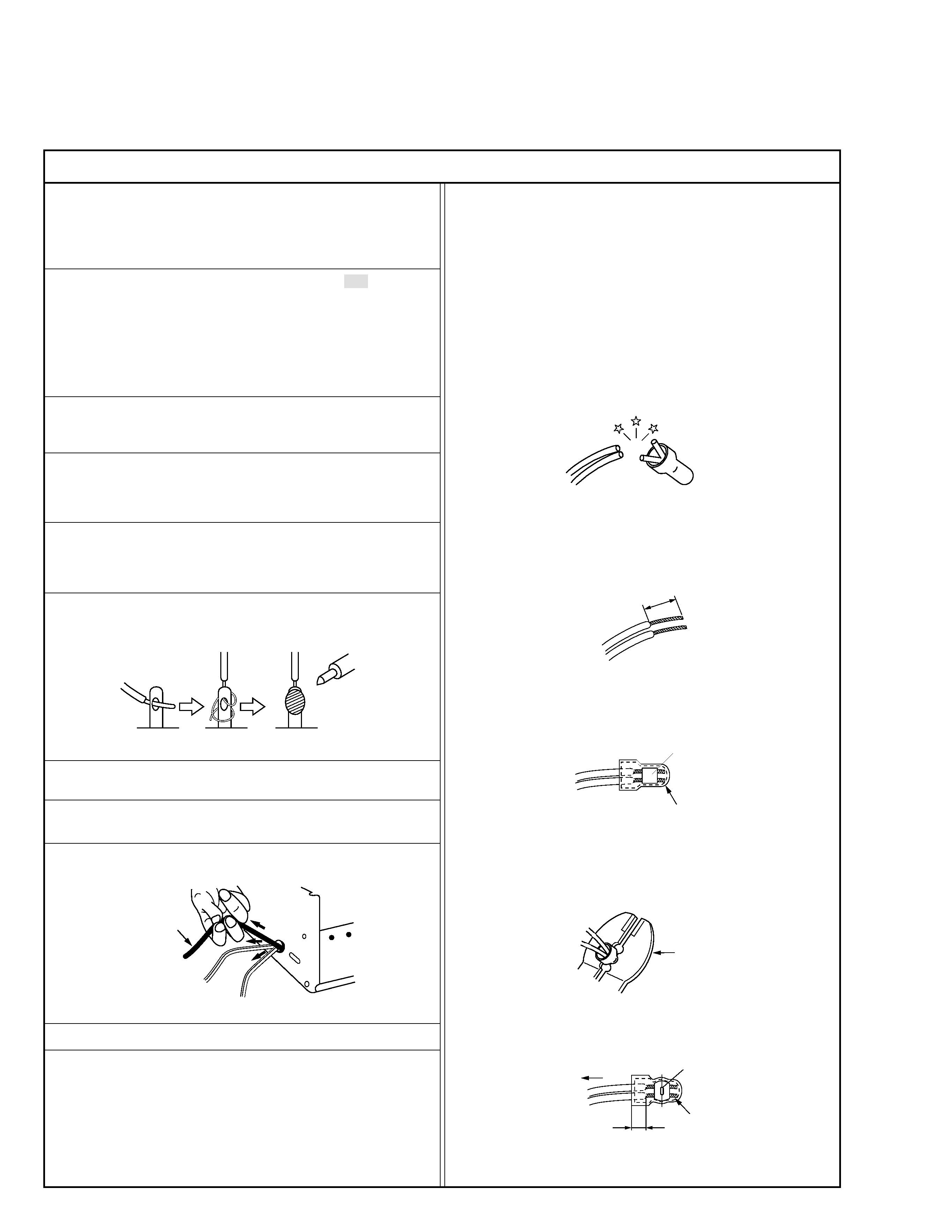
6. When replacing AC primary side components (transformers, power
cords, noise blocking capacitors, etc.) wrap ends of wires securely
about the terminals before soldering.
Power cord
Fig.2
10. Also check areas surrounding repaired locations.
11. Products using cathode ray tubes (CRTs)
In regard to such products, the cathode ray tubes themselves, the
high voltage circuits, and related circuits are specified for compli-
ance with recognized codes pertaining to X-ray emission.
Consequently, when servicing these products, replace the cath-
ode ray tubes and other parts with only the specified parts. Under
no circumstances attempt to modify these circuits.
Unauthorized modification can increase the high voltage value and
cause X-ray emission from the cathode ray tube.
12. Crimp type wire connector
In such cases as when replacing the power transformer in sets
where the connections between the power cord and power trans-
former primary lead wires are performed using crimp type connec-
tors, if replacing the connectors is unavoidable, in order to prevent
safety hazards, perform carefully and precisely according to the
following steps.
1) Connector part number : E03830-001
2) Required tool : Connector crimping tool of the proper type which
will not damage insulated parts.
3) Replacement procedure
(1) Remove the old connector by cutting the wires at a point
close to the connector.
Important : Do not reuse a connector (discard it).
Fig.7
cut close to connector
Fig.3
(2) Strip about 15 mm of the insulation from the ends of the
wires. If the wires are stranded, twist the strands to avoid
frayed conductors.
15 mm
Fig.4
(3) Align the lengths of the wires to be connected. Insert the
wires fully into the connector.
Connector
Metal sleeve
Fig.5
(4) As shown in Fig.6, use the crimping tool to crimp the metal
sleeve at the center position. Be sure to crimp fully to the
complete closure of the tool.
I
·Precautions during Servicing
7. Observe that wires do not contact heat producing parts (heatsinks,
oxide metal film resistors, fusible resistors, etc.)
8. Check that replaced wires do not contact sharp edged or pointed
parts.
9. When a power cord has been replaced, check that 10-15 kg of
force in any direction will not loosen it.
1.2
5
2.0
5.5
Crimping tool
Fig.6
(5) Check the four points noted in Fig.7.
Not easily pulled free
Crimped at approx. center
of metal sleeve
Conductors extended
Wire insulation recessed
more than 4 mm
S40888-01