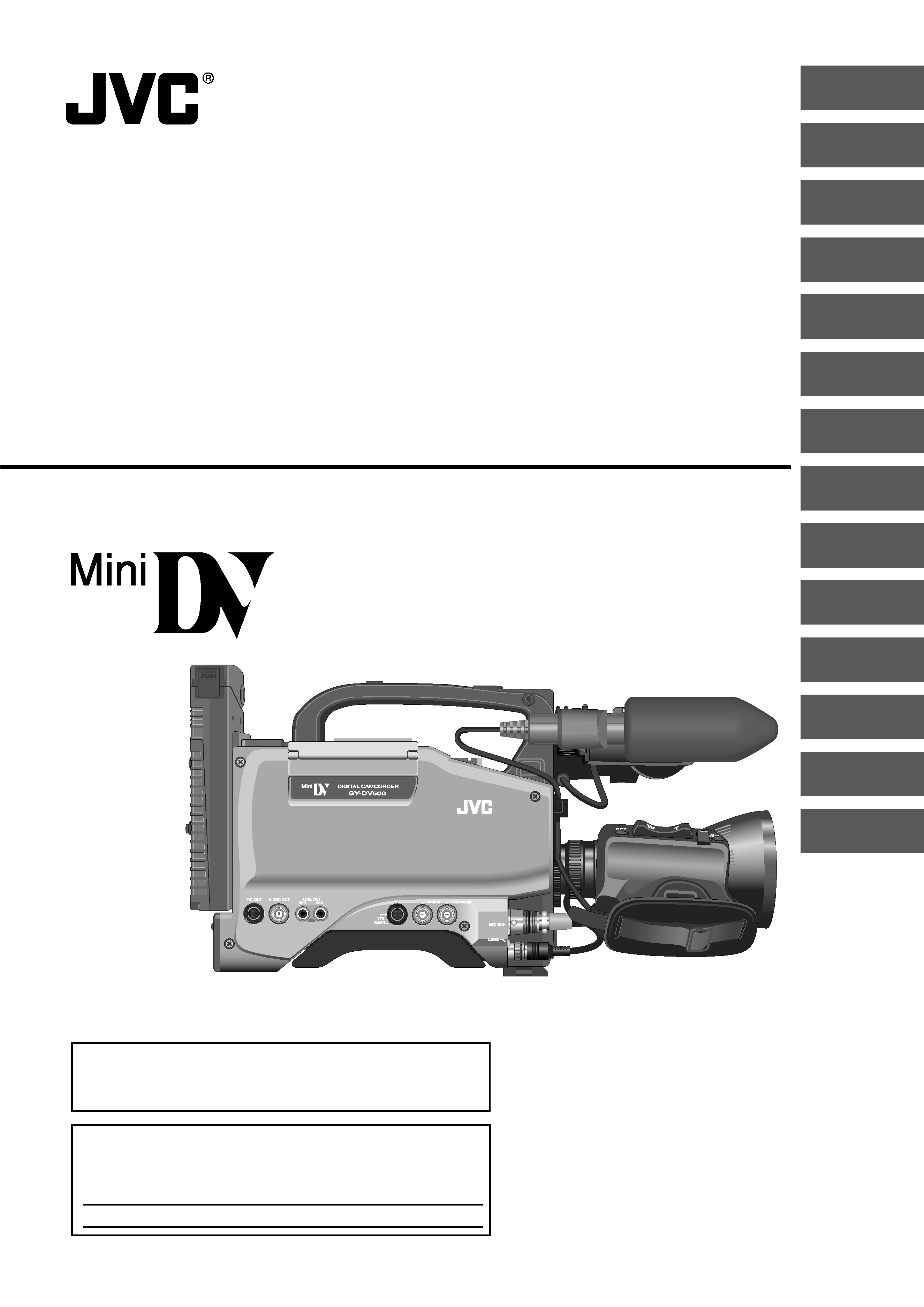
GY-DV500
SC96874-003
DV CAMCORDER
INSTRUCTIONS
*
The illustration shows the GY-DV500 DV Camcorder with the optional lens viewfinder attached.
This instruction manual is made from 100% recycled paper.
For Customer Use :
Enter below the Serial No. which is located on the body.
Retain this information for future reference.
Model No. GY-DV500
Serial No.
Thank you for purchasing this JVC product. Before operating
this unit, please read the instructions carefully to ensure the
best possible performance.
INTRODUCTION
CONTROLS,
INDICATORS AND
CONNECTORS
BASIC SYSTEM
CONNECTIONS AND
ADJUSTMENTS
POWER SUPPLY
PREPARATIONS
SETTING AND
ADJUSTMENTS
BEFORE SHOOTING
SHOOTING
OPERATION
PLAYBACK MODE
TIME CODE
OPERATION
S.S.F. (Super Scene
Finder)
USING EXTERNAL
COMPONENTS
SETUP MENU
OTHERS
FEATURES OF THE
CAMERA SECTION
,,,
,,,
yyy
yyy

2
1. Read all of these instructions.
2. Save these instructions for later use.
3. All warnings on the product and in the operating instructions should be adhered to.
4. Unplug this appliance system from the wall outlet before cleaning. Do not use liquid cleaners or aerosol cleaners.
Use a damp cloth for cleaning.
5. Do not use attachments not recommended by the appliance manufacturer as they may cause hazards.
6. Do not use this appliance near water for example, near a bathtub, washbowl, kitchen sink, or laundry tub, in a wet
basement, or near a swimming pool, etc.
7. Do not place this appliance on an unstable cart, stand, or table. The appliance may fall, caus-
ing serious injury to a child or adult, and serious damage to the appliance.
Use only with a cart or stand recommended by the manufacturer, or sold with the appliance.
Wall or shelf mounting should follow the manufacturer's instructions, and should use a mounting
kit approved by the manufacturer.
An appliance and cart combination should be moved with care. Quick stops, excessive force,
and uneven surfaces may cause the appliance and cart combination to overturn.
8. Slots and openings in the cabinet and the back or bottom are provided for ventilation, and to
insure reliable operation of the appliance and to protect it from overheating, these openings
must not be blocked or covered. The openings should never be blocked by placing the appliance on a bed, sofa, rug,
or other similar surface. This appliance should never be placed near or over a radiator or heat register. This appliance
should not be placed in a built-in installation such as a bookcase unless proper ventilation is provided.
9. This appliance should be operated only from the type of power source indicated on the marking label. If you are not
sure of the type of power supplied to your home, consult your dealer or local power company. For appliance designed
to operate from battery power, refer to the operating instructions.
10. This appliance system is equipped with a 3-wire grounding type plug (a plug having a third (grounding) pin). This plug
will only fit into a grounding-type power outlet. This is a safety feature. If you are unable to insert the plug into the
outlet, contact your electrician to replace your obsolete outlet. Do not defeat the safety purpose of the grounding
plug.
11. For added protection for this product during a lightning storm, or when it is left unattended and unused for long
periods of time, unplug it from the wall outlet and disconnect the antenna or cable system. This will prevent damage
to the product due to lightning and power-line surges.
12. Do not allow anything to rest on the power cord. Do not locate this appliance where the cord will be abused by
persons walking on it.
13. Follow all warnings and instructions marked on the appliance.
14. Do not overload wall outlets and extension cords as this can result in fire or electric shock.
15. Never push objects of any kind into this appliance through cabinet slots as they may touch dangerous voltage points
or short out parts that could result in a fire or electric shock. Never spill liquid of any kind on the appliance.
16. Do not attempt to service this appliance yourself as opening or removing covers may expose you to dangerous
voltage or other hazards. Refer all servicing to qualified service personnel.
17. Unplug this appliance from the wall outlet and refer servicing to qualified service personnel under the following
conditions:
a. When the power cord or plug is damaged or frayed.
b. If liquid has been spilled into the appliance.
c. If the appliance has been exposed to rain or water.
d. If the appliance does not operate normally by following the operating instructions. Adjust only those controls that
are covered by the operating instructions as improper adjustment of other controls may result in damage and will
often require extensive work by a qualified technician to restore the appliance to normal operation.
e. If the appliance has been dropped or the cabinet has been damaged.
f.
When the appliance exhibits a distinct change in performance this indicates a need for service.
18. When replacement parts are required, be sure the service technician has used replacement parts specified by the
manufacturer that have the same characteristics as the original part. Unauthorized substitutions may result in fire,
electric shock, or other hazards.
19. Upon completion of any service or repairs to this appliance, ask the service technician to perform routine safety
checks to determine that the appliance is in safe operating condition.
IMPORTANT SAFEGUARDS
3
SAFETY PRECAUTIONS
FOR USA AND CANADA
RISK OF ELECTRIC SHOCK
DO NOT OPEN
AUTION :
TO REDUCE THE RISK OF ELECTRIC SHOCK,
DO NOT REMOVE COVER (OR BACK).
NO USER SERVICEABLE PARTS INSIDE.
REFER SERVICING TO QUALIFIED SERVICE PERSONNEL.
The exclamation point within an equilateral triangle is
intended to alert the user to the presence of important
operating and maintenance (servicing) instructions in
the literature accompanying the appliance.
The lightning flash with arrowhead symbol, within an
equilateral triangle is intended to alert the user to the
presence of uninsulated "dangerous voltage" within the
product's enclosure that may be of sufficient magni-
tude to constitute a risk of electric shock to persons.
INFORMATION
This equipment has been tested and found to comply with the limits
for a Class B digital device, pursuant to Part 15 of the FCC Rules.
These limits are designed to provide reasonable protection against
harmful interference in a residential installation. This equipment
generates, uses, and can radiate radio frequency energy and, if not
installed and used in accordance with the instructions, may cause
harmfull interfrence to radio communications. However, there is no
guarantee that interference will not occur in a particular installation.
If this equipment does cause harmful interference to radio or
television reception, which can be determined by turning the
equipment off and on, the user is encouraged to try to correct the
interference by one or more of the following measures:
Reorient or relocate the receiving antenna.
Increase the separation between the equipment and receiver.
Connect the equipment into an outlet on a circuit different from
that to which the receiver is connected.
Consult the dealer or an experienced radio/TV technician for help.
CAUTION
CHANGES OR MODIFICATIONS NOT APPROVED BY JVC
COULD VOID USER'S AUTHORITY TO OPERATE THE
EQUIPMENT.
INFORMATION FOR USA
THIS DEVICE COMPLIES WITH PART 15 OF THE FCC RULES.
OPERATION IS SUBJECT TO THE FOLLOWING TWO
CONDITIONS : (1) THIS DEVICE MAY NOT CAUSE HARMFUL
INTERFERENCE, AND (2) THIS DEVICE MUST ACCEPT ANY
INTERFERENCE RECEIVED, INCLUDING INTERFERENCE
THAT MAY CAUSE UNDESIRED OPERATION
INFORMATION (FOR CANADA)
RENSEIGNEMENT (POUR CANADA)
This Class B digital apparatus complies with Canadian
ICES-003.
Cet appareil numérique de la Class B est conforme à la norme
NMB-003 du Canada.
CAUTION
NOTE:
The rating plate (serial number plate) is on the top frame.
WARNING:
TO REDUCE THE RISK OF FIRE OR ELECTRIC
SHOCK, DO NOT EXPOSE THIS APPLIANCE TO
RAIN OR MOISTURE.
This unit should be used with 12V DC only.
CAUTION:
To prevent electric shocks and fire hazards, do NOT use
any other power source.
CAUTION
To prevent electric shock, do not open the cabinet. No user servicea-
ble parts inside. Refer servicing to qualified service personnel.
AVERTISSEMENT :
POUR EVITER LES RISQUES D'INCENDIE OU
D'ELECTROCUTION, NE PAS EXPOSER
L'APPAREIL A L'HUMIDITE OU A LA PLUIE.
Ce magnétoscope ne doit être utilisé que sur du courant
direct en 12V.
ATTENTION :
Afin d'eviter tout resque d'incendie ou d'électrocution,
ne pas utillser d'autres sources d'alimentation électrique.
REMARQUE :
La plaque d'identification (numéro de série) se trouve sur le panneau
arrière de l'appareil.
WARNING ON LITHIUM BATTERY
The battery used in this device may present a fire or chemical burn
hazard if mistreated. Do not recharge, disassemble, heat avobe 100
°C
(212
°F) or incinerate.
Replace battery with Matsushita Electric CR2032, use of another
battery may present a risk of fire or explosion.
· Dispose of used battery promptly.
· Keep away from children.
· Do not disassemble and do not dispose of in fire.

4
Thank you for purchasing the DV Camcorder GY-DV500.
These instructions are for GY-DV500U.
This unit is a MiniDV video system format camcorder.
Videocassettes which are not marked with the MiniDV
symbol cannot be used with this unit.
MAIN FEATURES
The following phenomena may occur when tapes recorded
on other units (including another GY-DV500) are recorded
or played back on this camcorder.
The transient section between scenes recorded on other
units and those recorded on this unit may appear
disturbed.
Digital noise may appear during playback due to tracking
errors.
Compact, lightweight design
Employment of magnesium die cast has resulted in an
operation-condition weight as low as approximately 5 kg
including lens, viewfinder, battery, and cassette.
DV high-quality digital format
The 4:1:1, 8-bit, 25 Mbps component digital processing of
the format ensures recording and playback with high picture
quality.
High sound quality thanks to PCM audio
Two types of sampling, 16-bit, 48 kHz sampling and 12-bit,
32 kHz sampling, ensure high-quality digital audio.
Concentrated LCD display (back-lit)
The concentrated LCD panel shows the time code and CTL
counter, tape remaining time, remaining battery power, audio
levels, VCR section setup menus, hour meter data, and a
variety of warning indications. The display is back-lit to
facilitate viewing in dark locations.
Time code reader/generator
The built-in time code reader/generator can be used to record
SMPTE time code and user's bits.
AEF (Automatic Edit Function) enables neat switching
between recorded scenes.
Built-in monitor loudspeaker for audio checking
The input audio can be monitored in recording or EE mode.
The playback sound can be monitored in the playback mode.
The loudspeaker also outputs an alarm tone in case an
abnormal condition occurs in the unit.
Rec check function for convenient recording review
Camera section designed with 3-CCD system for high-quality
picture
Three 1/2" CCDs with 380,000 effective pixels employed.
Digital signal processing for reproduction of DV high-quality
picture.
Super sensitivity F/11, 2000 lux
2000 lux standard sensitivity increased to F/11 while high S/
N is retained. Enables shooting at normal indoor illumination
eliminating the need for extra illumination.
LOLUX for 0.75 lux (F1.4) illumination
Employment of LOLUX mode ensures +33 dB gain. This is
ideal for difficult shooting conditions with almost no
illumination.
Multi-Zone Auto Iris Detection Circuit
Multi-zone auto iris detection circuit ensures optimum iris
position even in backlit conditions or when a bright subject
moves in a frame. Switch provided for selecting over or under
level.
Safety Zone indication in viewfinder
Three types of safety zone indicator functions provided.
Zebra pattern video level indication in viewfinder
Full Auto Shooting (FAS) function
Eliminating the need for troublesome switch or filter
operations, the FAS function automatically provides a wide
range of compatibility with shooting conditions which varies
as you move between indoors and outdoors or between bright
and dark locations.
Color temperature conversion filters for "3200K", "5600K",
"5600 K + ND" provided.
Variable scan shutter
Eliminates flicker when shooting other screen pictures than
NTSC, such as computer monitor screens.
Copes with the range from 60.1 Hz to 2084.6 Hz.
DV (i. LINK) connector
DV connector (4-pin) provided. Enables transfer of digital data
to other equipment provided with DV connector, such as a
non-linear editing controller.
S.S.F. (Super Scene Finder) function
Enables memorization of the start point and ending point of
each scene or memorization of CUE points.
1/2" bayonet type lens
Camera output, VCR playback output (composite/YC) possible
External sync input connector
Built-in color bar (SMPTE type)
Superior operability with shutter speed and menus selected
by dial.
This unit records and plays back in the SP mode.
Recording or playback in the LP mode is not possible.
Due to manufacturing dispersion of tapes, we
recommend not to record pictures within the first 2 to 3
minutes from the beginning of the tape.
Before recording important scenes, be sure to perform a
test recording and confirm that both video and audio are
recorded correctly.
Recorded video and audio contents are for private use.
Other use may infringe on the rights of copyright holders.
JVC cannot assume liabilities that may derive from the
impossibility of normal recording or playback of video or
audio due to malfunction of the camcorder or the
videocassette.

5
CONTENTS
INTRODUCTION
MAIN FEATURES ............................................................... 4
1. INTRODUCTION
1-1
Main Unit Configuration .............................................. 6
1-2
Precautions for Proper Use ........................................ 7
1-3
Routine and Periodical Maintenance ......................... 8
1-4
Videocassette to be Used .......................................... 8
1-5
Battery Pack to be Used ............................................ 9
1-6
Condensation ............................................................. 9
1-7
Characteristic CCD Phenomena ................................ 9
2. CONTROLS, INDICATORS AND CONNECTORS
2-1
Front Section ............................................................ 10
2-2
Right Side Section .................................................... 12
2-3
Left Side Section ...................................................... 18
2-4
Top Section .............................................................. 19
2-5
Rear Section ............................................................ 20
2-6
Counter Display Contents ........................................ 22
2-7
Lens (optional) ......................................................... 23
2-8
1.5-Inch Viewfinder (optional) ................................... 24
2-9
Indications in Viewfinder ........................................... 25
· Warning LED Indicators Inside the Viewfinder ....... 25
· Viewfinder Screen Display ..................................... 25
5. PREPARATIONS
5-1
Turning the Power ON .............................................. 39
5-2
Cassette Loading and Unloading ............................. 40
5-3
Setting the Date and Time ........................................ 41
6. SETTING AND ADJUSTMENTS BEFORE
SHOOTING
6-1
Camera Settings ...................................................... 42
6-2
Viewfinder Adjustment ............................................. 43
6-3
External Monitor Adjustment .................................... 43
6-4
Back Focus Adjustment ............................................ 44
6-5
White Balance Adjustment ....................................... 45
· White Balance Adjustment ..................................... 45
· Full-Time Auto White Balance (FAW) ..................... 45
6-6
Switch Settings of the VCR Section ......................... 46
6-7
Audio Input Signal Selection .................................... 47
6-8
Recording Level Adjustment .................................... 48
6-9
Monitoring Audio during Recording .......................... 49
7. SHOOTING OPERATION
7-1
Basic Recording Operation ...................................... 50
7-2
VCR Save Mode ....................................................... 52
7-3
If Unit is Left in Record-Pause (Standby) Mode ....... 52
7-4
Checking Recorded Contents in Record-Pause Mode
(Recording Check Function) .................................... 53
8. PLAYBACK MODE
8-1
Playback Procedure ................................................. 54
8-2
Fast-Forward, Rewind .............................................. 55
8-3
Search ...................................................................... 55
BASIC OPERATIONS
APPLICATION
9. TIME CODE OPERATION
9-1
Displaying Time Code .............................................. 56
9-2
Presetting and Recording of Time Code .................. 56
· Time Code Presetting Procedure ........................... 57
· Presetting User's Bit Data ...................................... 57
9-3
Recording Time Codes in Continuation of
Time Codes Recorded on Tape ............................... 58
9-4
Reproducing Time Codes ......................................... 59
10. S.S.F. (Super Scene Finder) FUNCTION
10-1 Explanation of the S.S.F. Function ........................... 60
10-2 How to Use the S.S.F. Function ................................ 61
10-3 Deleting S.S.F. Data ................................................. 62
10-4 Resetting S.S.F. Data ............................................... 62
10-5 Writing S.S.F. Data to Tape ....................................... 63
10-6 Outputting S.S.F. Data .............................................. 63
PREPARATIONS
3. BASIC SYSTEM CONNECTIONS AND
ADJUSTMENTS
3-1
Basic System ........................................................... 30
3-2
Attaching the Zoom Lens (optional) ......................... 31
3-3
Attaching the Viewfinder ........................................... 31
3-4
Attaching the Microphone (provided) ....................... 32
3-5
Attaching the Microphone (optional) ........................ 32
3-6
Attaching the Tripod Base (provided) ....................... 33
3-7
Inserting and Replacing Backup Lithium Batteries .. 34
4. POWER SUPPLY
4-1
AC Operation ........................................................... 35
4-2
Battery Pack Operation ............................................ 35
· Attaching a Flat Shape Type Battery Pack ............. 36
· Using an Anton-Bauer Battery Pack ...................... 37
· Remaining Battery Power Display/Precautions for
the Battery Pack ..................................................... 38