SERVICE MANUAL
No. 86656
December 2001
SPECIFICATIONS (The specifications shown pertain specifically to the model GR-SXM745)
COMPACT VHS CAMCORDER
Printed in Japan
This service manual is printed on 100% recycled paper.
COPYRIGHT © 2001 VICTOR COMPANY OF JAPAN, LTD.
GR-SXM340U,SXM740U
No.
86656
GR-SXM340U,SXM740U
JVC SERVICE & ENGINEERING COMPANY OF AMERICA
DIVISION OF JVC AMERICAS CORP.
Head office
East Coast
Midwest
West Coast
Atlanta
Hawaii
:
:
:
:
:
:
1700 Valley Road Wayne, New Jersey 07470-9976
10 New Maple Avenue Pine Brook, New Jersey 07058-9641
705 Enterprise Street Aurora, Illinois 60504-8149
5665 Corporate Avenue Cypress, California 90630-0024
1500 Lakes Parkway Lawrenceville, Georgia 30043-5857
2969 Mapunapuna Place Honolulu, Hawaii 96819-2040
(973)317-5000
(973)396-1000
(630)851-7855
(714)229-8011
(770)339-2582
(808)833-5828
JVC CANADA INC.
Head office
Montreal
Vancouver
:
:
:
21 Finchdene Square Scarborough, Ontario M1X 1A7
16800 Rte Trans-Canadienne, Kirkland, Quebec H9H 5G7
13040 Worster Court Richmond, B.C. V6V 2B3
(416)293-1311
(514)871-1311
(604)270-1311
S40895-04
Specifications shown are for SP mode unless otherwise indicated. E & O.E. Design
and specifications subject to change without notice.
Camcorder
General
Format
: S-VHS/VHS NTSC standard
Power source
: DC 11 V
(Using AC Adapter)
DC 6 V
(Using battery pack)
Power consumption
Viewfinder on
: 4.0 W
LCD monitor on
: 4.5 W
Video light
: 3.0 W
Signal system
: NTSC-type
Video recording system
Luminance
: FM recording
Color
: Converted sub-carrier direct recording
Conforms to VHS standard
Cassette
:
/
cassette
Tape speed
SP
: 33.35 mm/sec. (1-5/16 ips)
EP
: 11.12 mm/sec. (7/16 ips)
Recording time (max.)
SP
: 40 minutes
EP
: 120 minutes
(with TC-40 cassette)
Operating
temperature
: 0°C to 40°C (32°F to 104°F)
Operating humidity : 35% to 80%
Storage temperature : 20°C to 50°C (4°F to 122°F)
Weight
: Approx. 930 g (2.1 lbs)
Dimensions
: 200 mm x 112 mm x 118 mm
(W x H x D)
(7-7/8" x 4-7/16" x 4-11/16")
(with the LCD monitor closed and with the viewfinder
fully tilted downward)
Pickup
: 1/4" format CCD
Lens
: F1.6, f = 3.9 mm to 62.4 mm,
16:1 power zoom lens with auto iris and macro control,
filter diameter 40.5 mm
Viewfinder
: Electronic viewfinder with 0.5" black/white CRT
White balance
adjustment
: Auto/Manual adjustment
Some accessories are not available in some areas. Please consult your
nearest JVC dealer for details on accessories and their availability.
LCD monitor
: 3.5" diagonally measured, LCD panel/TFT active
matrix system
Speaker
: Monaural
Connectors
Video
: 1 V (p-p), 75
unbalanced, analog output (via
Video output connector)
Audio
: 300 mV (rms), 1 k
analog output
(via Audio output connector)
Digital
: ø3.5 mm, 4-pole, mini-head jack
S-Video
: Y : 1 V (p-p), 75
, analog output
C : 0.29 V (p-p), 75
, analog output
AC Adapter
Power requirement
U.S.A. and Canada : AC 120 V`, 60 Hz
Other countries
: AC 110 V to 240 V`,
50 Hz/60 Hz
Output
: DC 11 V
, 1 A
Optional Accessories
· Battery Packs BN-V12U, BN-V20U, BN-V400U
· A/V (Audio/Video) Cable
· Compact S-VHS (
) Cassettes ST-C-40/30/20
· Compact VHS (
) Cassettes TC-40/30/20
· Active Carrying Bag CB-V7U

4. CHARTS AND DIAGRAMS
NOTES OF SCHEMATIC DIAGRAM .......................................... 4-1
CIRCUIT BOARD NOTES ........................................................... 4-2
4.1 BOARD INTERCONNECTIONS .......................................... 4-3
4.2 CPU SCHEMATIC DIAGRAM .............................................. 4-5
4.3 M. MDA SCHEMATIC DIAGRAM ......................................... 4-7
4.4 VTR ASP SCHEMATIC DIAGRAM ....................................... 4-9
4.5 DSP SCHEMATIC DIAGRAM ............................................. 4-11
4.6 F/Z/I/MDA SCHEMATIC DIAGRAM .................................... 4-13
4.7 V OUT SCHEMATIC DIAGRAM ......................................... 4-15
4.8 TG/CDS SCHEMATIC DIAGRAM ...................................... 4-17
4.9 REG SCHEMATIC DIAGRAM ............................................ 4-19
4.10 LCD/CVF SCHEMATIC DIAGRAM .................................. 4-21
4.11 BW/CVF SCHEMATIC DIAGRAM ................................... 4-23
4.12 JACK SCHEMATIC DIAGRAM ........................................ 4-25
4.13 SPEAKER SCHEMATIC DIAGRAM ................................ 4-27
4.14 CCD SCHEMATIC DIAGRAM .......................................... 4-28
4.15 MONITOR SCHEMATIC DIAGRAM ................................. 4-29
4.16 E. VF SCHEMATIC DIAGRAM ......................................... 4-31
4.17 TOP OPE UNIT, ZOOM UNIT, REAR UNIT AND SENSOR
SCHEMATIC DIAGRAMS ................................................ 4-33
4.18 MAIN CIRCUIT BOARD ................................................... 4-35
4.19 MONITOR CIRCUIT BOARD ........................................... 4-41
4.20 CCD CIRCUIT BOARD .................................................... 4-43
4.21 E. VF CIRCUIT BOARD ................................................... 4-44
4.22 WAVEFORMS .................................................................. 4-45
4.23 VOLTAGE CHARTS ......................................................... 4-46
4.24 POWER SYSTEM BLOCK DIAGRAM ............................. 4-51
4.25 CPU/MDA SYSTEM BLOCK DIAGRAM .......................... 4-53
4.26 CAMERA AND Y/C SYSTEM BLOCK DIAGRAM ........... 4-55
4.27 MONITOR SYSTEM BLOCK DIAGRAM ......................... 4-59
5. PARTS LIST
5.1 PACKING AND ACCESSORY ASSEMBLY <M1> ................ 5-1
5.2 FINAL ASSEMBLY <M2> ..................................................... 5-2
5.3 MECHANISM ASSEMBLY <M3> ......................................... 5-6
5.4 ELECTRONIC VIEWFINDER ASSEMBLY <M4> ................. 5-8
5.5 MONITOR ASSEMBLY <M5> [GR-SXM340U] .................... 5-9
5.5 MONITOR ASSEMBLY <M5> [GR-SXM740U] .................. 5-10
5.6 ELECTRICAL PARTS LIST ................................................ 5-11
MAIN BOARD ASSEMBLY <01> ............................................. 5-11
CCD BOARD ASSEMBLY <02> .............................................. 5-17
MONITOR BOARD ASSEMBLY <07> ..................................... 5-17
ELECTRONIC VIEWFINDER BOARD ASSEMBLY <60> ....... 5-18
Important Safety Precautions
INSTRUCTIONS
1. DISASSEMBLY
1.1 SERVICE CAUTIONS .......................................................... 1-1
1.1.1 Precautions ..................................................................... 1-1
1.1.2 How to read the disassembly and assembly ................... 1-1
1.1.3 Connection of the wires ................................................... 1-1
1.2 TOOLS REQUIRED FOR ADJUSTMENTS ......................... 1-2
1.3 DISASSEMBLY/ASSEMBLY OF CABINET PARTS .............. 1-3
1.3.1 Disassembly flow chart .................................................... 1-3
1.3.2 Disassembly method ....................................................... 1-4
1.4 DISASSEMBLY/ASSEMBLY OF CAMERA SECTION AND
DECK SECTION ................................................................ 1-10
1.4.1 Flowchart of disassembly .............................................. 1-10
1.4.2 Disassembly method ..................................................... 1-10
1.5 REPLACEMENT OF CCD IMAGE SENSOR ..................... 1-12
1.5.1 Removal of CCD image sensor ..................................... 1-12
1.5.2 Installation of new CCD image sensor .......................... 1-12
1.5.3 Replacement of CCD board assy .................................. 1-12
1.6 TAKE OUT CASSETTE TAPE ............................................ 1-13
1.7 EMERGENCY DISPLAY .................................................... 1-14
1.8 DEMONSTRATION MODE ................................................ 1-14
1.9 SERVICE NOTE ................................................................. 1-16
2. MECHANISM ADJUSTMENT
2.1 SERVICE CAUTIONS ............................................................ 2-1
2.1.1 Precautions ..................................................................... 2-1
2.1.2 How to read the disassembly and assembly
(For Mechanism Parts) .................................................... 2-1
2.2 DISASSEMBLY/ASSEMBLY OF MECHANISM PARTS ....... 2-2
2.3 CHECKUP AND ADJUSTMENT OF MECHANISM PHASE 2-6
2.4 TAPE TRANSPORT ADJUSTMENT .................................... 2-7
2.4.1 Back tension .................................................................... 2-7
2.4.2 Tape pattern .................................................................... 2-7
2.4.3 A/C head height & azimuth .............................................. 2-8
2.4.4 Phase of control head (X value) ...................................... 2-9
2.5 REMARKS ............................................................................ 2-9
2.5.1 Cleaning .......................................................................... 2-9
2.5.2 Applying oil and grease ................................................... 2-9
2.5.3 Checkup .......................................................................... 2-9
2.6 JIG CONNECTOR CABLE CONNECTION ........................ 2-10
3. ELECTRICAL ADJUSTMENT
3.1 ELECTRICAL ADJUSTMENT .............................................. 3-1
3.1.1 PREPARATION ................................................................ 3-1
3.2 ELECTRONIC VIEWFINDER (E. VF) ADJUSTMENT .......... 3-2
3.2.1 Tilt .................................................................................... 3-2
3.2.2 Centering ......................................................................... 3-2
3.2.3 Vertical scanning ............................................................. 3-2
3.2.4 Brightness ....................................................................... 3-2
3.2.5 Focus ............................................................................... 3-2
TABLE OF CONTENTS
Section
Title
Page
Section
Title
Page
GR-SXM340U
GR-SXM740U
BODY COLOR
METALLIC GRAY
SLIVER
LCD MONITOR
2.5"
3.5"
PB ZOOM FUNCTION
NOT USED
USED
A DUBBING FUNCTION
NOT USED
USED
V INSERT FUNCTION
NOT USED
USED
The following table lists the differing points between Models GR-SXM340U and GR-SXM740U in this serise.
Important Safety Precautions
Prior to shipment from the factory, JVC products are strictly inspected to conform with the recognized product safety and electrical codes of the
countries in which they are to be sold. However, in order to maintain such compliance, it is equally important to implement the following precautions
when a set is being serviced.
Fig.1
1. Locations requiring special caution are denoted by labels and in-
scriptions on the cabinet, chassis and certain parts of the product.
When performing service, be sure to read and comply with these
and other cautionary notices appearing in the operation and serv-
ice manuals.
2. Parts identified by the
! symbol and shaded (
) parts are
critical for safety.
Replace only with specified part numbers.
Note: Parts in this category also include those specified to com-
ply with X-ray emission standards for products using
cathode ray tubes and those specified for compliance
with various regulations regarding spurious radiation
emission.
3. Fuse replacement caution notice.
Caution for continued protection against fire hazard.
Replace only with same type and rated fuse(s) as specified.
4. Use specified internal wiring. Note especially:
1) Wires covered with PVC tubing
2) Double insulated wires
3) High voltage leads
5. Use specified insulating materials for hazardous live parts. Note
especially:
1) Insulation Tape
3) Spacers
5) Barrier
2) PVC tubing
4) Insulation sheets for transistors
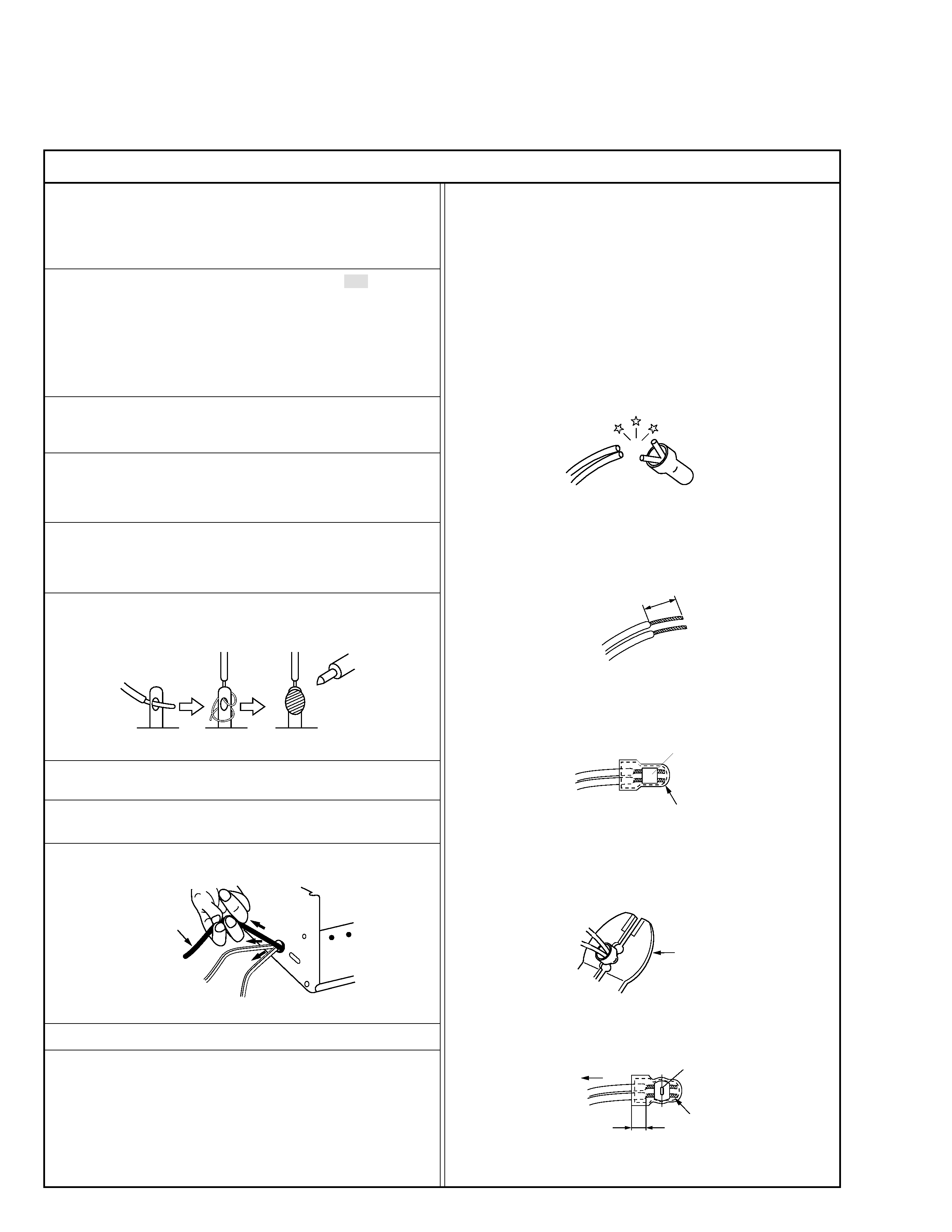
6. When replacing AC primary side components (transformers, power
cords, noise blocking capacitors, etc.) wrap ends of wires securely
about the terminals before soldering.
Power cord
Fig.2
10. Also check areas surrounding repaired locations.
11. Products using cathode ray tubes (CRTs)
In regard to such products, the cathode ray tubes themselves, the
high voltage circuits, and related circuits are specified for compli-
ance with recognized codes pertaining to X-ray emission.
Consequently, when servicing these products, replace the cath-
ode ray tubes and other parts with only the specified parts. Under
no circumstances attempt to modify these circuits.
Unauthorized modification can increase the high voltage value and
cause X-ray emission from the cathode ray tube.
12. Crimp type wire connector
In such cases as when replacing the power transformer in sets
where the connections between the power cord and power trans-
former primary lead wires are performed using crimp type connec-
tors, if replacing the connectors is unavoidable, in order to prevent
safety hazards, perform carefully and precisely according to the
following steps.
1) Connector part number : E03830-001
2) Required tool : Connector crimping tool of the proper type which
will not damage insulated parts.
3) Replacement procedure
(1) Remove the old connector by cutting the wires at a point
close to the connector.
Important : Do not reuse a connector (discard it).
Fig.7
cut close to connector
Fig.3
(2) Strip about 15 mm of the insulation from the ends of the
wires. If the wires are stranded, twist the strands to avoid
frayed conductors.
15 mm
Fig.4
(3) Align the lengths of the wires to be connected. Insert the
wires fully into the connector.
Connector
Metal sleeve
Fig.5
(4) As shown in Fig.6, use the crimping tool to crimp the metal
sleeve at the center position. Be sure to crimp fully to the
complete closure of the tool.
I
·Precautions during Servicing
7. Observe that wires do not contact heat producing parts (heatsinks,
oxide metal film resistors, fusible resistors, etc.)
8. Check that replaced wires do not contact sharp edged or pointed
parts.
9. When a power cord has been replaced, check that 10-15 kg of
force in any direction will not loosen it.
1.2
5
2.0
5.5
Crimping tool
Fig.6
(5) Check the four points noted in Fig.7.
Not easily pulled free
Crimped at approx. center
of metal sleeve
Conductors extended
Wire insulation recessed
more than 4 mm
S40888-01
·Safety Check after Servicing
Examine the area surrounding the repaired location for damage or deterioration. Observe that screws, parts and wires have been returned
to original positions, Afterwards, perform the following tests and confirm the specified values in order to verify compliance with safety
standards.
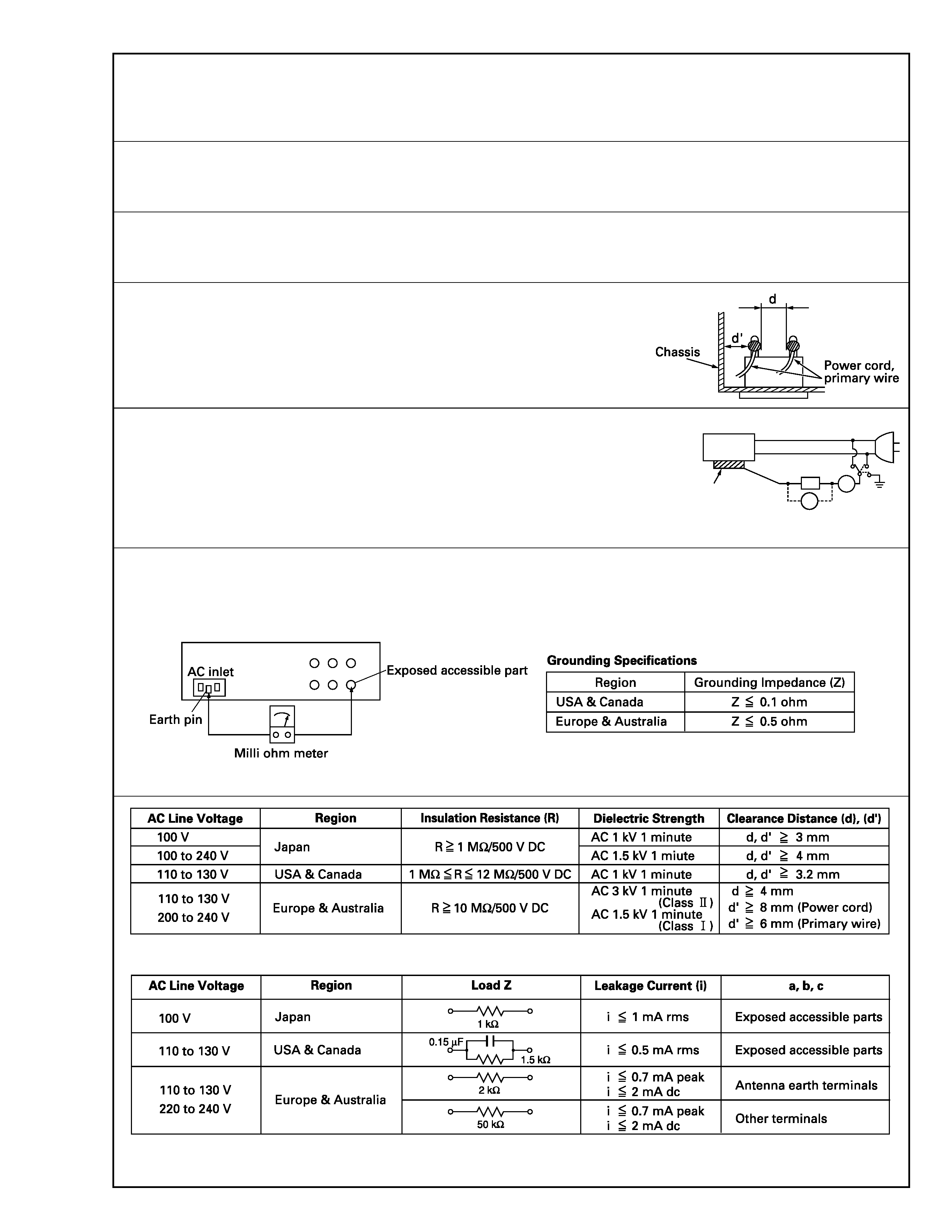
1. Insulation resistance test
Confirm the specified insulation resistance or greater between power cord plug prongs and exter-
nally exposed parts of the set (RF terminals, antenna terminals, video and audio input and output
terminals, microphone jacks, earphone jacks, etc.). See table 1 below.
2. Dielectric strength test
Confirm specified dielectric strength or greater between power cord plug prongs and exposed acces-
sible parts of the set (RF terminals, antenna terminals, video and audio input and output terminals,
microphone jacks, earphone jacks, etc.). See table 1 below.
3. Clearance distance
When replacing primary circuit components, confirm specified clearance distance (d), (d') be-
tween soldered terminals, and between terminals and surrounding metallic parts. See table 1
below.
4. Leakage current test
Confirm specified or lower leakage current between earth ground/power cord plug prongs and
externally exposed accessible parts (RF terminals, antenna terminals, video and audio input and
output terminals, microphone jacks, earphone jacks, etc.).
Measuring Method : (Power ON)
Insert load Z between earth ground/power cord plug prongs and externally exposed accessible
parts. Use an AC voltmeter to measure across both terminals of load Z. See figure 9 and following
table 2.
5. Grounding (Class 1 model only)
Confirm specified or lower grounding impedance between earth pin in AC inlet and externally exposed accessible parts (Video in, Video out,
Audio in, Audio out or Fixing screw etc.).
Measuring Method:
Connect milli ohm meter between earth pin in AC inlet and exposed accessible parts. See figure 10 and grounding specifications.
Fig. 10
Fig. 9
Fig. 8
Table 1 Specifications for each region
Table 2 Leakage current specifications for each region
Note: These tables are unofficial and for reference only. Be sure to confirm the precise values for your particular country and locality.
II
S40888-01
ab
c
V
A
Externally
exposed
accessible part
Z
1-1
(1)
(2)
(3)
(4)
SECTION 1
DISASSEMBLY
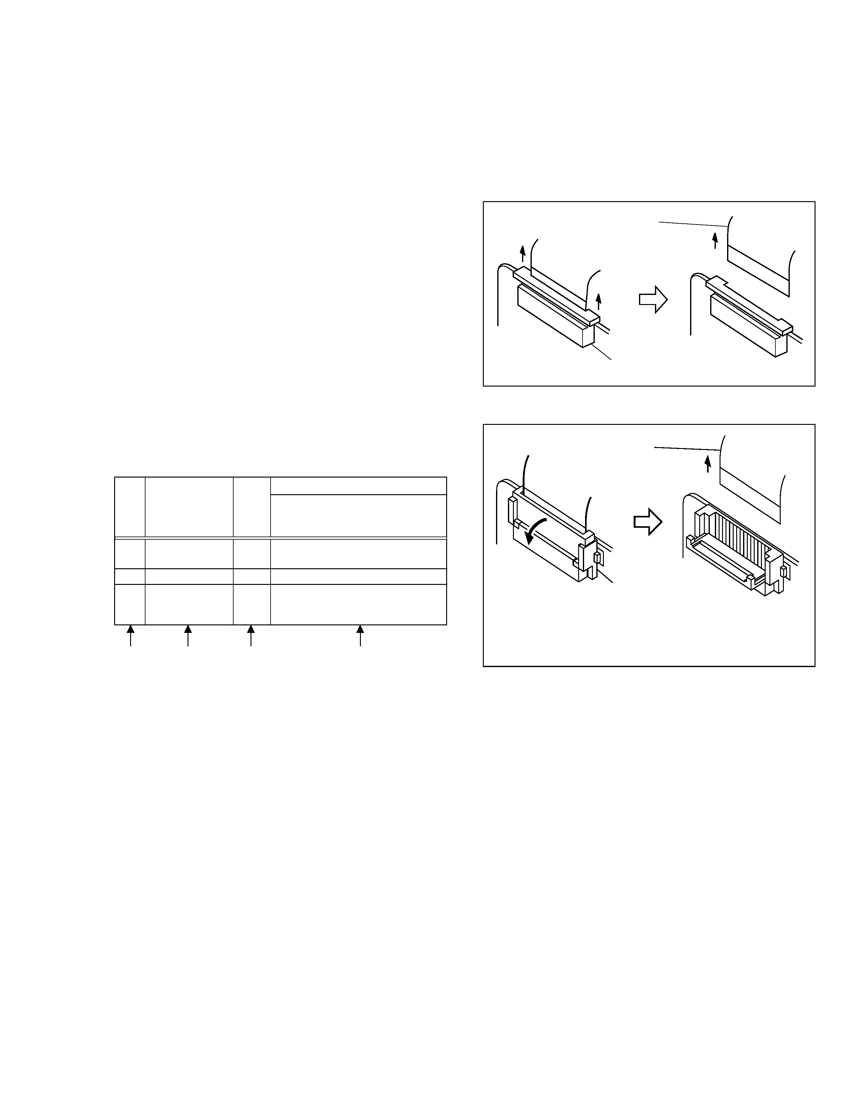
1.1.3 Connection of the wires
1. Pull the connector structure upward to release the clamp
when removing or inserting the flat wire cable.
1.1 SERVICE CAUTIONS
1.1.1
Precautions
1. Before disassembling/re-assembling the set as well as
soldering parts, make sure to disconnect the power ca-
ble.
2. When disconnecting/connecting connectors, pay enough
attention to wiring not to damage it.
3. In general, chip parts such as resistor, shorting jumpers
(0-ohm resistor), ceramic capacitors, diodes, etc. can not
be reused after they were once removed.
4. When installing parts, be careful not to do with other parts
as well as not to damage others.
5. When removing ICs, be careful not to damage circuit pat-
terns.
6. Tighten screws properly during the procedures. Un-
less specified otherwise, tighten screws at torque of
0.196 N·m (2.0 kgf·cm).
1.1.2 How to read the disassembly and assembly
(For Cabinet Parts)
(1) Order of steps in Procedure
When reassembling, preform the step(s) in the reverse
order. These numbers are also used as the identifica-
tion (location) No. of parts Figures.
(2) Part to be removed or installed.
(3) Fig. No. showing Procedure or Part Location.
C = Cabinet
CA = Camera
D = Deck
(4) Identification of part to be removed, unhooked, un-
locked, released, unplugged, unclamped or unsoldered.
P = Spring
W = Washer
S = Screw
* = Unhook, unlock, release, unplug or unsolder.
2(S3) = 2 Screws (S3)
CN = Connector
Fig. 1-1-1
Fig. 1-1-2
1
CASETTE COVER
C1
2(S1)
ASSEMBLY
2
UPPER CASE
C2
2(S2), 2(L2)
3
LOWER CASE
C3
9(S3), (L3a), (L3b)
ASSEMBLY
*CN3a,CN3b,COVER(JACK)
(Incl. E.VF ASSEMBLY)
STEP
No.
PART
Fig.
No.
REMOVAL
*UNLOCK/RELEASE/
UNPLUG/UNCLAMP/
UNSOLDER
Connector
Wire
Connector
Wire
NOTE:
After removing the wire, return the stopper to
its original position, because it is apt to come
off if it is left open.