SERVICE MANUAL
No. 86701
May 2002
This service manual is printed on 100% recycled paper.
COPYRIGHT © 2002 VICTOR COMPANY OF JAPAN, LTD.
DIGITAL VIDEO CAMERA
Regarding service information other than these sections, refer to the GR-DVL145EG-X service manual (No. 86693).
Also, be sure to note important safety precautions provided in the service manual.
GR-DVL120A
SPECIFICATIONS (The specifications shown pertain specifically to the model GR-DVL120)
Camcorder
General
Power supply
: DC 11.0 V
(Using AC Adapter)
DC 7.2 V
(Using battery pack)
Power consumption
LCD monitor off, viewfinder on
: Approx. 4.3 W
LCD monitor on, viewfinder off
: Approx. 5.3 W
Dimensions (W x H x D)
: 83 mm x 94 mm x 223 mm
(with the LCD monitor closed and the viewfinder
pushed down)
Weight
: Approx. 630 g
Operating temperature
: 0°C to 40°C
Operating humidity
: 35% to 80%
Storage temperature
: 20°C to 50°C
Pickup
: 1/4" CCD
Lens
: F 1.6, f = 3.9 mm to 62.4 mm, 16:1 power zoom lens
Filter diameter
: ø40.5 mm
LCD monitor
: 2.5" diagonally measured, LCD panel/TFT active matrix
system
Viewfinder
: Electronic viewfinder with 0.24" black/white LCD
Speaker
: Monaural
Digital Video Camera
Format
: DV format (SD mode)
Signal format
: PAL standard
Recording/Playback format
: Video: Digital component recording
: Audio: PCM digital recording, 32 kHz 4-channel (12-bit),
48 kHz 2-channel (16-bit)
Cassette
: Mini DV cassette
Tape speed
: SP: 18.8 mm/s
LP: 12.5 mm/s
Maximum recording time
: SP: 80 min.
(using 80 min. cassette)
LP: 120 min.
Connectors
S-Video
Output
: Y: 1 V (p-p), 75
, analogue
C: 0.29 V (p-p), 75
, analogue
AV
Video output
: 1 V (p-p), 75
, analogue
Audio output
: 300 mV (rms), 1 k
, analogue, stereo
DV
Output
: 4-pin, IEEE 1394 compliant
Input
: 4-pin, IEEE 1394 compliant
AC Adapter
Power requirement
: AC 110 V to 240 V`, 50 Hz/60 Hz
Output
: DC 11 V
, 1 A
Specifications shown are for SP mode unless otherwise indicated. E &
O.E. Design and specifications subject to change without notice.
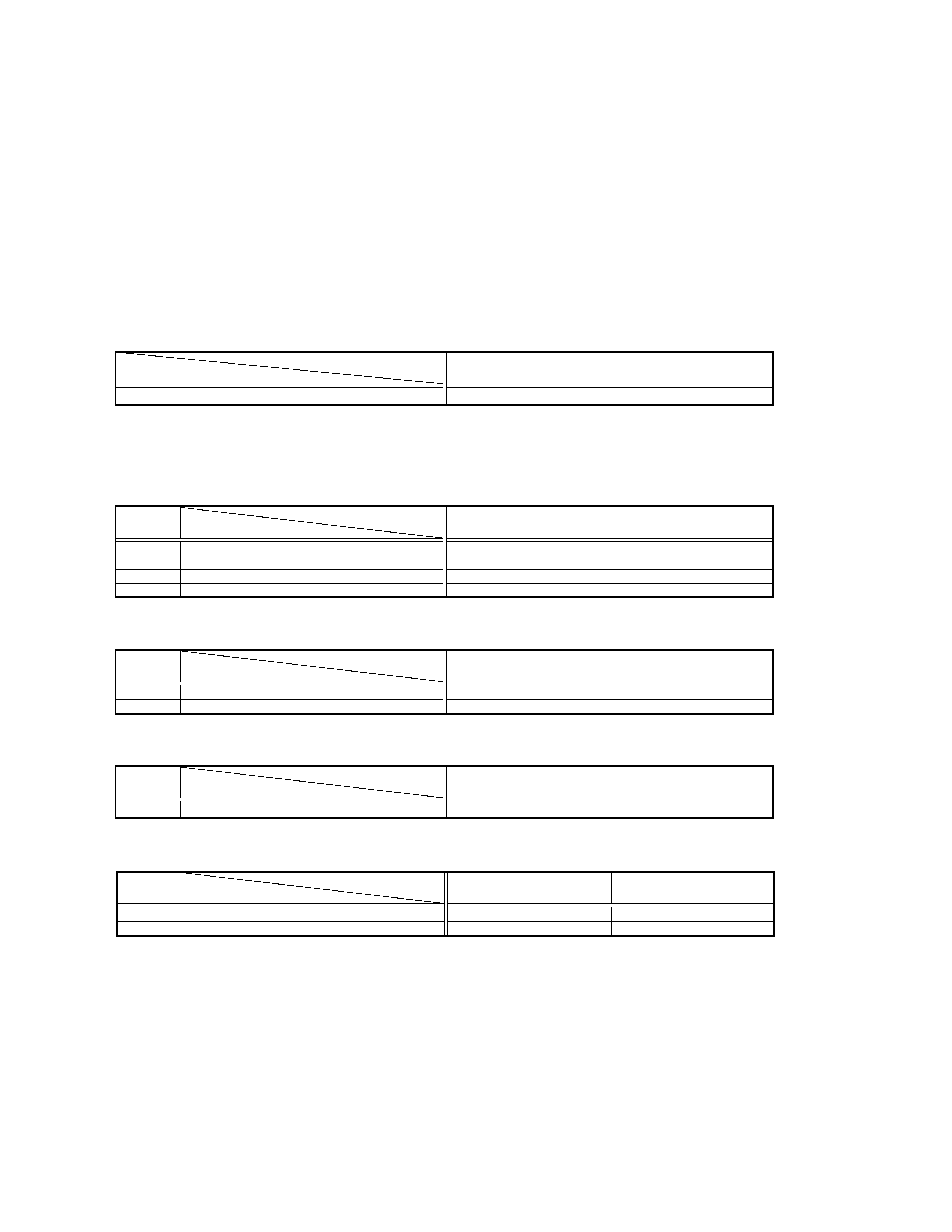
TABLE OF CONTENTS
DIFFERENT TABLE ........................................................................................................................................................................................... 1
5.
PARTS LIST (5-1 to 5-2)
5.1
PACKING AND ACCESSORY ASSEMBLY <M1> ................................................................................................................................ 5-1
REF.
MODEL
GR-DVL145EG-X
GR-DVL120A
!
NO.
ITEM
PACKING AND ACCESSORY ASSEMBLY <M1> Note: As for IB (INSTRUCTIONS), refer to sec.5.
The following table indicate different parts number between models GR-DVL145EG-X and GR-DVL120A.
9
WARRANTY CARD
BT-54013-2
--
13
SHEET(CON PLUG)
--
LYT0609-001A
! 29
CONVERSION PLUG
--
PEMC1012-02
35
ADAPTER PLUG
QAM0302-001
--
REF.
MODEL
GR-DVL145EG-X
GR-DVL120A
!
NO.
ITEM
FINAL ASSEMBLY <M2>
101
UPPER CASE ASSY
LY20867-002A
*LY20867-002B
116
STICKER(MONI.)
LY43808-002A
LY43808-003A
REF.
MODEL
GR-DVL145EG-X
GR-DVL120A
!
NO.
ITEM
MONITOR ASSEMBLY <M5>
519
DIFFUSION SHEET(2.5)
LY43362-001A
*LY43901-001A
REF.
MODEL
GR-DVL145EG-X
GR-DVL120A
!
NO.
ITEM
MAIN BOARD ASSEMBLY <01>
PW
MAIN BOARD ASSY
YB10368B-01
YB10368C
IC1401
IC(MICRO C ROM)
UPD703040YF-M12
UPD703040YF-M10
Notes : Mark -- is not used.
Mark * reference model was also changed.
1
MODEL
GR-DVL145EG-X
GR-DVL120A
ITEM
The following table indicate main different points between models GR-DVL145EG-X and GR-DVL120A.
DV TERMINAL
OUTPUT ONLY
IN/OUT

Printed in Japan
VICTOR COMPANY OF JAPAN, LIMITED
VIDEO DIVISION
S40894
SERVICE MANUAL
No. 86693
April 2002
SPECIFICATIONS
DIGITAL VIDEO CAMERA
Printed in Japan
This service manual is printed on 100% recycled paper.
COPYRIGHT © 2002 VICTOR COMPANY OF JAPAN, LTD.
GR-DVL145EG
No.
86693
GR-DVL145EG
VICTOR COMPANY OF JAPAN, LIMITED
VIDEO DIVISION
S40894
(The specifications shown pertain specifically to the model GR-DVL145EG/EK)
Camcorder
General
Power supply
: DC 11.0 V
(Using AC Adapter)
DC 7.2 V
(Using battery pack)
Power consumption
LCD monitor off, viewfinder on
: Approx. 4.3 W
LCD monitor on, viewfinder off
: Approx. 5.3 W
Dimensions (W x H x D)
: 83 mm x 94 mm x 223 mm
(with the LCD monitor closed and the viewfinder
pushed down)
Weight
: Approx. 630 g
Operating temperature
: 0°C to 40°C
Operating humidity
: 35% to 80%
Storage temperature
: 20°C to 50°C
Pickup
: 1/4" CCD
Lens
: F 1.6, f = 3.9 mm to 62.4 mm, 16:1 power zoom lens
Filter diameter
: ø40.5 mm
LCD monitor
: 2.5" diagonally measured, LCD panel/TFT active
matrix system
Viewfinder
: Electronic viewfinder with 0.24" black/white LCD
Speaker
: Monaural
Digital Video Camera
Format
: DV format (SD mode)
Signal format
: PAL standard
Recording/Playback format
: Video: Digital component recording
: Audio: PCM digital recording, 32 kHz 4-channel
(12-bit), 48 kHz 2-channel (16-bit)
Cassette
: Mini DV cassette
Tape speed
: SP: 18.8 mm/s
LP: 12.5 mm/s
Maximum recording time
: SP: 80 min.
(using 80 min. cassette)
LP: 120 min.
Connectors
S-Video
Output
: Y: 1 V (p-p), 75
, analogue
C: 0.29 V (p-p), 75
, analogue
AV
Video output
: 1 V (p-p), 75
, analogue
Audio output
: 300 mV (rms), 1 k
, analogue, stereo
DV
Output
: 4-pin, IEEE 1394 compliant
AC Adapter
Power requirement
: AC 110 V to 240 V`, 50 Hz/60 Hz
Output
: DC 11 V
, 1 A
Specifications shown are for SP mode unless otherwise indicated. E & O.E.
Design and specifications subject to change without notice.

Important Safety Precautions
INSTRUCTIONS
1. DISASSEMBLY
1.1 BEFORE ASSEMBLY AND DISASSEMBLY ......................... 1-1
1.1.1 Precautions ..................................................................... 1-1
1.1.2 Assembly and disassembly ............................................ 1-1
1.1.3 Destination of connectors ............................................... 1-1
1.1.4 Disconnection of connectors (Wires) .............................. 1-1
1.2 JIGS AND TOOLS REQUIRED FOR DISASSEMBLY,
ASSEMBLY AND ADJUSTMENT ......................................... 1-2
1.2.1 Tools required for adjustments ........................................ 1-2
1.3 DISASSEMBLY/ASSEMBLY OF CABINET PARTS AND
BOARD ASSEMBLY ............................................................. 1-2
1.3.1 Disassembly flow chart ................................................... 1-2
1.3.2 Disassembly method ...................................................... 1-3
1.4 $ MONITOR ASSEMBLY ..................................................... 1-9
1.4.1 Disassembly/assembly of monitor assembly (for 2.5"-type LCD) . 1-9
1.4.2 Disassembly/assembly of hinge assembly (for 2.5"-type LCD) . 1-9
1.5 # E. VF ASSEMBLY (B/W) ................................................. 1-10
1.5.1 Disassembly/assembly of E.VF ASSEMBLY (for the B/W VF) .. 1-10
1.6 DISASSEMBLY/ASSEMBLY OF 5OP BLOCK ASSEMBLY/
CCD BOARD ASSEMBLY ................................................... 1-11
1.6.1 Precautions ................................................................... 1-11
1.6.2 How to remove CCD board assembly and
CCD base assembly ..................................................... 1-11
1.6.3 How to assemble CCD base assembly and
CCD board assembly .................................................... 1-11
1.6.4 Replacement of Service Repair Parts .......................... 1-11
1.7 EMERGENCY DISPLAY ..................................................... 1-12
1.8 SERVICE NOTE .................................................................. 1-13
2. MECHANISM ADJUSTMENT
2.1 PRELIMINARY REMARKS ON ADJUSTMENT AND REPAIR .. 2-1
2.1.1 Precautions ..................................................................... 2-1
2.1.2 Notes on procedure for disassemby/assembly ............... 2-1
2.2 JIGS AND TOOLS REQUIRED FOR DISASSEMBLY,
ASSEMBLY AND ADJUSTMENT ......................................... 2-2
2.2.1 Tools required for adjustments ........................................ 2-2
2.3 DISASSEMBLY/ASSEMBLY OF MECHANISM ASSEMBLY 2-3
2.3.1 General statement .......................................................... 2-3
2.3.2 Explanation of mechanism mode ................................... 2-3
2.3.3 Mechanism timing chart .................................................. 2-4
2.4 DISASSEMBLY/ASSEMBLY OF MECHANISM ASSEMBLY 2-5
2.4.1 Follow chart .................................................................... 2-5
2.4.2 Disassembly/assembly ................................................... 2-8
2.4.3 List of procedures for disassembly ............................... 2-14
2.5 CHECKUP AND ADJUSTMENT OF MECHANISM PHASE .... 2-15
2.6 MECHANISM ADJUSTMENTS .......................................... 2-16
2.6.1 Assembling slide deck assembly and main deck assembly . 2-16
2.6.2 Locating tension pole .................................................... 2-17
2.7 SERVICE NOTE .................................................................. 2-18
2.8 COMPATIBILITY ADJUSTMENT ........................................ 2-20
2.8.1 Jig connector cable connection .................................... 2-20
2.8.2 Tape pattern check ....................................................... 2-21
TABLE OF CONTENTS
Section
Title
Page
Section
Title
Page
3. ELECTRICAL ADJUSTMENT
3.1 PRECAUTION ....................................................................... 3-1
3.2 SETUP .................................................................................. 3-2
4. CHARTS AND DIAGRAMS
NOTES OF SCHEMATIC DIAGRAM .......................................... 4-1
CIRCUIT BOARD NOTES ........................................................... 4-2
4.1 BOARD INTERCONNECTIONS ........................................... 4-3
4.2 MAIN IF SCHEMATIC DIAGRAM ............................................... 4-5
4.3 SYSCON SCHEMATIC DIAGRAM ............................................. 4-7
4.4 D.CPU SCHEMATIC DIAGRAM ................................................. 4-9
4.5 MDA SCHEMATIC DIAGRAM .................................................. 4-11
4.6 AUDIO SCHEMATIC DIAGRAM ............................................... 4-13
4.7 DVMAIN SCHEMATIC DIAGRAM ............................................ 4-15
4.8 PRE/REC SCHEMATIC DIAGRAM .......................................... 4-17
4.9 V OUT SCHEMATIC DIAGRAM ............................................... 4-19
4.10 DSP SCHEMATIC DIAGRAM ................................................ 4-21
4.11 MONI IF SCHEMATIC DIAGRAM .......................................... 4-23
4.12 OP.DRV SCHEMATIC DIAGRAM .......................................... 4-25
4.13 TG SCHEMATIC DIAGRAM ................................................... 4-27
4.14 REG SCHEMATIC DIAGRAM ................................................ 4-29
4.15 MONITOR SCHEMATIC DIAGRAM ....................................... 4-31
4.16 LCD BL SCHEMATIC DIAGRAM ........................................... 4-33
4.17 CCD SCHEMATIC DIAGRAM ................................................ 4-35
4.18 JUNCTION SCHEMATIC DIAGRAM ..................................... 4-36
4.19 JACK SCHEMATIC DIAGRAM .............................................. 4-37
4.20 B/W VF SCHEMATIC DIAGRAM ........................................... 4-39
4.21 MAIN CIRCUIT BOARD ......................................................... 4-41
4.22 MONITOR CIRCUIT BOARD ................................................. 4-47
4.23 LCD BL CIRCUIT BOARD ...................................................... 4-49
4.24 CCD, VF AND JUNCTION CIRCUIT BOARDS ..................... 4-51
4.25 JACK CIRCUIT BOARD ......................................................... 4-53
4.26 VOLTAGE CHARTS ............................................................... 4-55
4.27 POWER SYSTEM BLOCK DIAGRAM ................................... 4-57
4.28 VIDEO SYSTEM BLOCK DIAGRAM ...................................... 4-59
4.29 REGULATOR SYSTEM BLOCK DIAGRAM .......................... 4-63
5. PARTS LIST
5.1 PACKING AND ACCESSORY ASSEMBLY <M1> ............... 5-1
5.2 FINAL ASSEMBLY <M2> ..................................................... 5-3
5.3 MECHANISM ASSEMBLY <M3> ......................................... 5-6
5.4 ELECTRONIC VIEWFINDER ASSEMBLY <M4> ................ 5-8
5.5 MONITOR ASSEMBLY <M5> .............................................. 5-9
5.6 ELECTRICAL PARTS LIST ................................................. 5-10
MAIN BOARD ASSEMBLY <01> ........................................... 5-10
MONITOR BOARD ASSEMBLY <02> .................................... 5-17
LCD BL BOARD ASSEMBLY <03> ........................................ 5-18
CCD BOARD ASSEMBLY <04> ............................................. 5-19
JUNCTION BOARD ASSEMBLY <05> .................................. 5-19
JACK BOARD ASSEMBLY <06> ........................................... 5-19
B/W VF BOARD ASSEMBLY <08> ........................................ 5-19