SERVICE MANUAL
No.86596
January 2001
GR-AX760U,AX761U,SX860U
COMPACT VHS CAMCORDER
SPECIFICATIONS
Connectors
Video
: 1 V (p-p), 75 unbalanced,
analog output
(via Video output connector)
AC Adapter AP-V10U
Power requirement
U.S.A. and Canada : AC 120 V`, 60 Hz
Other countries
: AC 110 V to 240 V`,
50 Hz/60 Hz
Output
: DC 11 V
, 1 A
Dimensions
: 59 mm x 31 mm x 69 mm
(W x H x D)
(2-3/8" x 1-1/4" x 2-3/4")
Weight
: Approx. 130 g (0.29 lbs)
Optional Accessories
· Battery Packs BN-V12U, BN-V20U, BN-V400U
· A/V (Audio/Video) Cable
· S-Video Cable QAM0004-004
· Compact S-VHS (
) Cassettes ST-C-40/30/20
· Compact VHS (
) Cassettes TC-40/30/20
· Active Carrying Bag CB-V7U
Camcorder
General
Format
: S-VHS (GR-SXM330/SX860
only)/VHS NTSC standard
Power source
: DC 11 V
(Using AC Adapter)
DC 6 V
(Using battery pack)
Power consumption
Viewfinder on
: 4.0 W (GR-SXM330/AXM230
only)
3.7 W (GR-SX860/AX760 only)
LCD monitor* on
: 4.5 W (GR-SXM330/AXM230
only)
Video light**
: 3.0 W
* Models equipped with LCD monitor only.
** GR-SXM330/AXM230 only.
Signal system
: NTSC-type
Video recording system
Luminance
: FM recording
Color
: Converted sub-carrier
direct recording
Conforms to VHS standard
Cassette
:
/
cassette
Tape speed
SP
: 33.35 mm/sec. (1-5/16 ips)
EP
: 11.12 mm/sec. (7/16 ips)
Recording time (max.)
SP
: 40 minutes
EP
: 120 minutes (with TC-40)
Operating
temperature
:0
°C to 40°C (32°F to 104°F)
Operating humidity
: 35% to 80%
Storage temperature
: 20
°C to 50°C
(4
°F to 122°F)
Weight
: Approx. 900 g (2.0 lbs)
(GR-SXM330/AXM230 only)
Approx. 720 g (1.6 lbs)
(GR-SX860/AX760 only)
Some accessories are not available in some areas. Please
consult your nearest JVC dealer for details on accessories
and their availability.
Specifications shown are for SP mode unless otherwise indicated. E & O.E. Design and specifications subject to change
without notice.
Dimensions
: 206 mm x 112 mm x 118 mm
(W x H x D)
(8-1/8" x 4-7/16" x 4-11/16")
(GR-SXM330/AXM230 only)
206 mm x 112 mm x 115 mm
(8-1/8" x 4-7/16" x 4-9/16")
(GR-SX860/AX760 only)
* Models equipped with LCD monitor only.
Pickup
: 1/4" format CCD
Lens
: F1.6, f = 3.9 mm to 62.4 mm,
16:1 power zoom lens with
auto iris and macro control,
filter diameter 40.5 mm
Viewfinder
: Electronic viewfinder with
0.55" color LCD
(GR-SX860 only)
Electronic viewfinder with 0.5"
black/white CRT
(GR-SXM330/AXM230/AX760
only)
White balance
adjustment
: Auto/Manual adjustment
LCD monitor
: 2.5" diagonally measured, LCD
panel/TFT active matrix system
Speaker
: Monaural
(models equipped with
LCD monitor only)
(models equipped with
LCD monitor only)
Audio
: 300 mV (rms), 1 k
analog
output
(via Audio output connector)
S-Video
: Y : 1 V (p-p), 75 ,
analog output
C : 0.29 V (p-p), 75 ,
analog output
(GR-SXM330/SX860
only)
(The specifications shown pertain specifically to the model GR-AX760U,SX860U)
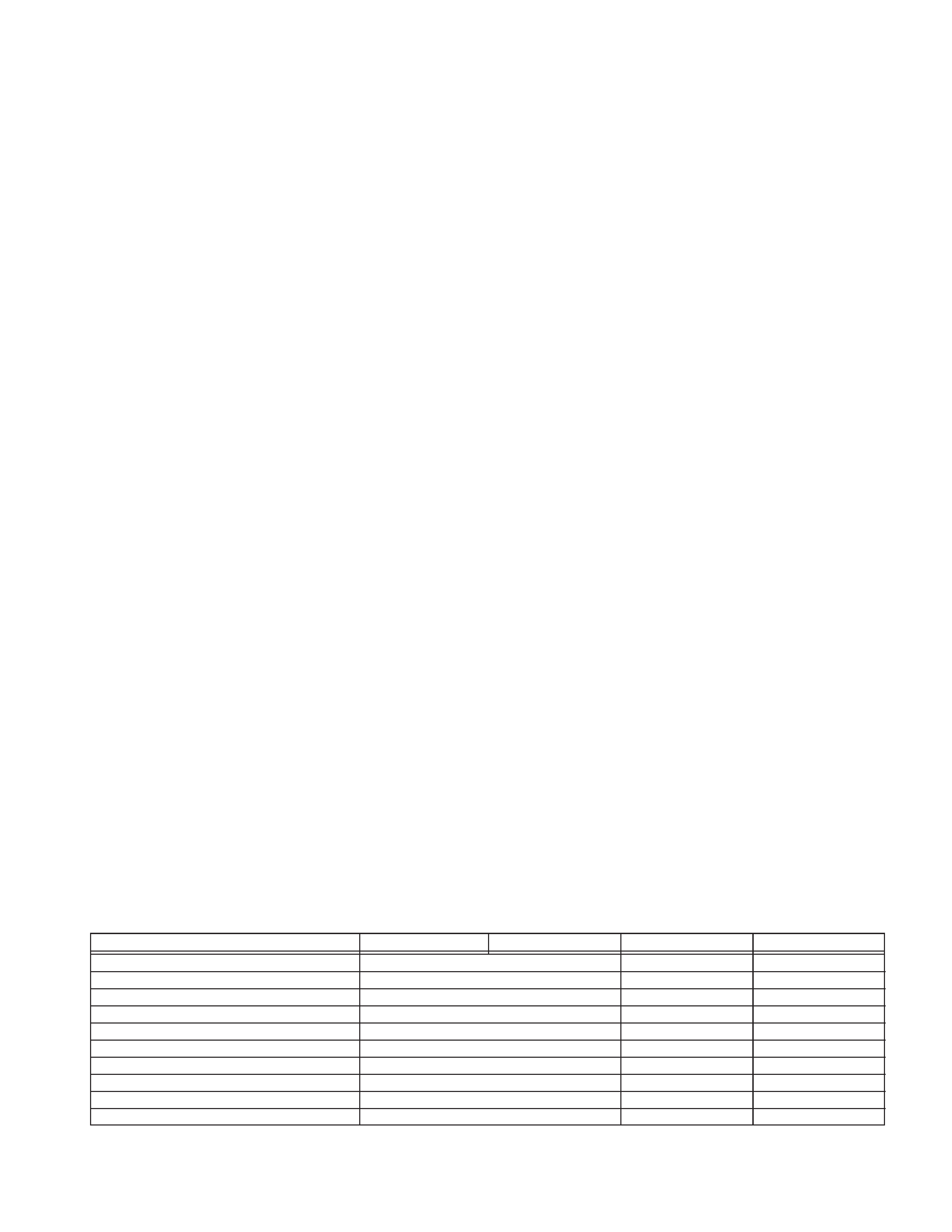
TABLE OF CONTENTS
Section
Title
Page
Important Safety Precautions
INSTRUCTIONS
1. DISASSEMBLY
1.1
SERVICE CAUTIONS .......................................................... 1-1
1.1.1
Precautions .................................................................. 1-1
1.1.2
How to read the disassembly and assembly ................ 1-1
1.1.3
Connection of the wires ................................................ 1-1
1.2
TOOLS REQUIRED FOR ADJUSTMENTS ......................... 1-2
1.3
DISASSEMBLY/ASSEMBLY OF CABINET PARTS ............. 1-3
1.3.1
Disassembly flow chart ................................................. 1-3
1.3.2
Disassembly method .................................................... 1-4
1.4
DISASSEMBLY/ASSEMBLY OF CAMERA SECTION
AND DECK SECTION .......................................................... 1-8
1.4.1
Flowchart of disassembly ............................................. 1-8
1.4.2
Disassembly method .................................................... 1-8
1.5
REPLACEMENT OF CCD IMAGE SENSOR ..................... 1-10
1.5.1
Removal of CCD image sensor .................................. 1-10
1.5.2
Installation of new CCD image sensor ....................... 1-10
1.5.3
Replacement of CCD board assy ............................... 1-10
1.6
TAKE OUT CASSETTE TAPE ............................................ 1-11
1.7
EMERGENCY DISPLAY ..................................................... 1-12
1.8
DEMONSTRATION MODE ................................................ 1-12
1.9
SERVICE NOTE ................................................................. 1-14
2. MECHANISM ADJUSTMENT
2.1
Required adjustment tools ...................................................... 2-1
3. ELECTRICAL ADJUSTMENT
3.1
ELECTRICAL ADJUSTMENT ............................................... 3-1
3.1.1
PREPARATION ............................................................ 3-1
3.2
ELECTRONIC VIEWFINDER (E.VF) ADJUSTMENT .......... 3-3
3.2.1
Tilt ................................................................................. 3-3
3.2.2
Centering ...................................................................... 3-3
3.2.3
Vertical Scanning ......................................................... 3-3
3.2.4
Brightness .................................................................... 3-3
3.2.5
Foucs ............................................................................ 3-3
4. CHARTS AND DIAGRAMS
NOTES OF SCHEMATIC DIAGRAM ................................... 4-1
CIRCUIT BOARD NOTES .................................................... 4-2
4.1
BOARD INTERCONNECTIONS .......................................... 4-3
4.2
CPU SCHEMATIC DIAGRAM .............................................. 4-5
4.3
VTR ASP SCHEMATIC DIAGRAM ....................................... 4-7
4.4
MECHA MDA SCHEMATIC DIAGRAM ................................ 4-9
4.5
VTR DSP SCHEMATIC DIAGRAM .................................... 4-11
4.6
DSP SCHEMATIC DIAGRAM ............................................. 4-13
4.7
IRIS & AF/ZOOM SCHEMATIC DIAGRAM ........................ 4-15
4.8
VIDEO OUT SCHEMATIC DIAGRAM ................................ 4-17
4.9
REGULATOR SCHEMATIC DIAGRAM .............................. 4-19
4.10 LCD CTL SCHEMATIC DIAGRAM (FOR AX760U/UC) ....... 4-21
4.11 LCD CTL SCHEMATIC DIAGRAM (FOR AX761U,SX860U) ........ 4-23
4.12 JACK AND CCD SCHEMATIC DIAGRAM ......................... 4-25
4.13 C-VF BL SENSOR SCHEMATIC DIAGRAM
(FOR AX761U,SX860U) .................................................... 4-27
4.14 TOP OPE UNIT, ZOOM UNIT, REAR UNIT
AND SENSOR SCHEMATIC DIAGRAM .............................. 4-29
4.15 ELECTRONIC VIEWFINDER SCHEMATIC DIAGRAM
(FOR AX760U/UC) ............................................................. 4-31
4.16 MAIN CIRCUIT BOARD ..................................................... 4-33
4.17 CCD AND C-VF CIRCUIT BOARDS .................................. 4-39
4.18 ELECTRONIC VIEWFINDER CIRCUIT BOARD ............... 4-41
4.19 POWER SYSTEM BLOCK DIAGRAM ............................... 4-43
4.20 CPU/MDA SYSTEM BLOCK DIAGRAM ............................ 4-45
4.21 CAMERA SYSTEM BLOCK DIAGRAM .............................. 4-47
4.22 Y/C SYSTEM BLOCK DIAGRAM ....................................... 4-51
4.23 MONITOR SYSTEM BLOCK DIAGRAM ............................ 4-53
4.24 WAVEFORMS .................................................................... 4-55
4.25 VOLTAGE CHARTS ........................................................... 4-56
5. PARTS LIST
5.1
PACKING AND ACCESSORY ASSEMBLY <M1> ................ 5-1
5.2
FINAL ASSEMBLY <M2> ..................................................... 5-3
5.3
MECHANISM ASSEMBLY <M3> .......................................... 5-6
5.4
ELECTRONIC VIEWFINDER ASSEMBLY <M4> ................. 5-8
5.5
ELECTRICAL PARTS LIST ................................................ 5-10
MAIN BOARD ASSEMBLY <01> ........................................ 5-10
CCD BOARD ASSEMBLY <02> ......................................... 5-16
C-VF BL BOARD ASSEMBLY <06> ................................... 5-16
Section
Title
Page
The following table lists the differing points between Models GR-AX760U/UC and GR-AX761U,GR-SX860U in this series.
GR-AX760U
GR-AX760UC
GR-AX761U
GR-SX860U
VIDEO LIGHT
NOT USED
USED
NOT USED
IR RECEIVER
NOT USED
USED
NOT USED
TAPE FORMAT
VHS-C
+
S-VHS-C
S-VHS ON/OFF
NOT USED
+
USED
S-VHS ET
NOT USED
+
USED
S-VHS ET ON/OFF
NOT USED
+
USED
S OUT PUT
NOT USED
+
USED
LIGHT SW
NOT USED
USED
NOT USED
VIEW FINDER
B/W
COLOR
+
REMOTE CONTROL UNIT
NOT USED
USED
NOT USED
Note: Mark
+ is same as left.
Important Safety Precautions
Prior to shipment from the factory, JVC products are strictly inspected to conform with the recognized product safety and electrical codes
of the countries in which they are to be sold. However, in order to maintain such compliance, it is equally important to implement the
following precautions when a set is being serviced.
Fig.1
1. Locations requiring special caution are denoted by labels and
inscriptions on the cabinet, chassis and certain parts of the
product. When performing service, be sure to read and com-
ply with these and other cautionary notices appearing in the
operation and service manuals.
2. Parts identified by the
symbol and shaded (
) parts are
critical for safety.
Replace only with specified part numbers.
Note: Parts in this category also include those specified to com-
ply with X-ray emission standards for products using
cathode ray tubes and those specified for compliance
with various regulations regarding spurious radiation
emission.
3. Fuse replacement caution notice.
Caution for continued protection against fire hazard.
Replace only with same type and rated fuse(s) as specified.
4. Use specified internal wiring. Note especially:
1) Wires covered with PVC tubing
2) Double insulated wires
3) High voltage leads
5. Use specified insulating materials for hazardous live parts.
Note especially:
1) Insulation Tape
3) Spacers
5) Barrier
2) PVC tubing
4) Insulation sheets for transistors
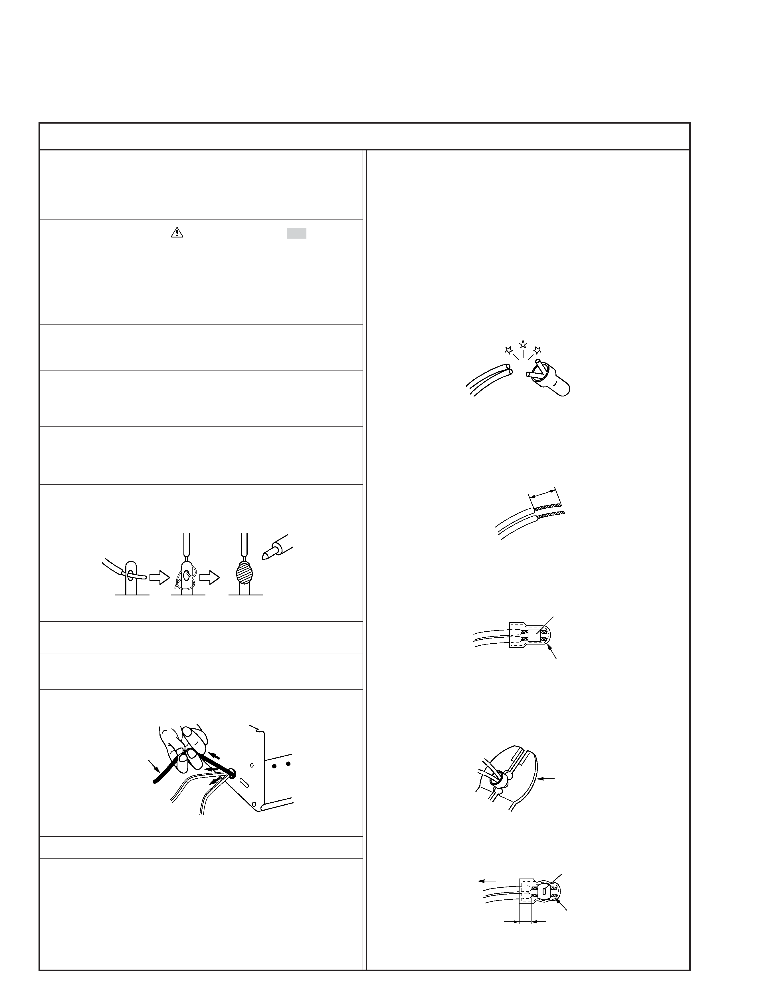
6. When replacing AC primary side components (transformers,
power cords, noise blocking capacitors, etc.) wrap ends of
wires securely about the terminals before soldering.
Power cord
Fig.2
10. Also check areas surrounding repaired locations.
11. Products using cathode ray tubes (CRTs)
In regard to such products, the cathode ray tubes themselves,
the high voltage circuits, and related circuits are specified for
compliance with recognized codes pertaining to X-ray emission.
Consequently, when servicing these products, replace the cath-
ode ray tubes and other parts with only the specified parts.
Under no circumstances attempt to modify these circuits.
Unauthorized modification can increase the high voltage value
and cause X-ray emission from the cathode ray tube.
12. Crimp type wire connector
In such cases as when replacing the power transformer in sets
where the connections between the power cord and power
transformer primary lead wires are performed using crimp type
connectors, if replacing the connectors is unavoidable, in or-
der to prevent safety hazards, perform carefully and precisely
according to the following steps.
1) Connector part number : E03830-001
2) Required tool : Connector crimping tool of the proper type
which will not damage insulated parts.
3) Replacement procedure
(1) Remove the old connector by cutting the wires at a point
close to the connector.
Important : Do not reuse a connector (discard it).
Fig.7
cut close to connector
Fig.3
(2) Strip about 15 mm of the insulation from the ends of
the wires. If the wires are stranded, twist the strands to
avoid frayed conductors.
15 mm
Fig.4
(3) Align the lengths of the wires to be connected. Insert
the wires fully into the connector.
Connector
Metal sleeve
Fig.5
(4) As shown in Fig.6, use the crimping tool to crimp the
metal sleeve at the center position. Be sure to crimp fully
to the complete closure of the tool.
1
Precautions during Servicing
7. Observe that wires do not contact heat producing parts
(heatsinks, oxide metal film resistors, fusible resistors, etc.)
8. Check that replaced wires do not contact sharp edged or
pointed parts.
9. When a power cord has been replaced, check that 10-15 kg of
force in any direction will not loosen it.
1.25
2.0
5.5
Crimping tool
Fig.6
(5) Check the four points noted in Fig.7.
Not easily pulled free
Crimped at approx. center
of metal sleeve
Conductors extended
Wire insulation recessed
more than 4 mm
S40888-01
Safety Check after Servicing
Examine the area surrounding the repaired location for damage or deterioration. Observe that screws, parts and wires have been
returned to original positions, Afterwards, perform the following tests and confirm the specified values in order to verify compli-
ance with safety standards.
1. Insulation resistance test
Confirm the specified insulation resistance or greater between power cord plug prongs and
externally exposed parts of the set (RF terminals, antenna terminals, video and audio input
and output terminals, microphone jacks, earphone jacks, etc.). See table 1 below.
2. Dielectric strength test
Confirm specified dielectric strength or greater between power cord plug prongs and exposed
accessible parts of the set (RF terminals, antenna terminals, video and audio input and output
terminals, microphone jacks, earphone jacks, etc.). See table 1 below.
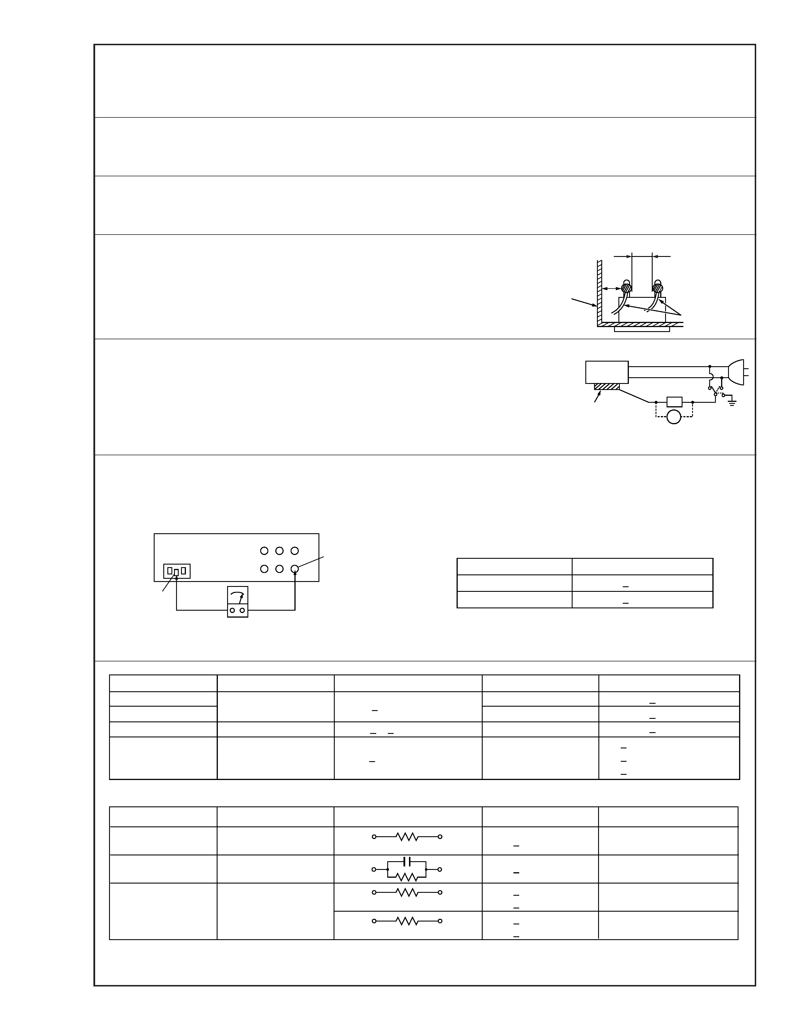
3. Clearance distance
When replacing primary circuit components, confirm specified clearance distance (d), (d') be-
tween soldered terminals, and between terminals and surrounding metallic parts. See table 1
below.
4. Leakage current test
Confirm specified or lower leakage current between earth ground/power cord plug prongs
and externally exposed accessible parts (RF terminals, antenna terminals, video and audio
input and output terminals, microphone jacks, earphone jacks, etc.).
Measuring Method : (Power ON)
Insert load Z between earth ground/power cord plug prongs and externally exposed accessi-
ble parts. Use an AC voltmeter to measure across both terminals of load Z. See figure 9 and
following table 2.
5. Grounding (Class 1 model only)
Confirm specified or lower grounding impedance between earth pin in AC inlet and externally exposed accessible parts (Video in,
Video out, Audio in, Audio out or Fixing screw etc.).
Measuring Method:
Connect milli ohm meter between earth pin in AC inlet and exposed accessible parts. See figure 10 and grounding specifications.
d'
d
Chassis
Power cord,
primary wire
Region
USA & Canada
Europe & Australia
Grounding Impedance (Z)
Z
0.1 ohm
Z
0.5 ohm
AC inlet
Earth pin
Exposed accessible part
Milli ohm meter
Grounding Specifications
Fig. 10
ab
c
V
Externally
exposed
accessible part
Z
Fig. 9
Fig. 8
Clearance Distance (d), (d')
d, d'
3 mm
d, d'
4 mm
d, d'
3.2 mm
1 M
R 12 M/500 V DC
Dielectric Strength
AC 1 kV 1 minute
AC 1.5 kV 1 miute
AC 1 kV 1 minute
AC Line Voltage
100 V
100 to 240 V
110 to 130 V
110 to 130 V
200 to 240 V
Japan
USA & Canada
Europe & Australia
R
10 M
/500 V DC
Region
Insulation Resistance (R)
R
1 M
/500 V DC
AC 3 kV 1 minute
(Class
2)
AC 1.5 kV 1 minute
(Class
1)
d
4 mm
d'
8 mm (Power cord)
d'
6 mm (Primary wire)
Table 1 Specifications for each region
a, b, c
Leakage Current (i)
AC Line Voltage
100 V
110 to 130 V
110 to 130 V
220 to 240 V
Japan
USA & Canada
i
1 mA rms
Exposed accessible parts
Exposed accessible parts
Antenna earth terminals
Other terminals
i
0.5 mA rms
i
0.7 mA peak
i
2 mA dc
i
0.7 mA peak
i
2 mA dc
Europe & Australia
Region
Load Z
1 k
2 k
1.5 k
0.15
µF
50 k
Table 2 Leakage current specifications for each region
Note: These tables are unofficial and for reference only. Be sure to confirm the precise values for your particular country and locality.
2
S40888-01

1-1
(1) Order of steps in Procedure
When reassembling, preform the step(s) in the reverse
order. These numbers are also used as the identifica-
tion (location) No. of parts Figures.
(2) Part to be removed or installed.
(3) Fig. No. showing Procedure or Part Location.
C = Cabinet
CA = Camera
D = Deck
(4) Identification of part to be removed, unhooked, unlocked,
released, unplugged, unclamped or unsoldered.
P = Spring
W = Washer
S = Screw
* = Unhook, unlock, release, unplug or unsolder.
2(S3) = 2 Screws (S3)
CN = Connector
(5) Adjustment information for installation.
1
CASSETTE
C1
(S1),3(L1a),(L1b),(L1c)
COVER ASSEMBLY
Push button, spring
2
UPPER CASE
C2
2(S2), (L2)
LOWER CASE
C3
9(S3), (L3a), (L3b)
3
ASSEMBLY(INCL.
*CN 3a 3b
E. VF. ASSEMBLY)
CAP (RCA jack)
SECTION 1
DISASSEMBLY
1.1 SERVICE CAUTIONS
1.1.1
Precautions
1. Before disassembling/re-assembling the set as well as
soldering parts, make sure to disconnect the power
cable.
2. When disconnecting/connecting connectors, pay enough
attention to wiring not to damage it.
3. In general, chip parts such as resistor, shorting jumpers
(0-ohm resistor), ceramic capacitors, diodes, etc. can not
be reused after they were once removed.
4. When installing parts, be careful not to do with other parts
as well as not to damage others.
5. When removing ICs, be careful not to damage circuit
patterns.
6. Tighten screws properly during the procedures. Unless
specified otherwise, tighten screws at torque of 0.196 N·m
(2.0 kgf·cm).
1.1.2
How to read the disassembly and assembly
STEP
/LOC
PART
NO.
REMOVAL
(For Cabinet Parts)
Fig.
No.
1.1.3
Connection of the wires
1. Pull the connector structure upward to release the clamp
when removing or inserting the flat wire cable.
Fig. 1-1-1
Connector
Wire
Connector
Wire
Fig. 1-1-2
NOTE:
After removing the wire, return the stopper to
its original position, because it is apt to come
off if it is left open.
*UNLOCK/RELEASE/
UNPLUG/UNCLAMP/
UNSOLDER
(1)
(2)
(3)
(4)
v
v
v
v