INSTRUCTIONS
DT-V1900CG
MULTI-FORMAT MONITOR
VOLUME
SLOT1
A
B
DEGAUSS
MENU
MUTING
SCREENS
CHECK
ASPECT
AREA
MARKER
UNDER
SCAN
PULSE
CROSS
COLOR
OFF
SLOT2
C
D
SLOT3
POWER
E
F
INPUT SELECT
For Customer Use:
Enter below the Serial No. which is located on the rear of
the cabinet. Retain this information for future reference.
Model No.
:
DT-V1900CG
Serial No.
:
The illustration above shows the DT-V1900CG with provided
wide mask attached.
LCT1117-001B
LCT1117-001B
02.2.12, 1:51 PM
1
2
FCC INFORMATION (U.S.A. only)
CAUTION: Changes or modification not approved by
JVC could void the user's authority to operate the
equipment.
NOTE: This equipment has been tested and found to
comply with the limits for a Class A digital device,
pursuant to Part 15 of the FCC Rules. These limits are
designed to provide reasonable protection against
harmful interference when the equipment is operated in a
commercial environment. This equipment generates,
uses, and can radiate radio frequency energy and, if not
installed and used in accordance with the instruction
manual, may cause harmful interference to radio
communications. Operation of this equipment in a
residential area is likely to cause harmful interference in
which case the user will be required to correct the
interference at his own expense.
SCREEN BURN
It is not recommended to keep a certain still image
displayed on screen for a long time as well as displaying
extremely bright images on screen. This may cause a
burning (sticking) phenomenon on the screen of cathode-ray
tube. This problem does not occur as far as displaying
normal video playback motion images.
PRECAUTIONS
Use only the power source specified on the unit.
(120 V/230 V AC, 50 Hz/60 Hz)
Keep flammable material, water, and metal objects away
from the unit especially the interior of the unit.
This unit incorporates high voltage circuitry.
For your own safety and that of your equipment, do not
attempt to modify or disassemble this monitor.
There are no user-serviceable parts inside.
Video or audio signals cannot be input to this monitor
without optional input cards.
In these instructions, all explanations (except where noted)
refer to the DT-V1900CG with input cards installed.
HANDLING
Avoid shocks or vibrations. These may damage the unit and
cause it to malfunction.
Do not block the ventilation slots.
Do not expose this unit to high temperatures.
Extended exposure to direct sunlight or a heater could
deform the cabinet or cause the performance of internal
components to deteriorate.
Do not place the unit near appliances generating strong
electric or magnetic fields. There can generate picture noise
and instability.
Keep the monitor clean by wiping the cabinet and CRT
screen with a piece of soft cloth. Do not apply thinner or
benzine. These chemicals can damage the finish and erase
printed letters. When the unit is excessively dirty, use a
diluted neutral cleanser, then wipe away the cleanser with a
dry cloth.
DEGAUSS
Do not use a magnet eraser to degauss the monitor's
cathode ray tube from the outside. Doing so may distort its
aperture grill and cause a malfunction.
In order to prevent any fatal accidents caused by
misoperation or mishandling the monitor, be fully aware of all
the following precautions.
WARNINGS
To prevent fire or shock hazard, do not expose this
monitor to rain or moisture. Dangerous high voltages
are present inside the unit. Do not remove the back
cover of the cabinet. When servicing the monitor,
consult qualified service personnel. Never try to service
it yourself.
WARNING : THIS APPARATUS
MUST BE EARTHED.
This monitor is equipped with a 3-blade grounding-type
plug to satisfy FCC rule. If you are unable to insert the
plug into the outlet, contact your electrician.
Improper operations, in particular alternation of high
voltage or changing the type of tube may result in x-ray
emission of considerable dose. A unit altered in such a
way no longer meets the standards of certification, and
must therefore no longer be operated.
Notice (U.S.A. only)
This product utilizes both a Cathode Ray Tube (CRT) and
other components that contain lead. Disposal of these
materials may be regulated in your community due to
environmental considerations. For disposal or recycling
information please contact your local authorities, or the
Electronics Industries Alliance: <http://www.eiae.org.>
SAFETY PRECAUTIONS
LCT1117-001A
02.1.29, 2:31 PM
2
3
SAFETY PRECAUTIONS ........................................................................ 2
CONTROLS AND FEATURES ................................................................ 4
CONTROLS AND FEATURES
(INPUT CARD: OPTIONAL) .................................................................. 6
PREPARATION ....................................................................................... 9
BASIC MENU OPERATIONS
(MAIN MENU, SETUP MENU) ............................................................ 11
HOW TO USE "MAIN MENU" ............................................................... 12
HOW TO USE "SETUP MENU" ............................................................ 15
HOW TO USE EXTERNAL CONTROL ................................................. 20
TROUBLESHOOTING........................................................................... 22
SELF-CHECK INDICATIONS .............................................................. 24
SPECIFICATIONS ................................................................................. 25
CONTENTS
Fuse
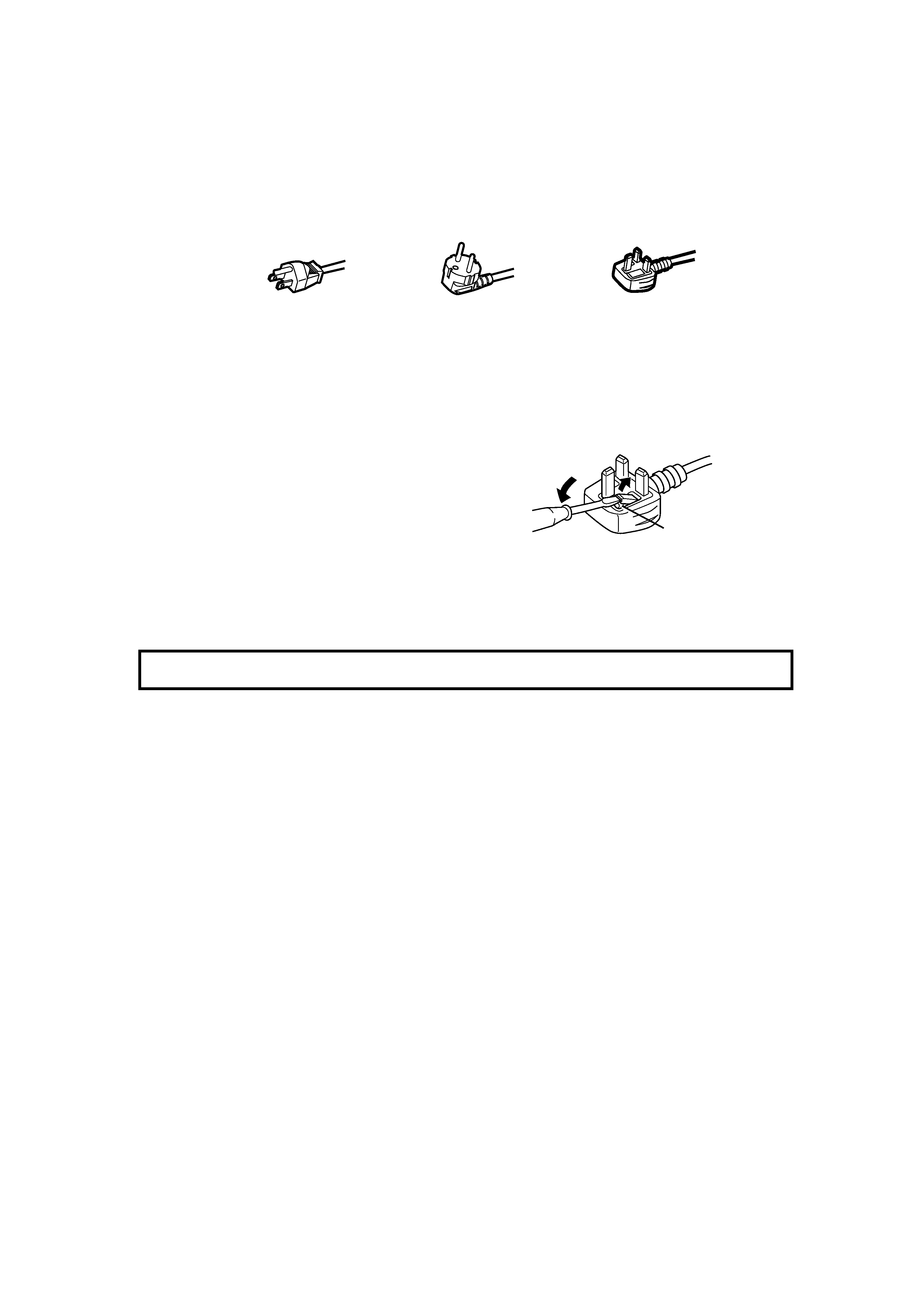
POWER CONNECTION
The power supply voltage rating of this product is AC 120 V (For U.S.A. and Canada only) and AC 230 V (For European countries
or United Kingdom), the power cord attached conforms to the following power supply voltage and countries. Use only the power
cord designated to ensure Safety and EMC regulations of each countries.
Power cord
Power supply voltage : AC 120 V
AC 230 V
AC 230 V
Countries
: U.S.A. and Canada
European countries
United Kingdom
Warning:
Do not use the same Power Cord for AC 120 V as for AC 230 V. Doing so may cause malfunction, electric shock
or fire.
Note for the United Kingdom power cord only
The plug on the United Kingdom power cord has a built-in fuse. When replacing the fuse, be sure to use only a correctly rated
approved type, re-fit the fuse cover.
(Consult your dealer or qualified service personnel.)
How to replace the fuse
Open the fuse compartment with the blade screw driver, and
replace the fuse.
(* An example is shown in the illustration.)
LCT1117-001A
02.1.29, 2:31 PM
3
4
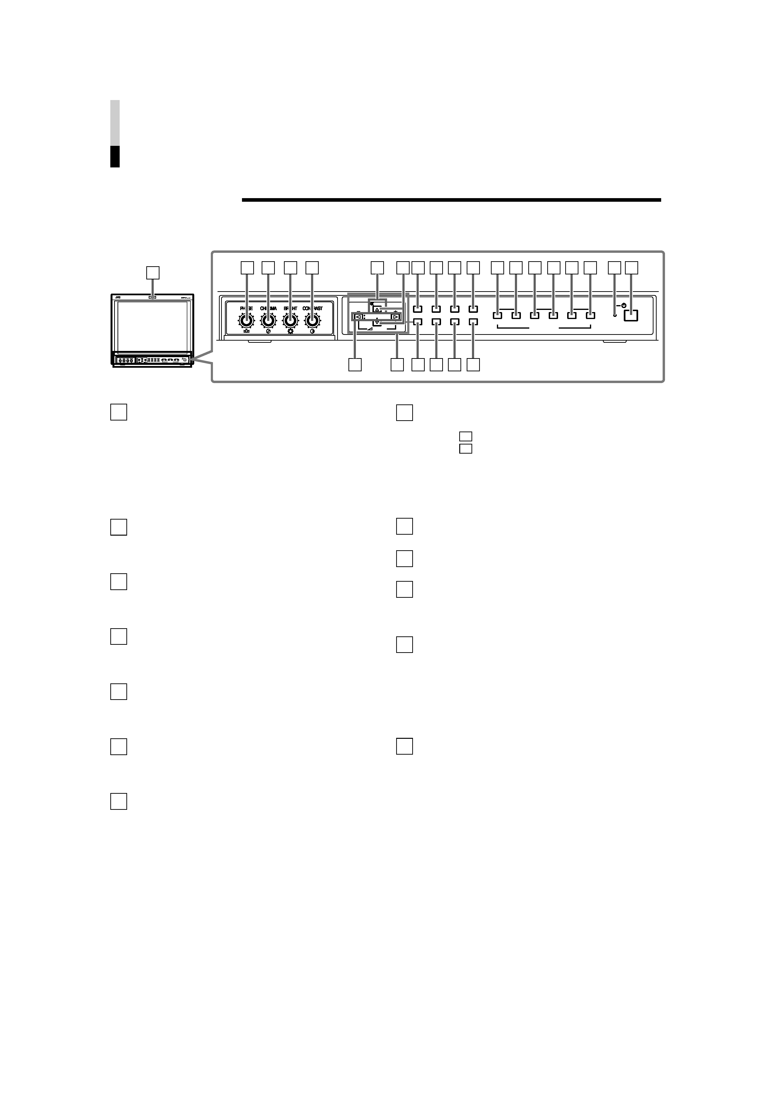
CONTROLS AND FEATURES
FRONT VIEW
<Front Panel>
Tally lamp
Lights when the tally control signal is ON. Set the MAKE/
TRIGGER terminal's tally control in the REMOTE
(external control) terminal setup menu. For details, refer
to Page 20. The lamp color can be set to red or green.
To set the color, use TALLY SELECT in the "FUNCTION
SETTING" setup menu or MAKE/TRIGGER in the
REMOTE (external control) terminal setup menu. For
details, refer to Page 16 and 20.
PHASE adjustment knob
Adjusts picture hue. Turn the knob to the left to make the
picture redder, and turn it to the right to make the picture
greener.
CHROMA adjustment knob
Adjusts picture color density. Turn the knob to the left to
make the picture color lighter, and turn it to the right to
make the picture color deeper.
BRIGHT adjustment knob
Adjusts picture brightness. Turn the knob to the left to
make the picture darker, and turn it to the right to make
the picture brighter.
CONTRAST adjustment knob
Adjusts picture contrast. Turn the knob to the left to make
the picture contrast lower, and turn it to the right to make
the picture contrast higher.
VOLUME buttons
Adjusts the speaker volume. Pressing this button displays
the VOLUME level bar on the screen. Pressing the
button again allows you to adjust speaker volume.
MUTING button
Pressing this button mutes the input sound. "MUTING
ON" is displayed on the screen. Pressing the VOLUME
"/+" button or the MUTING button restores the sound.
"MUTING OFF" is displayed on the screen. On-screen
indications disappear after three seconds.
NOTE: The MUTING button functions even when nothing
is displayed on screen (such as Main, Setup
Menu, or Volume level bar ). In this case,
"MUTING OFF" will not be displayed when the
VOLUME "/+" button is pressed. Indications will
be shown even when the STATUS DISPLAY
setting is "OFF."
1
10
2
3
4
5
6
9
11
EMBEDDED AUDIO channel switch button
Pressing this button switches the input sound channel.
When the
button is pressed, the channel is advanced.
When the
button is pressed, channel is reversed.
NOTE: The channel indication will display the selected
channel when EMBEDDED in the "FUNCTION
SETTING" setup menu is selected. It is valid
when an input card compliant with EMBEDDED
AUDIO is installed.
Menu select buttons
Selects menu screen items or set-up menu screen.
MENU button
Displays, adjusts or closes a menu screen.
DEGAUSS button/lamp
Press the DEGAUSS button. The button lights and
degaussing is performed automatically. When the
degaussing is completed, the light goes off.
UNDER SCAN button/lamp
Press the UNDER SCAN button. The button lights and
the screen is reduced (under-scan) and the whole screen
is displayed. When the UNDER SCAN button is pressed
while lit, the light goes off and the screen returns to
normal size (over-scan). Use this function to check the
whole screen.
NOTE: This function is invalid with the RGB-input screen.
PULSE CROSS button/lamp
Press the PULSE CROSS button. The picture is
separated into 4 parts. The synchronized signal displayed
in the shape of a cross separating the parts. The screen
automatically brightens to make it easier to confirm
synchronized sections easy. When the PULSE CROSS
button is pressed while lit, the light goes off and the
normal screen is restored.
NOTE: This function is invalid with the RGB-input screen.
12
13
VOLUME
SLOT1
A
B
DEGAUSS
MENU
SCREENS
CHECK
ASPECT
AREA
MARKER
UNDER
SCAN
PULSE
CROSS
COLOR
OFF
SLOT2
C
D
SLOT3
POWER
E
F
INPUT SELECT
2
3
4
5
8
7
11 12 13 14
10
9
6
15 16 17
18 19 20 21 22 23
24 25
VOLUME
SLOT1
A
B
DEGAUSS
MENU
MUTING
SCREENS
CHECK
ASPECT
AREA
MARKER
UNDER
SCAN
PULSE
CROSS
COLOR
OFF
SLOT2
C
D
SLOT3
POWER
E
F
INPUT SELECT
1
MUTING
8
7
!
!
LCT1117-001A
02.1.29, 2:31 PM
4
5
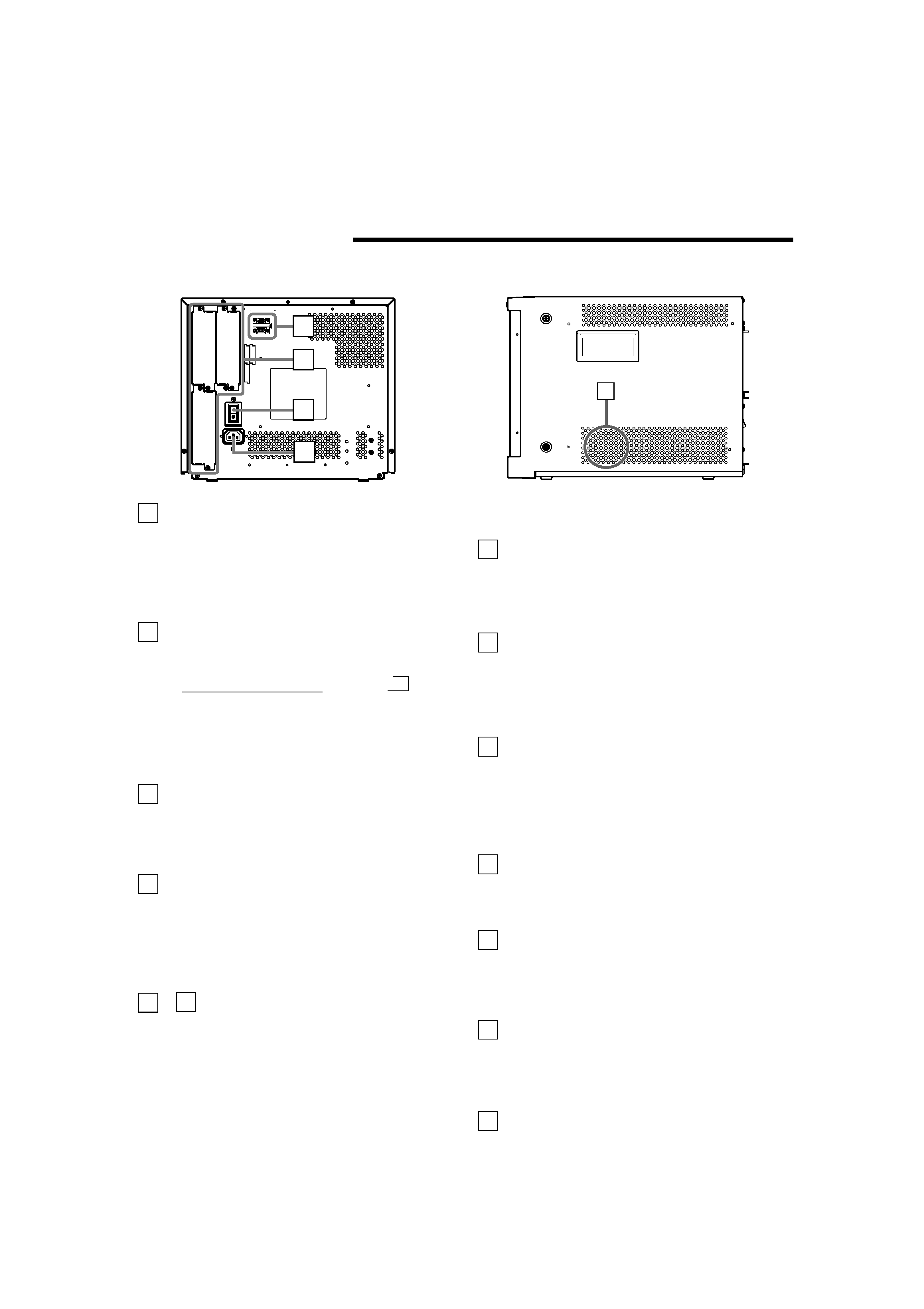
REAR/SIDE VIEW
<Rear Panel>
COLOR OFF button/lamp
Press the COLOR OFF button. The button lights and the
screen becomes monochrome. When the COLOR OFF
button is pressed while lit, the light goes off and the
normal screen is restored.
Use this function to confirm the noise in the brightness
signal or to confirm the white balance.
NOTE: This function is invalid with the RGB-input screen.
SCREENS CHECK button/lamp
Press the SCREENS CHECK button. The button lights
and the screen changes in the following order:
Normal screen[Red screen[Green screen
Blue screenp
Press the SCREENS CHECK button when the blue
screen is displayed. The light goes off and the normal
screen is restored.
Use this function to confirm or adjust CHROMA or
PHASE.
NOTE: This function is invalid with the RGB-input screen.
ASPECT button/lamp
When the ASPECT button is pressed while the screen
ratio is 4:3, the button lights and the screen ratio changes
to 16:9. When the ASPECT button is pressed while lit, the
light goes off and the normal screen is restored.
NOTE: This function is invalid with the RGB-input screen.
AREA MARKER button/lamp
When the AREA MARKER button is pressed while the
screen ratio is 16:9, the button lights and the white
marker is displayed. This shows the screen size (area)
set on the menu. When the AREA MARKER button is
pressed while lit, the light goes off and the normal screen
is restored.
NOTE: This function is invalid with the RGB-input screen.
INPUT SELECT buttons/lamps
Press the unlit button. The button lights and the input
signal is changed. (any other lit button goes off.)
When the lit button is pressed, the status of the current
input signal is displayed (for approx. 3 seconds). Buttons
A through F correspond to the signals input via the input
cards installed in SLOT 1 through SLOT 3.
A, B : select the picture from the SLOT 1 input card.
C, D : select the picture from the SLOT 2 input card.
E, F : select the picture from the SLOT 3 input card.
14
MAKE
SLO
T
1
RS-232C
SLO
T
2
SLO
T
3
MAIN POWER
26
27
28
29
30
<Side Panel>
Refer to pages 6 and 8 for correspondence between the
input terminals and the INPUT SELECT buttons.
Power lamp
Unlit
: The main power is OFF.
Orange : The main power is ON, but the monitor's power
is OFF (in stand-by mode).
Green : The main power is ON, and the monitor's power
is ON (in normal operation mode).
POWER switch
Press the power switch to turn the monitor's power ON or
OFF when the main power is ON.
NOTE: When RUSH DELAY TIME is set to SLOW in the
set-up menu, it takes approx. 3.2 seconds for the
power to actually turn ON after the power switch is
pressed.
REMOTE (external control) terminals
Terminals for controlling the monitor from an external unit.
MAKE/TRIGGER terminal (Upper):
Enables the monitor to be controlled by closing the circuit
(point of contact) connected to the terminal.
RS-232C terminal (Lower):
Enables the monitor to be controlled from a personal
computer via serial communication.
Input card slots (SLOT 1 -- SLOT 3)
Optional input cards can be installed in these slots. Input
cards are not provided when you purchase the monitor.
NOTE: It is not possible to input video or audio signals to
the monitor when no input cards are installed.
Main power switch
Press the switch to turn the main power ON or OFF.
When the main power is ON, the power lamp on the front
panel lights in yellow and the monitor enters the stand-by
mode.
I : ON
: OFF
AC inlet
Power input connector. Connect the provided AC power
cord to an AC outlet (120 V/230 V AC, 50 Hz/60 Hz).
* Attach the provided Power Cord Holder to the AC inlet to
prevent accidental disconnection of the AC power cord.
Refer to page 10 for details.
Built-in speaker (monaural)
Outputs the input audio.
15
16
17
18
23
24
25
26
27
28
29
30
[
LCT1117-001A
02.1.29, 2:31 PM
5