INSTRUCTIONS
DT-V100CG
LCT1811-001A
MULTI-FORMAT MONITOR
The supplied wide mask is attached to the monitor in the
illustration on the right.
LCT1811-001A_Cover.p65
05.3.9, 8:08 PM
1
2
SCREEN BURN
It is not recommended to keep a certain still image
displayed on screen for a long time as well as displaying
extremely bright images on screen. This may cause a
burning (sticking) phenomenon on the screen of cathode-ray
tube. This problem does not occur as far as displaying
normal video playback motion images.
PRECAUTIONS
Use only the power source specified on the unit.
(120 V/220-240 V AC, 50 Hz/60 Hz)
Keep flammable material, water, and metal objects away
from the unit especially the interior of the unit.
This unit incorporates high voltage circuitry.
For your own safety and that of your equipment, do not
attempt to modify or disassemble this monitor.
There are no user-serviceable parts inside.
HANDLING
Avoid shocks or vibrations. These may damage the unit and
cause it to malfunction.
Do not block the ventilation slots.
Do not expose this unit to high temperatures.
Extended exposure to direct sunlight or a heater could
deform the cabinet or cause the performance of internal
components to deteriorate.
Do not place the unit near appliances generating strong
electric or magnetic fields. There can generate picture noise
and instability.
Keep the monitor clean by wiping the cabinet and CRT
screen with a piece of soft cloth. Do not apply thinner or
benzine. These chemicals can damage the finish and erase
printed letters. When the unit is excessively dirty, use a
diluted neutral cleanser, then wipe away the cleanser with a
dry cloth.
WARNINGS
To prevent fire or shock hazard, do not expose this
monitor to rain or moisture. Dangerous high voltages
are present inside the unit. Do not remove the back
cover of the cabinet. When servicing the monitor,
consult qualified service personnel. Never try to service
it yourself.
WARNING : THIS APPARATUS MUST
BE EARTHED.
SAFETY PRECAUTIONS
Improper operations, in particular alternation of high
voltage or changing the type of tube may result in x-ray
emission of considerable dose. A unit altered in such a
way no longer meets the standards of certification, and
must therefore no longer be operated.
This monitor is equipped with a 3-blade grounding-type
plug to satisfy FCC rule. If you are unable to insert the
plug into the outlet, contact your electrician.
FCC NOTICE (U.S.A. only)
CAUTION: Changes or modifications not approved by
JVC could void the user's authority to operate the
equipment.
NOTE: This equipment has been tested and found to
comply with the limits for a Class A digital device,
pursuant to Part 15 of the FCC Rules. These limits are
designed to provide reasonable protection against harmful
interference when the equipment is operated in a
commercial environment. This equipment generates, uses,
and can radiate radio frequency energy and, if not installed
and used in accordance with the instruction manual, may
cause harmful interference to radio communications.
Operation of this equipment in a residential area is likely to
cause harmful interference in which case the user will be
required to correct the interference at his own expense.
Notice (U.S.A. only)
This product utilizes both a Cathode Ray Tube (CRT) and
other components that contain lead. Disposal of these
materials may be regulated in your community due to
environmental considerations. For disposal or recycling
information please contact your local authorities, or the
Electronics Industries Alliance: <http://www.eiae.org.>
Thank you for purchasing this JVC Multi-Format Monitor. Before using it, read and follow all
instructions carefully to take full advantage of the monitor's capabilities.
In order to prevent any fatal accidents caused by misoperation or mishandling the monitor, be fully aware of all the following
precautions.
WARNING
This is a class A product. In a domestic environment this
product may cause radio interference in which case the
user may be required to take adequate measures.
EN02-03_LCT1811-001A-H.p65
05.3.28, 9:48 AM
2
3
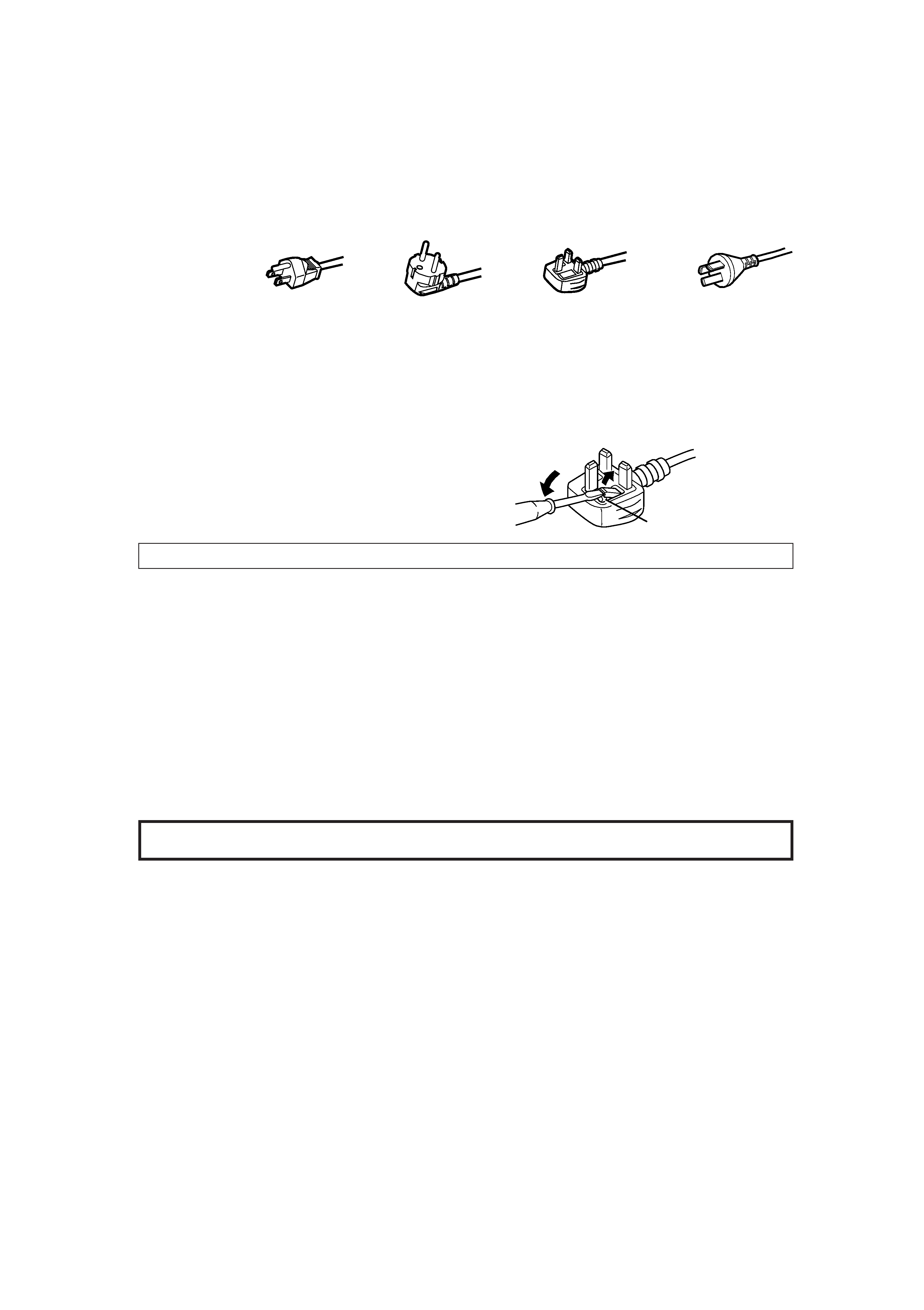
POWER CONNECTION
The power supply voltage rating of this product is AC 120 V (For U.S.A. and Canada only) and AC 220-240 V (For European
countries, United Kingdom, or China), the power cord attached conforms to the following power supply voltage and countries. Use
only the power cord designated to ensure Safety and EMC regulations of each countries.
Power cord
Power supply voltage : AC 120 V
AC 220-240 V
AC 220-240 V
AC 220-240 V
Countries
: U.S.A. and Canada
European countries
United Kingdom
China
Warning:
Do not use the same Power Cord for AC 120 V as for AC 220-240 V. Doing so may cause malfunction, electric shock or fire.
Note for the United Kingdom power cord only
The plug on the United Kingdom power cord has a built-in fuse. When replacing the fuse, be sure to use only a correctly rated
approved type, re-fit the fuse cover.
(Consult your dealer or qualified service personnel.)
How to replace the fuse
Open the fuse compartment with the blade screw driver, and
replace the fuse.
(* An example is shown in the illustration.)
Fuse
EMC Supplement (Europe only)
This equipment is in conformity with the provisions and protection requirements of the corresponding European Directives. This
equipment is designed for professional video appliances and can be used in the following environments:
Controlled EMC environment (for example purpose built broadcasting or recording studio), and the rural outdoors
environment (far away from railways, transmitters, overhead power lines, etc.)
In order to keep the best performance and furthermore for electromagnetic compatibility we recommend to use cables not
exceeding the following length:
Cable
Length
Power cord
(attached cable)
2.0 m
Video signal cable
(coaxial cable)
2.0 m
Audio signal cable
(shielded cable)
1.0 m
RS-485 cable
(twist pair cable)
10.0 m
The inrush current of this apparatus is 35 ampere.
Caution
When in case that the strong electromagnetic waves or magnetism is near the audio cable or the signal cable, the sound or the
picture will contain noise. In such case, please keep the cable away from the sources of the disturbance.
CONTENTS
SAFETY PRECAUTIONS ........................................................................ 2
Controls and Features ........................................................................... 4
Preparation ............................................................................................. 7
Basic Menu Operations
(MAIN MENU, SET-UP MENU) .............................................................. 9
How to Use MAIN MENU ...................................................................... 11
How to Use SET-UP MENU .................................................................. 14
How to Use the External Control ........................................................ 19
Troubleshooting ................................................................................... 21
Self-check Indications .......................................................................... 22
Specifications ....................................................................................... 23
EN02-03_LCT1811-001A-H.p65
05.5.18, 9:12 PM
3
4
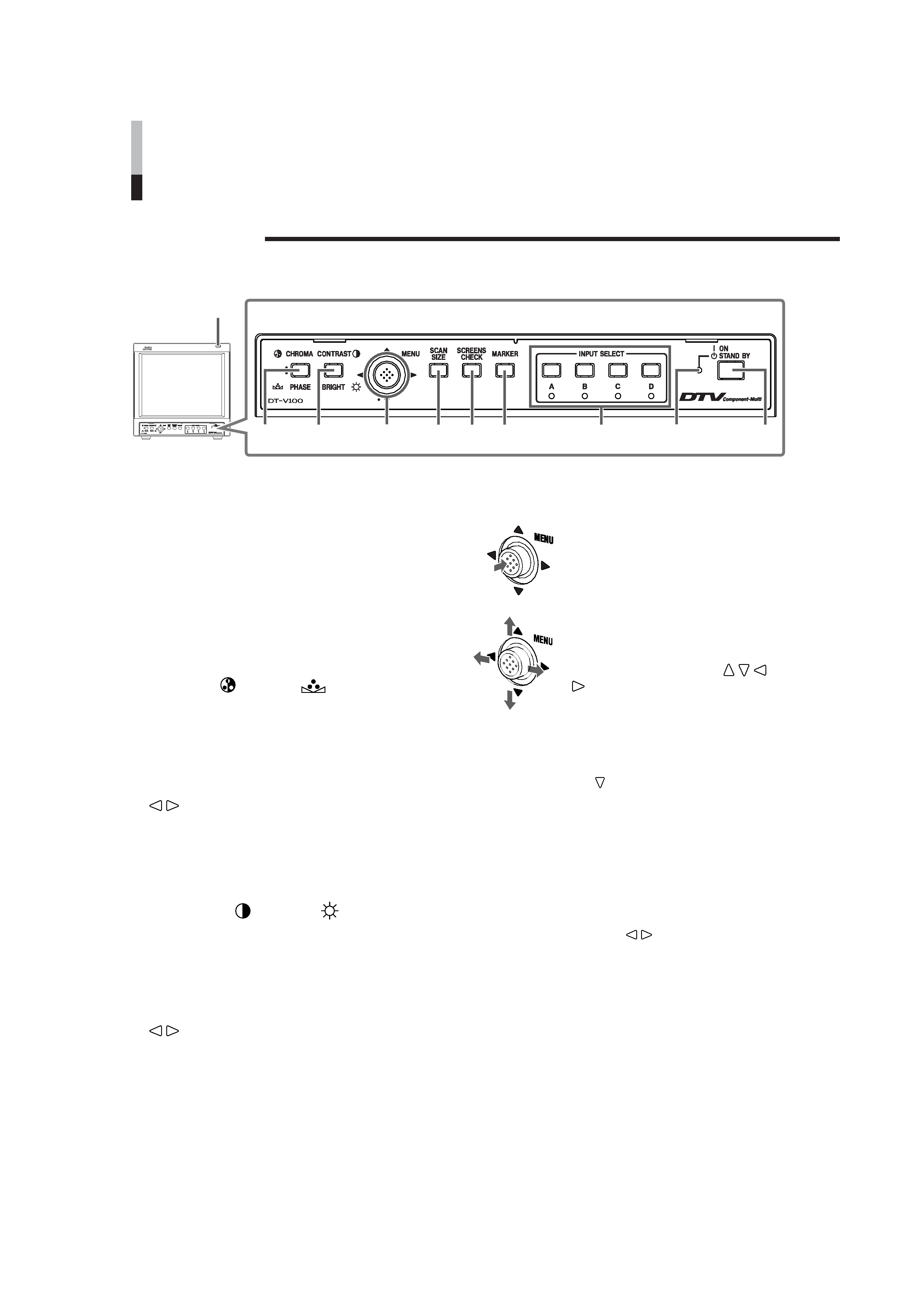
Controls and Features
Front Panel
1 Tally lamp
This lamp is controlled by the tally function of
the MAKE/TRIGGER terminal.
"How to Use the MAKE/TRIGGER Terminal" on page 19
· You can set the lamp color to red or green in "TALLY
SELECT."
"TALLY SELECT" on page 15
· When you set "FORMAT IND." to "ON," this lamp works as
the format indicator showing the format of the signal
currently input.
"FORMAT IND." on page 15
2 CHROMA ( )/PHASE (
) button
Activates the Chroma (picture color density)
adjustment mode or the Phase (picture hue)
adjustment mode. Each time you press the
button, the adjustment modes change.
CHROMA
"PHASE
To adjust the value, move the MENU control to
/
.
NOTES:
· CHROMA is not adjustable when the B/W (50 Hz/60 Hz)
signal is input.
· PHASE is not adjustable when the PAL signal or the B/W
(50 Hz/60 Hz) signal is input.
3 CONTRAST ( )/BRIGHT (
) button
Activates the picture contrast adjustment mode
or picture brightness adjustment mode. Each
time you press the button, the adjustment
modes change.
CONTRAST
"BRIGHTNESS
To adjust the value, move the MENU control to
/
.
4 MENU control
Displays or closes a menu screen.
While a menu screen is displayed,
selects or adjusts the menu items
by moving the control to
/ /
/
.
To display the SET-UP MENU:
Press the CHROMA/PHASE button while keeping to move
the MENU control to
.
To select the channel of the audio output from the
audio output terminal on the Multi-Format SDI Unit
(option):
NOTE:
This function is valid when using the Multi-Format SDI Unit
(option).
When HD/SD SDI signal including EMBEDDED AUDIO
signal is input, you can select the channel of the audio
signal output from the audio output terminal.
Move the MENU control to
/
to select the audio output
mode while no menu screen is displayed.
· If you change the audio output mode, the channel of the
audio signal output from the audio output terminal
changes. Refer also to the Multi-Format SDI Unit's
manual.
· Set the group of the audio output modes you want to
select beforehand.
"E. AUDIO GROUP" on page 15
1
23
4
5
6
7
8
9
p
EN04-06_LCT1811-001A-H.p65
05.4.26, 6:38 PM
4
5
5 SCAN SIZE button
Reduces the screen size (under-scan) so that
the whole screen is displayed.
6 SCREENS CHECK button
Each time you press this button, the screen
changes in the following order:
Normal screen[Monochrome screen[
Red screen[Green screen[Blue screen[
(back to the beginning)
7 MARKER button
Turns the MARKER function ON/OFF.
· MARKER function includes MARKER SELECT, ZOOM,
ASPECT SELECT, and SAFETY MARKER functions.
"MARKER" on page 12
NOTES:
· Functions do not operate when they are set to OFF in the
"MARKER" menu.
· Initial setting of each function in the "MARKER" menu is OFF.
Before you use the MARKER function, you must change the
"MARKER" menu settings first.
· The ZOOM function does not operate in the under-scan mode.
· When the ZOOM function is operated, the MARKER SELECT
and the SAFETY MARKER function in the "MARKER" menu do
not work.
8 INPUT SELECT buttons/lamps
Select an input to display.
A:
Select the video signal input to the VIDEO A
terminal.
B:
Select the video signal input to the VIDEO B
terminal.
C/D: Select the signal input to the input unit (option) which
is attached to the rear panel.
· For details about how to select the input signal through
the input unit, refer to the input unit's manual.
· The corresponding lamp of the input currently selected
lights up.
9 Power lamp
Unlit:
The main power is off.
Orange: The main power is on and the monitor is in
stand-by mode.
Green:
The monitor is on.
p Stand-by button
Turns on and off the monitor when the main
power is on.
NOTES:
· You cannot turn on the monitor if the main power switch on the
rear panel is not turned on.
· You can set the delay time between when the stand-by button is
pressed and when the monitor actually turns on.
"RUSH DELAY TIME" on page 15
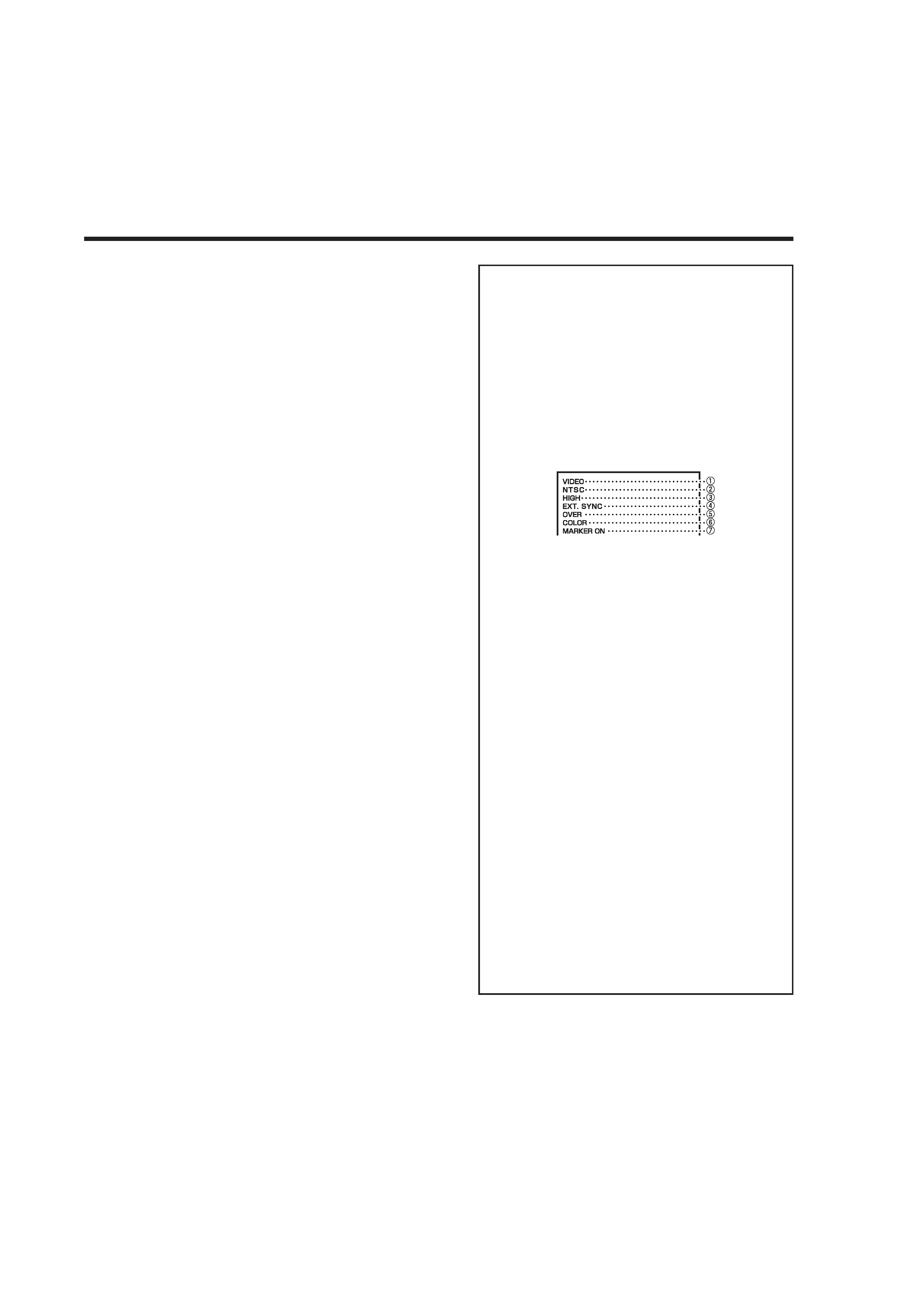
About the status display
Displays information of the current input selection and the
monitor settings for about 3 seconds.
To show the status display, set "STATUS DISPLAY" to
"AUTO" or "MANUAL" beforehand.
"STATUS DISPLAY" on page 18
Pressing the INPUT SELECT button currently selected
shows the status display.
NOTE:
When "STATUS DISPLAY" is set to "AUTO," the status display also
appears on the screen if you change the inputs or the signal
condition changes.
1 Input status
2 Signal format
· "NO SYNC" is displayed when no video signal is input
or no synchronized signal is detected.
· If "NO SYNC" is displayed even though a video signal is
input, check the setting of "SYNC SELECT."
"SYNC SELECT" on page 15
· "Out of range" is displayed when a noncompliant signal
is input.
3 Setting of "COLOR TEMP."
"COLOR TEMP." on page 16
" * " is displayed if white balance is adjusted in the
"COLOR TEMP./BAL." menu.
4 Appears when "SYNC SELECT" is set to "EXT."
(External synchronization)
"SYNC SELECT" on page 15
5 Setting of SCAN SIZE
"5 SCAN SIZE button" on the left column
OVER:
Over-scan
UNDER: Under-scan
6 Setting of SCREENS CHECK
"6 SCREENS CHECK button" on the left column
COLOR: Normal screen
MONO: Monochrome screen
R ONLY: Red screen
G ONLY: Green screen
B ONLY: Blue screen
7 Setting of MARKER
"7 MARKER button" on the left column
EN04-06_LCT1811-001A-H.p65
05.4.26, 6:39 PM
5