For Customer Use :
Enter below the Serial No. which is located on the body.
Retain this information for future reference.
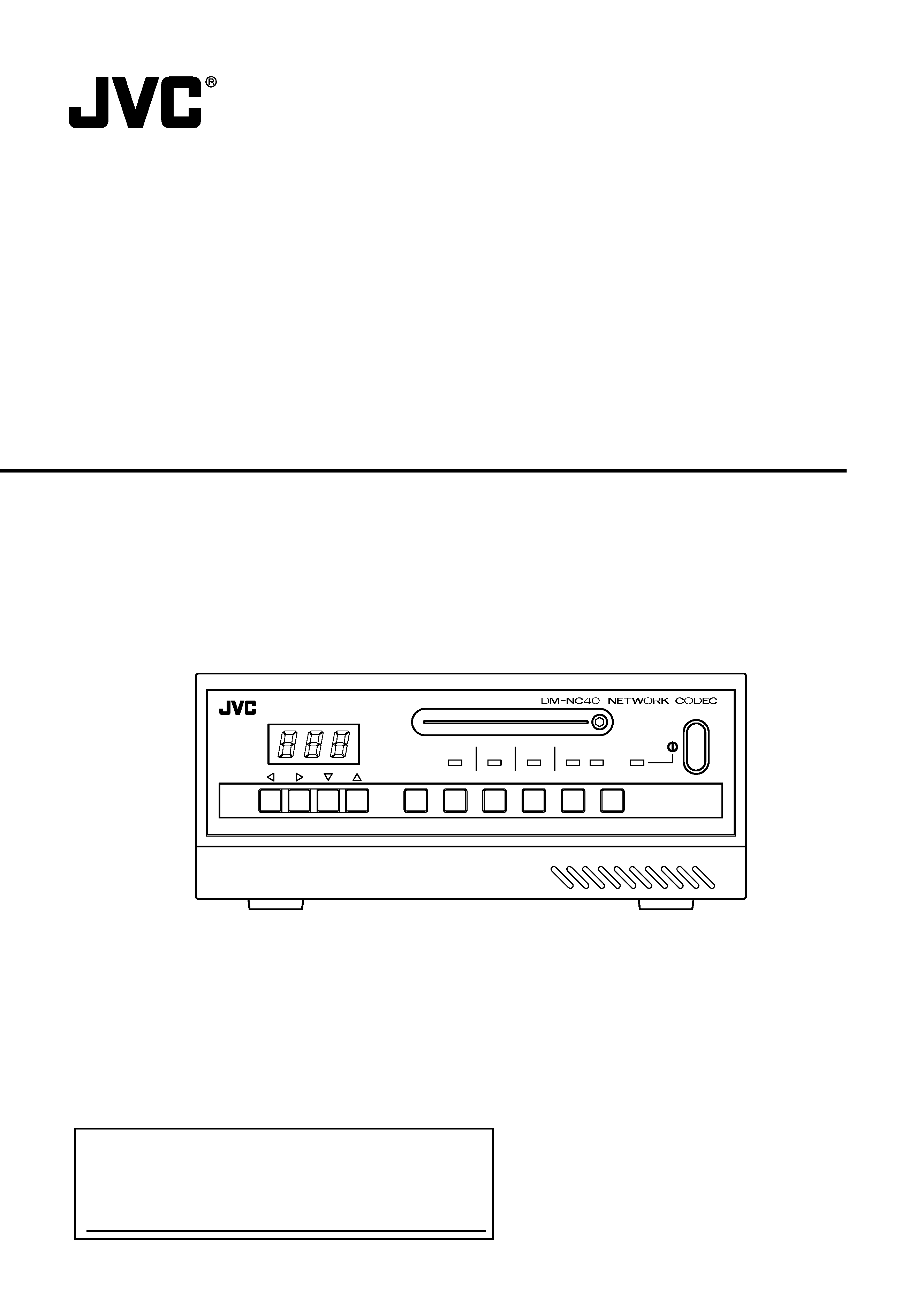
Model No. DM-NC40
Serial No.
DMNC40
INSTRUCTIONS
NETWORK CODEC
LST0176-001A
POWER
IN 2
IN 1
HOLD
DECODE
ENCODE
CF
PLAY
STOP
HOLD
SELECT
P P
in
This instruction book is mode from 100%
recycled paper.

2
1. Read all of these instructions.
2. Save these instructions for later use.
3. All warnings on the product and in the operating instructions should be adhered to.
4. Unplug this appliance system from the wall outlet before cleaning. Do not use liquid cleaners or aerosol cleaners.
Use a damp cloth for cleaning.
5. Do not use attachments not recommended by the appliance manufacturer as they may cause hazards.
6. Do not use this appliance near water for example, near a bathtub, washbowl, kitchen sink, or laundry tub, in a wet
basement, or near a swimming pool, etc.
7. Do not place this appliance on an unstable cart, stand, or table. The appliance may fall, causing
serious injury to a child or adult, and serious damage to the appliance.
Use only with a cart or stand recommended by the manufacturer, or sold with the appliance.
Wall or shelf mounting should follow the manufacturer's instructions, and should use a mounting
kit approved by the manufacturer.
An appliance and cart combination should be moved with care. Quick stops, excessive force,
and uneven surfaces may cause the appliance and cart combination to overturn.
8. Slots and openings in the cabinet and the back or bottom are provided for ventilation, and to
insure reliable operation of the appliance and to protect it from overheating, these openings
must not be blocked or covered. The openings should never be blocked by placing the appliance on a bed, sofa, rug,
or other similar surface. This appliance should never be placed near or over a radiator or heat register. This appliance
should not be placed in a built-in installation such as a bookcase unless proper ventilation is provided.
9. This appliance should be operated only from the type of power source indicated on the marking label. If you are not
sure of the type of power supplied to your home, consult your dealer or local power company. For appliance designed
to operate from battery power, refer to the operating instructions.
10. This appliance system is equipped with a 3-wire grounding type plug (a plug having a third (grounding) pin). This
plug will only fit into a grounding-type power outlet. This is a safety feature. If you are unable to insert the plug into the
outlet, contact your electrician to replace your obsolete outlet. Do not defeat the safety purpose of the grounding
plug.
11. For added protection for this product during a lightning storm, or when it is left unattended and unused for long
periods of time, unplug it from the wall outlet and disconnect the antenna or cable system. This will prevent damage
to the product due to lightning and power-line surges.
12. Do not allow anything to rest on the power cord. Do not locate this appliance where the cord will be abused by
persons walking on it.
13. Follow all warnings and instructions marked on the appliance.
14. Do not overload wall outlets and extension cords as this can result in fire or electric shock.
15. Never push objects of any kind into this appliance through cabinet slots as they may touch dangerous voltage points
or short out parts that could result in a fire or electric shock. Never spill liquid of any kind on the appliance.
16. Do not attempt to service this appliance yourself as opening or removing covers may expose you to dangerous
voltage or other hazards. Refer all servicing to qualified service personnel.
17. Unplug this appliance from the wall outlet and refer servicing to qualified service personnel under the following
conditions:
a. When the power cord or plug is damaged or frayed.
b. If liquid has been spilled into the appliance.
c. If the appliance has been exposed to rain or water.
d. If the appliance does not operate normally by following the operating instructions. Adjust only those controls that
are covered by the operating instructions as improper adjustment of other controls may result in damage and will
often require extensive work by a qualified technician to restore the appliance to normal operation.
e. If the appliance has been dropped or the cabinet has been damaged.
f.
When the appliance exhibits a distinct change in performance this indicates a need for service.
18. When replacement parts are required, be sure the service technician has used replacement parts specified by the
manufacturer that have the same characteristics as the original part. Unauthorized substitutions may result in fire,
electric shock, or other hazards.
19. Upon completion of any service or repairs to this appliance, ask the service technician to perform routine safety
checks to determine that the appliance is in safe operating condition.
IMPORTANT SAFEGUARDS
3
SAFETY PRECAUTIONS
FOR USA AND CANADA
RISK OF ELECTRIC SHOCK
DO NOT OPEN
AUTION :
TO REDUCE THE RISK OF ELECTRIC SHOCK,
DO NOT REMOVE COVER (OR BACK).
NO USER SERVICEABLE PARTS INSIDE.
REFER SERVICING TO QUALIFIED SERVICE PERSONNEL.
The exclamation point within an equilateral triangle is
intended to alert the user to the presence of important
operating and maintenance (servicing) instructions in
the literature accompanying the appliance.
The lightning flash with arrowhead symbol, within an
equilateral triangle is intended to alert the user to the
presence of uninsulated "dangerous voltage" within the
product's enclosure that may be of sufficient magni-
tude to constitute a risk of electric shock to persons.
INFORMATION
This equipment has been tested and found to comply with the limits
for a Class B digital device, pursuant to Part 15 of the FCC Rules.
These limits are designed to provide reasonable protection against
harmful interference in a residential installation. This equipment
generates, uses, and can radiate radio frequency energy and, if not
installed and used in accordance with the instructions, may cause
harmfull interfrence to radio communications. However, there is no
guarantee that interference will not occur in a particular installation.
If this equipment does cause harmful interference to radio or
television reception, which can be determined by turning the
equipment off and on, the user is encouraged to try to correct the
interference by one or more of the following measures:
Reorient or relocate the receiving antenna.
Increase the separation between the equipment and receiver.
Connect the equipment into an outlet on a circuit different from
that to which the receiver is connected.
Consult the dealer or an experienced radio/TV technician for help.
CAUTION
CHANGES OR MODIFICATIONS NOT APPROVED BY JVC
COULD VOID USER'S AUTHORITY TO OPERATE THE
EQUIPMENT.
INFORMATION FOR USA
THIS DEVICE COMPLIES WITH PART 15 OF THE FCC RULES.
OPERATION IS SUBJECT TO THE FOLLOWING TWO
CONDITIONS : (1) THIS DEVICE MAY NOT CAUSE HARMFUL
INTERFERENCE, AND (2) THIS DEVICE MUST ACCEPT ANY
INTERFERENCE RECEIVED, INCLUDING INTERFERENCE
THAT MAY CAUSE UNDESIRED OPERATION
INFORMATION (FOR CANADA)
RENSEIGNEMENT (POUR CANADA)
This Class B digital apparatus complies with Canadian
ICES-003.
Cet appareil numérique de la Class B est conforme à la norme
NMB-003 du Canada.
CAUTION
NOTE:
The rating plate (serial number plate) is on the rear panel.
WARNING:
TO REDUCE THE RISK OF FIRE OR ELECTRIC
SHOCK, DO NOT EXPOSE THIS APPLIANCE TO
RAIN OR MOISTURE.
This unit should be used with 120V AC only.
CAUTION:
To prevent electric shocks and fire hazards, do NOT use
any other power source.
CAUTION
To prevent electric shock, do not open the cabinet. No user servicea-
ble parts inside. Refer servicing to qualified service personnel.
AVERTISSEMENT :
POUR EVITER LES RISQUES D'INCENDIE OU
D'ELECTROCUTION, NE PAS EXPOSER
L'APPAREIL A L'HUMIDITE OU A LA PLUIE.
Ce magnétoscope ne doit être utilisé que sur du courant
direct en 120V.
ATTENTION :
Afin d'eviter tout resque d'incendie ou d'électrocution,
ne pas utillser d'autres sources d'alimentation électrique.
REMARQUE :
La plaque d'identification (numéro de série) se trouve sur le panneau
arrière de l'appareil.

4
Video/Audio codec
The unit is equipped with both encoding and
decoding features.
The unit is also equipped with an echo cancel-
ler feature.
High-picture quality MPEG-4 codec
· Encoding up to 2Mbps
· 30fps video display at 352
240 resolution
PinP (Picture-in-Picture) feature
Two camera video images can be combined
for display on the PC or monitor.
Built-in CF (Compact Flash) slot
Synchronizes with the alarm for recording of
video images to a CF card (not included).
(JPEG images only)
ISMA streaming
ISMA-compliant video and audio streaming.
Contact the nearest JVC-authorized service
agent for details concerning ISMA-compliant
players.
External control terminal
Control devices such as monitoring camera
system, etc.
Unicast and multicast transmission
Supports unicast and multicast for various sys-
tem solutions.
(Up to 5 streams for unicast)
Features
How to view this manual
s Symbols used
Items concerning the operations of this product are described.
References concerning the usage, restrictions, etc. of this product are described.
Reference pages and reference items are indicated.
s Button names in operation procedures are enclosed using [ ].
Example: Menu button ¡ [Menu]
s About the contents of this manual
q All rights reserved by JVC. Unauthorized duplication or reprinting of this manual, in whole or in part, is
strictly prohibited.
q Windows is a registered trademark of Microsoft Corporation in the U.S.
q All other product names used in this manual are trademarks or registered trademarks of their respective
companies. Please note that marks such as TM, ®, ©, etc. have been omitted in this manual.
q Illustrated designs, specifications and other contents of this manual are subject to change without prior
notice.
Note
Memo
Thank you for purchasing this JVC product. Before operating this unit, please read this instructions carefully
to ensure the best possible performance.
These instructions are for DM-NC40U.

5
Intr
oduction
Step 5 Mode Setup
5-1
Setting in the MODE SETUP Screen ...........
29
Step 6 Detailed Setup
6-1
NETWORK SETUP screen ................... 30
6-2
ENCODE PARAMETERS screen ......... 32
6-3
TELEPHONE BOOK screen .................. 34
6-4
SECURITY SETUP screen .................... 35
6-5
ALARM SETUP screen .......................... 37
6-6
OUTPUT PIN SETUP screen ............... 39
6-7
SERIAL PORT SETUP screen ............... 40
6-8
CF CARD SETUP screen ..................... 41
Operating the Teleconference System ............. 42
Operating the Monitor System ......................... 44
Operating the ISMA Server System ................. 47
DHCP Operations and
IP Address Display during Startup ......... 48
DHCP Operation ........................................... 48
IP Address Display ........................................ 48
Operating the CF Card ..................................... 49
Operating in the CF CARD SETUP screen ... 49
Operating with CF Card Reader ................... 50
Operating of FTP .......................................... 51
Settings Using the Terminal Software of a PC ... 53
Settings by Telnet of the PC ............................. 55
About the Alarm ............................................... 56
Specifications ................................................... 58
Features ................................................................ 4
Contents ................................................................ 5
Operational Environment ...................................... 6
Cautionary Notes .................................................. 7
Names and Operations of Parts ............................ 8
Various Applications ............................................ 11
Preparation Flow ................................................. 12
Step 1 Connection/Installation
1-1
Connection Examples ............................ 13
1-2
Connecting a LAN Cable ....................... 17
1-3
Inserting a CF (Compact Flash) Card .... 17
1-4
SERIAL Ports and ALARM Port ............. 18
1-5
Connecting the Power Cord ................... 19
1-6
Attaching Rack Mount Brackets ............. 19
Step 2 PC Network Setup
2-1
Setting the IP Address of the PC ........... 20
(For Windows XP)
2-2
Setting the IP Address of the PC ........... 22
(For Windows 2000)
Step 3 Launching the Web Browser
3-1
About the Web Browser ......................... 24
3-2
About Access Restriction Levels ............ 25
3-3
Launching the Browser .......................... 26
Step 4 Initial Settings
4-1
Changing the IP Address of the Unit ...... 27
4-2
Time Setup ............................................. 28
Introduction
Contents
Operations
Others
Preparations