1
INFORMATION (For U.S.A.)
This equipment has been tested and found to comply with the limits for a Class B digital
device, pursuant to Part 15 of the FCC Rules. These limits are designed to provide
reasonable protection against harmful interference in a residential installation. This equipment
generates, uses, and can radiate radio frequency energy and, if not installed and used in
accordance with the instructions, may cause harmful interference to radio communications.
However, there is no guarantee that interference will not occur in a particular installation. If
this equipment does cause harmful interference to radio or television reception, which can be
determined by turning the equipment off and on, the user is encouraged to try to correct the
interference by one or more of the following measures:
Reorient or relocate the receiving antenna.
Increase the separation between the equipment and receiver.
Connect the equipment into an outlet on a circuit different from that to which the receiver is
connected.
Consult the dealer or an experienced radio/TV technician for help.
Caution
Changes or modifications not approved by JVC could void the user's authority to operate the
equipment.
Bottom
0106MNMMDWJSC
EN
© 2006 Victor Company of Japan, Limited
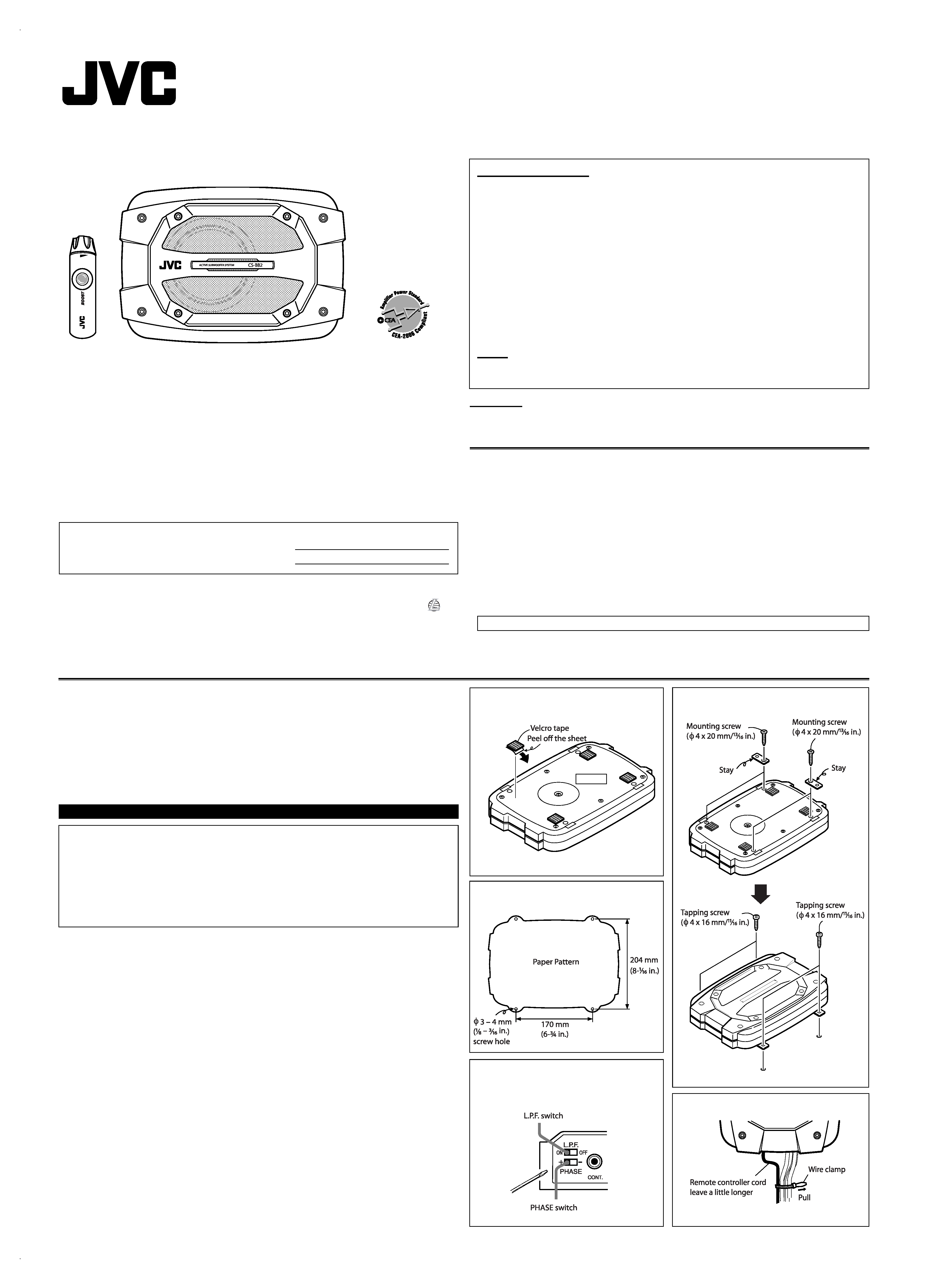
Mount this unit on a firm surface, such as on the floor.
· Since heat is generated in this unit, do not mount near flammable objects. In addition, mount in
an area that will not prevent the unit from dissipating heat.
· Do not mount the unit in the places subject to heat such as near a radiator, in a glove
compartment or under a car mat that will prevent the unit from dissipating heat.
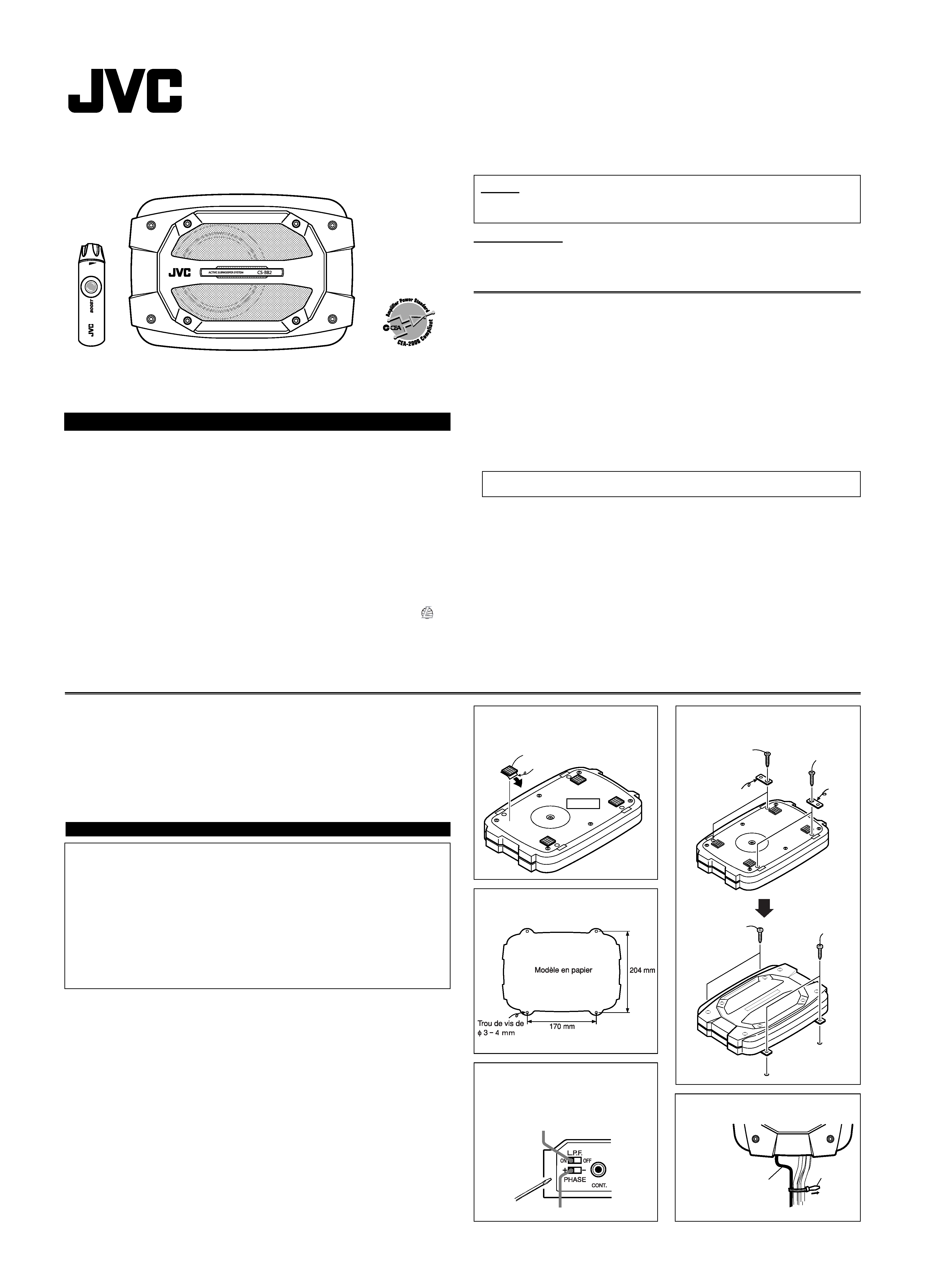
1 Attach the velcro tapes on the bottom
as illustrated.
2 Drill the screw holes using the
supplied paper pattern.
4 Install this unit with the supplied
screws.
How to use the supplied wire clamp
Cautions
· Never try to install this unit only with the velcro tape (supplied for skid-proof attachment).
· Fix it with the tapping screws (supplied) firmly.
· When mounting this unit, be sure to use the screws provided. If any other screws are used,
there is a risk of loosening the unit or damaging internal parts.
Before drilling holes on the floor to install the unit, make sure that there is a sufficient
space under the floor so that you do not drill holes in the fuel tank, etc.
· This unit generates a strong magnetic field. Never place cassette tapes or magnetic cards
nearby the unit; otherwise, data recorded in those media will be erased.
INSTALLATION
3 After connections, adjust the phase
and volume of this unit.
· For details, see "CONNECTIONS."
CS-BB2
ACTIVE SUBWOOFER SYSTEM: INSTRUCTIONS
LVT1544-001A
[J/U]
Thank you for purchasing a JVC product. Please read all instructions carefully before operation, to ensure
your complete understanding and to obtain the best possible performance from the unit.
For Customer Use:
Enter the Model No. and Serial No. which
are located on the top or bottom of the cabinet.
Retain this information for future reference.
Model No.
Serial No.
For safety....
· Do not raise the volume level too much, as this will block outside sounds, making driving dangerous.
CAUTIONS AND NOTES
This unit is designed to operate on 12 V DC, NEGATIVE ground electrical systems.
· To prevent short circuits, we recommend that you disconnect the battery's negative terminal
and make all electrical connections before installing the unit.
· Cover the unused terminals with insulating tape to prevent them from short circuiting.
· When an extension lead is used, it should be as thick and short as possible; connect it firmly
with insulating tape.
· Be sure to leave an appropriate space between the antenna and the wires of this unit.
· When replacing the fuse, only use a 10 A fuse.
· Do not let foreign objects get inside the unit.
· To keep the heat dissipation mechanism running effectively, wipe the accumulated dust off periodically.
· Using this subwoofer system with the volume on loud for a long period of time will exhaust the
battery, while the engine is turned off or while the engine is idling.
· This unit becomes very hot. Be careful not to touch the unit not only when using but for a while
after using.
DO NOT disassemble the units since there are no user serviceable parts inside.
CS-BB2[J/U].indd 1
CS-BB2[J/U].indd 1
1/23/06 4:56:33 PM
1/23/06 4:56:33 PM
2
When using LINE IN jacks
NOTES:
· The volume of this unit is set to the maximum when remote controller is not connected.
· If your receiver is equipped with the DSP (Digital Signal Processor), connect this unit to the Front Line Output jacks of the receiver.
· When connecting to the Line Output jacks, make sure that the output level of the receiver is 2 V or lower; otherwise, sounds will be distorted.
· Ground wire connection
· Do not connect the power lead to any other sources than the battery.
CONNECTIONS
Cautions
Ground wire
Firmly attach the ground wire to the metallic body or
to the chassis of the car--to the place uncoated with
paint (if coated with paint, remove the paint before
attaching the wire). Failure to do so may cause
damage to the unit.
· Do not cut off the fuse; otherwise, it may be short-circuited, and cause a fire.
· Do not connect the blue with white stripes to any other wire than the remote out (DC
12 V) and ACC power.
After connection, reconnect the battery negative terminal and make sure stop lamps
and others can operate normally.
The fuse is cut off.
Fuse
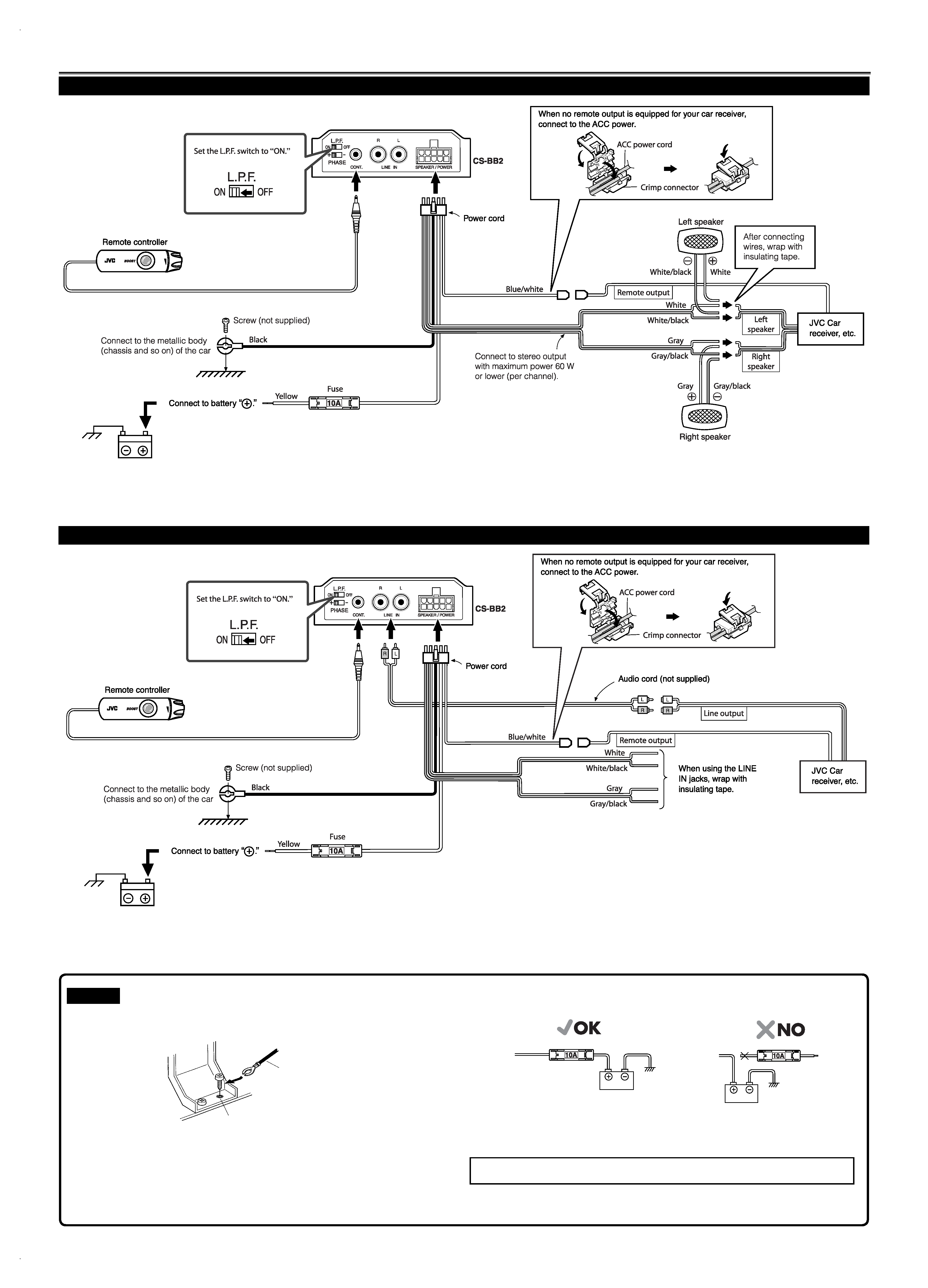
When using speaker input terminal
NOTES:
· The volume of this unit is set to the maximum when the remote controller is not connected.
· If your receiver is equipped with the DSP (Digital Signal Processor), connect this unit to the front speaker output of the receiver.
CS-BB2[J/U].indd 2
CS-BB2[J/U].indd 2
1/23/06 4:56:38 PM
1/23/06 4:56:38 PM
3
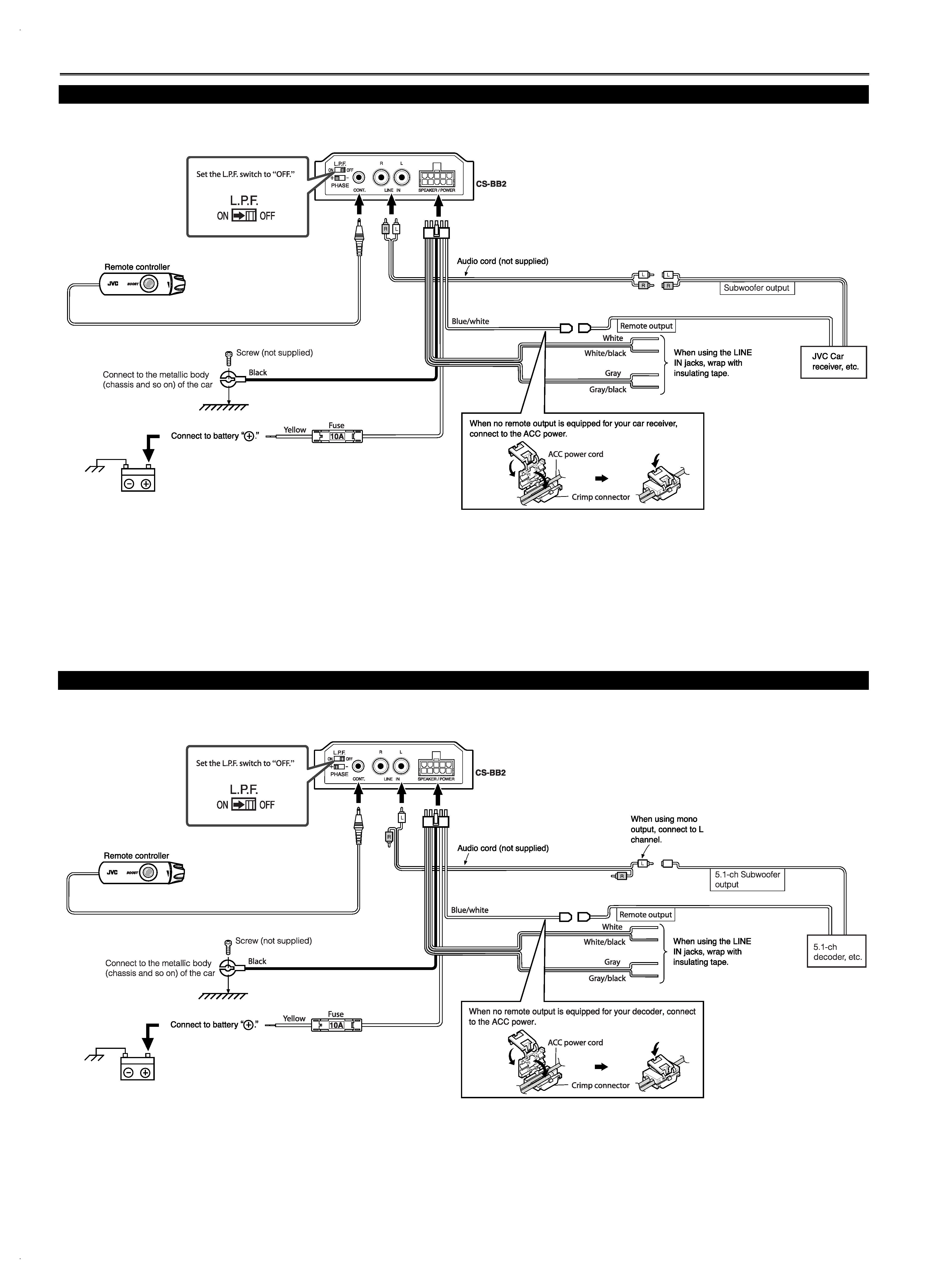
Set the subwoofer output level to the maximum on your car receiver.
· Use the supplied remote controller to adjust the volume. (When sound is distorted, lower the subwoofer output level on your car receiver.)
NOTES:
· When connecting to the Subwoofer Output jacks, make sure that the output level of the receiver is 2 V or lower; otherwise, sounds will be distorted.
· The volume of this unit is set to the maximum when remote controller is not connected.
Adjust the subwoofer output level on your car receiver.
CONNECTIONS
Set the subwoofer output level to the maximum on your decoder.
· Use the supplied remote controller to adjust the volume.
NOTES:
· When connecting to the 5.1-ch Subwoofer output jacks, make sure that the output level of the decoder is 2 V or lower; otherwise, sounds will be distorted.
· The volume of this unit is set to the maximum when remote controller is not connected.
Adjust the subwoofer output level on your car decoder.
When connecting to 5.1 channel subwoofer output
When connecting to subwoofer output
CS-BB2[J/U].indd 3
CS-BB2[J/U].indd 3
1/23/06 4:56:40 PM
1/23/06 4:56:40 PM
4
Use a CD with rich bass sound to test and adjust phase and sound.
Main Unit
TROUBLESHOOTING
For more details, consult JVC IN-CAR ENTERTAINMENT car audio dealer.
No sound is heard.
· Is the blue with white stripes connected correctly?
· Is audio cord connected to the LINE IN jacks?
· Is this subwoofer system grounded?
Alternator noise is heard.
· Keep the power cord away from the audio cord.
· Keep the audio cord away from other electrical cables in the car.
· Confirm if the ground wire is connected securely to a metal part of the car.
· Confirm if the noise originates in the receiver.
Remote Controller
SPECIFICATIONS
Type
Closed Active Subwoofer (Built-in amplifier)
Speaker Unit
14 cm (5-9/16 in.) cone
Input Terminal
LINE IN (1 system), 0.19 V/25 k
SPEAKER (1 system), 3.7 V
Power Output
32 W RMS x 2 channels at 2
and 1% THD + N
Signal-to-Noise Ratio
75 dBA (reference: 1 W into 2 )
Maximum Amplifier Power Output
60 W + 60 W (Impedance 2 + 2 )
Cut-off Frequency
110 Hz (L.P.F. switch "ON", 12 dB/oct low pass filter)
Crossover Frequency
20 Hz to 200 Hz (L.P.F. switch "ON")
20 Hz to 500 Hz (L.P.F. switch "OFF")
Sound Pressure Level
88 dB/ m (with line input: 0.03 V)
Level Control
50 dB to 0 dB (Center) to + 10 dB
Power Requirement
DC 14.4 V (11 V to 16 V allowance)
Negative ground
Dimensions (W/H/D)
290 mm × 60.5 mm × 200 mm
(11-7/16 in. x 2-7/16 in. x 7-7/8 in.)
Mass
2.1 kg (4.7lbs) (Excluding accessories)
Supplied Accessories
Remote controller (cord: 3 m/9.8 ft.) × 1
Power cord (3 m/9.8 ft.) × 1
Stay (Metal tool ) × 4
Tapping screw ( 4 × 16 mm/11/16 in.) × 4
Mounting screw ( 4 × 20 mm/13/16 in.) × 4
Velcro tape × 4
Double-sided tape × 1
Crimp connector × 1
Wire clamp × 1
Design and specifications are subject to change without notice.
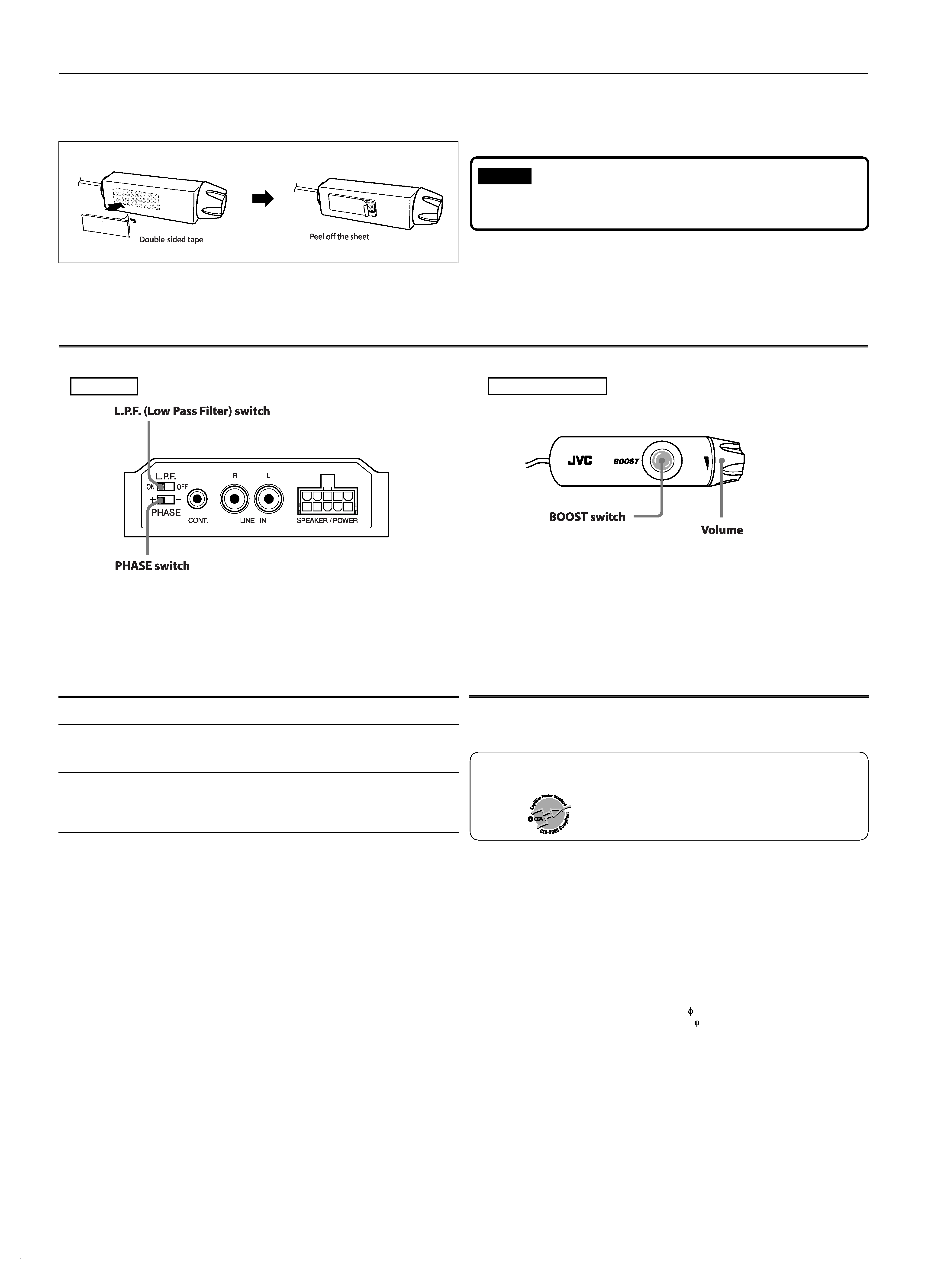
OPERATIONS
Attaching the remote controller
· Do not place the remote controller where it will be exposed to direct sunlight.
PHASE AND SOUND ADJUSTMENT
When your car receiver is equipped with
Low Pass Filter, switch to "OFF."
Switch to the position (+/) which
gives you better sound.
Turns on and off the subwoofer
output. When it is on, the lamp
lights up.
Adjust the subwoofer output level.
(Center: 0 dB)
Cautions
· When using this unit, deactivate all sound adjustment functions except volume level;
otherwise, sound may be distorted.
CS-BB2[J/U].indd 4
CS-BB2[J/U].indd 4
1/23/06 4:56:40 PM
1/23/06 4:56:40 PM
1
0106MNMMDWJSC
FR
© 2006 Victor Company of Japan, Limited
1 Fixez les bandes velcro sous
l'appareil comme montré sur
l'illustration.
2 Percez les tours en utilisant le
modèle en papier fourni.
Commutateur L.P.F.
Commutateur PHASE
4 Installez cet appareil avec les vis
fournis.
Plaque
Plaque
Vis de montage
(
4 x 20 mm)
Vis autotaraudeuse
(
4 x 16 mm)
Vis autotaraudeuse
(
4 x 16 mm)
Vis de montage
(
4 x 20 mm)
Cordon de la télécommande
laissez un peu de mou
Serre-fil
Tirez
Comment utiliser le serre-fil fourni
Attention
INSTALLATION
3 Après la connexion, ajustez la
phase et le volume de cet appareil.
· Pour plus de détails, référez-vous à
"CONNEXIONS".
CS-BB2
SYTÈME DE CAISSON DE GRAVE ACTIF:
INSTRUCTIONS
Pour votre sécurité....
· N'augmentez pas trop le niveau du volume car cela peut bloquer les sons de l'extérieur et
rendre la conduite dangereuse.
ATTENTION ET REMARQUES
Cet appareil est conçu pour fonctionner avec système électrique de 12 V CC avec mise à la
masse NÉGATIVE.
· Pour éviter les courts-circuits, nous vous recommandons de déconnecter la borne négative
de la batterie et de réaliser toutes les connexions électriques avec d'installer l'appareil.
· Recouvrir les bornes inutilisées avec du ruban isolant pour éviter de les court-circuiter.
· Si vous utilisez un fil de prolongement, celui-ci doit être aussi épais et aussi court que
possible. Connectez-le solidement avec un ruban adhésif.
· Bien laisser un espace suffisant entre I'antenne et les fils de cet appareil.
· Lors du remplacement du fusible, utilisez uniquement un fusible de 10 A.
· Ne laissez pas des objets étrangers pénétrer à l'intérieur de l'appareil.
· Ne pas laisser pénétrer de cailloux, de sable ou d'objets métalliques dans I'appareil.
· Utiliser ce système de caisson de grave à un volume élevé pendant une longue période de
temps déchargera la batterie, si le moteur est arrêté ou tourne au ralenti.
· Cet appareil devient très chaud. Faites attention de ne pas le toucher pendant son utilisation
mais aussi après sont utilisation.
NE DEMONTEZ PAS l'appareil. Il n'y a aucune pièce réparable par l'utilisateur à
l'ntérieur.
Merci pour avoir acheté un produit JVC. Veuillez lire attentivement toutes les instructions avant
d'utiliser l'appareil afin de bien comprendre son fonctionnement et d'obtenir les meilleures
performances possibles.
Bande velcro
Décollez cette feuille
Dessous
FRANÇAIS
Montez cet appareil sur une surface ferme, comme le plancher.
· Comme cet appareil génère de la chaleur, ne le montez pas près d'objets inflammables.
De plus, choisissez un endroit où rien ne gênera la bonne dissipation de la chaleur de
l'appareil.
· Ne montez pas l'appareil dans un endroit sujet à la chaleur, tel que près d'un radiateur, dans
la boîte à gant ou sous un tapis de sol, où il ne pourra pas dissiper sa chaleur.
· N'essayez jamais d'installer cet appareil uniquement avec la bande velcro fournie pour
une fixation antidérapante.
· Fixez-le solidement avec les vis autotaraudeuse (fournies).
· Lors du montage de cet appareil, assurez-vous d'utiliser les vis fournies. Si vous utilisez
d'autres vis, il y a des risques que l'appareil se desserre ou que des pièces internes
soit endommagées.
Avant de percer des trous sur le plancher pour installer l'appareil, assurez-vous qu'il
y a suffisamment d'espace sous le plancher et que vous ne percez pas le réservoir
d'essence, etc.
· Cet appareil émet un champ magnétique puissant. Ne placez jamais des cassettes ou
des cartes magnétiques à proximité; sinon, les données enregistrées sur ces supports
seront effacées.
Attention
Tout changement ou toutes modifications non approuvés par JVC peut annuler l'autorité
de l'utilisateur d'utiliser l'appareil.
FR_CS-BB2[J]2.indd 1
FR_CS-BB2[J]2.indd 1
2006.1.23 4:56:40 PM
2006.1.23 4:56:40 PM