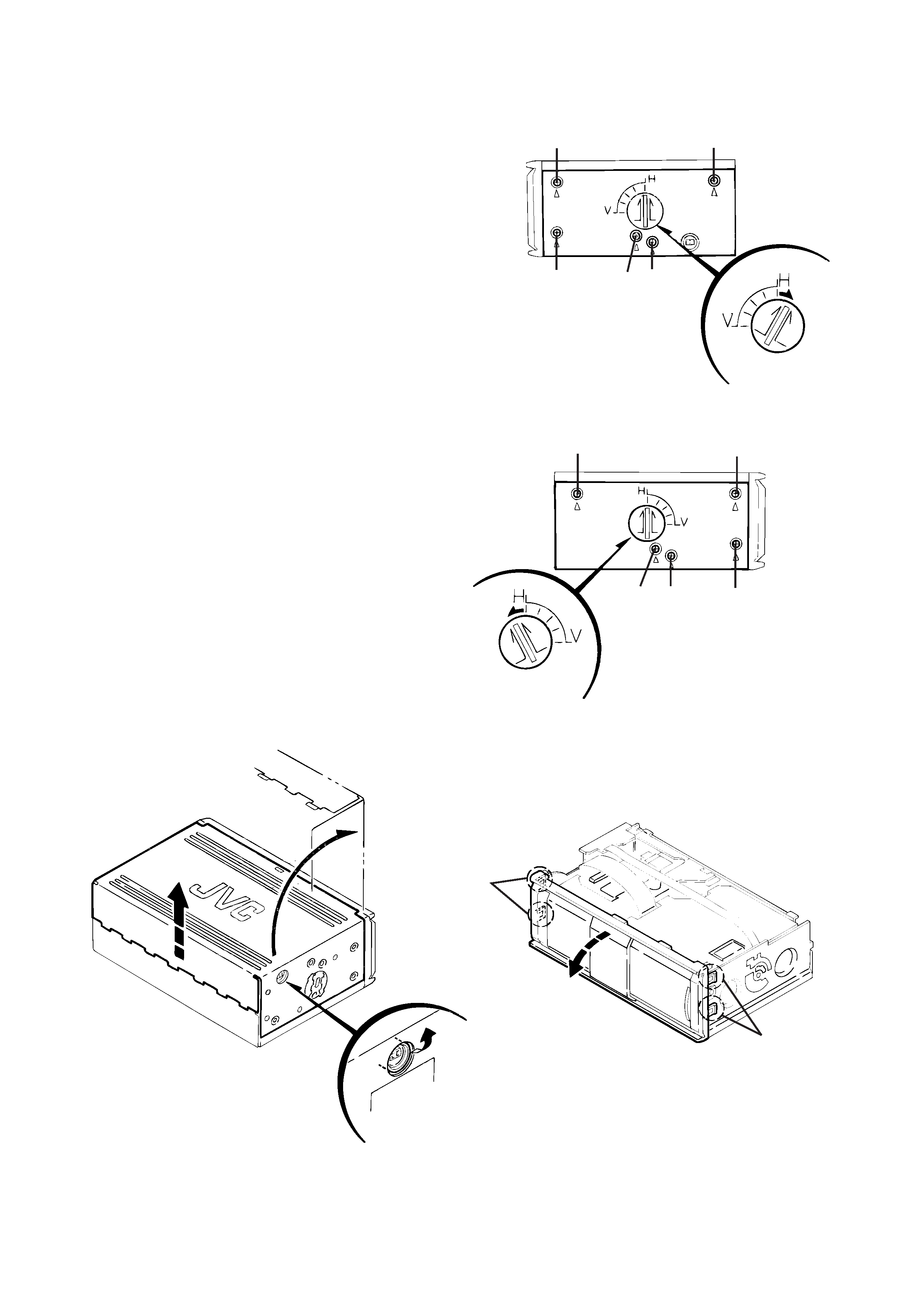
1. Remove the screw (1-a) to unlock the mounting direction
knob located on the side of the main unit.
2. Turn the mounting direction knob in the direction of the arrow
using a coin, etc. to remove it. (The knob can be removed
only when it is set to this position.)
3. Remove the four top cover fixing screws (1) at the triangle
(A) marks on the side of the main unit. (Perform the same
operation on both sides.)
4. Turn the unit upside down so the bottom surface is facing
upward.
5. Lift the rear edge of the bottom cover slightly and lift the side
by grasping the DIN jack section on the side panel, then
turn it toward the front (raise upward) to remove the bottom
cover.
6. Unhook the four catches located on both sides of the front
panel, and turn the front panel toward the top cover (lower
down) to remove the front panel.
Remove 1-a and
turn in the direction
of the arrow.
Fig. 1
Fig. 2
Fig. 3
Fig. 4
*Exterior Section
Removing the Bottom Cover and Front Panel
Assembly
1
1
1
1
1-a
1
1
1
1
1-a
Remove 1-a and
turn in the
direction of the
arrow
Unhook catches
Unhook catches
The front panel can be
separated by raising the
cover.
Slightly lift the
jack section to
remove.
Disassembling Procedures
Perform operations according to the items to be disassembled.
Replacement of the Pickup
1. After removing the exterior (top and bottom)...
2. Proceed to the "Pickup Replacement" section.
3. When applying grease, refer to the Exploded View.
Use new grease.
Mechanism Section
1. Remove the exterior (required section only).
2. The mechanism section is designed so that each unit can be
removed separately.
3. When re-assembling, refer to the assembling precautions.
(Use new grease when applying grease.)
Removal of Main Parts
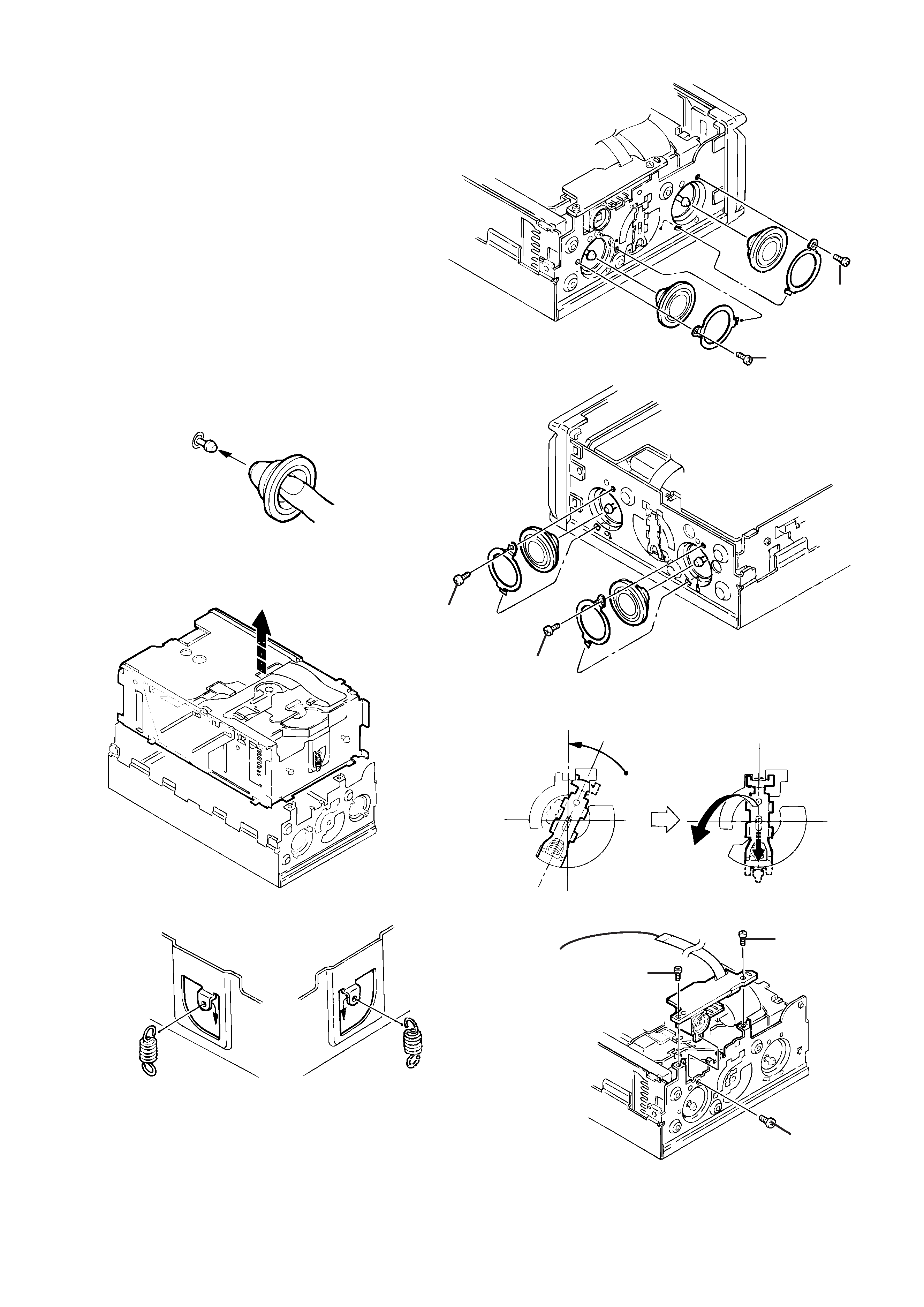
Removing the Top Cover
1. Remove the four damper bracket fixing screws (2) to remove
the damper brackets.
2. Pull out the dampers, being careful not to damage them.
When re-attaching a damper, insert your finger to push out the
center of the damper to mount it on the damper shaft, as
shown in Fig. 6-1.
3. Turn the damper spring bracket toward the top at a right angle
as shown in Fig. 7, then push down the lower side of the
damper spring bracket to lift it off.
4. Remove the three fixing screws (3) and (4) on the DIN jack
PCB assembly.
5. Lift the changer unit upward.
6. Remove the damper springs from the mechanism chassis if
required. To reassemble, refer to the diagram below.
Fig. 5
Fig 6
Fig. 6-1
Fig. 7
Fig. 8
Fig. 8-1
Fig. 9
Apply alcohol to the shaft then
immediately attach the damper. (After
attaching, check that the shaft is
correctly inserted.)
Push out with your
finger before
attaching
Turn to the top position (at a right angle),
then push down to lift off.
Lift the changer unit upward
How to Attach the Damper Springs
Silver
(mechanism side)
Black
(magazine side)
Mechanism
Chassis
Remove the flexible ribbon
wire if required
2
2
2
2
4
4
3
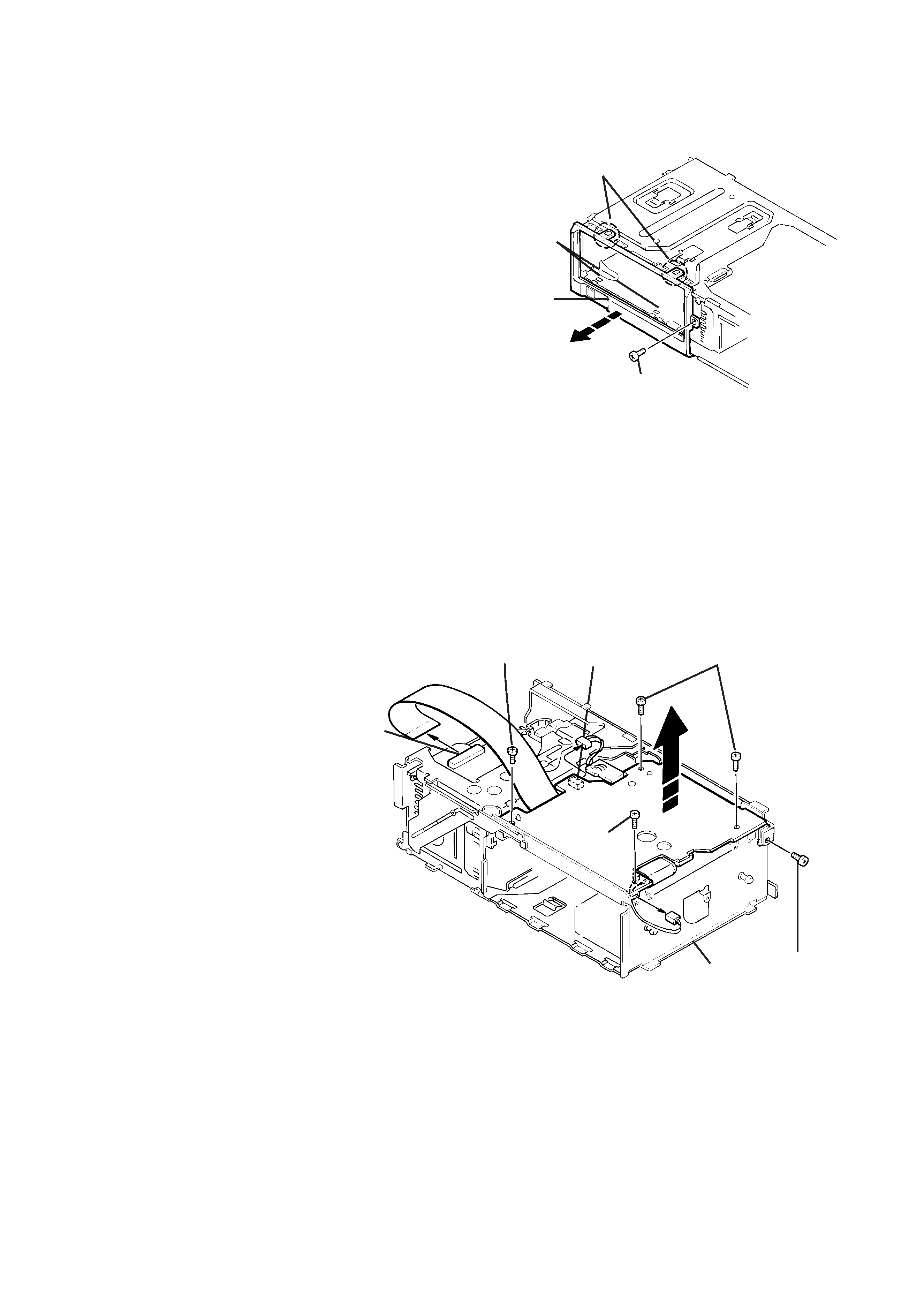
Removing the Fittings
Removing the Main PCB Assembly
1. Remove the fixing screw (5).
2. Unhook the two catches (a) on the top edge of the fitting,
then unhook the catches (b) at the left/right bottom edges.
1. Remove the power IC fixing screw (6).
2. Remove the four screws (7) securing the main PCB
assembly.
3. Disconnect position motor wire connector CN504 from the
main PCB assembly.
4. Disconnect sensor PCB assembly wire connector CN601
from the main PCB assembly.
5. Remove the flexible ribbon wire from CN502 on the traverse
mechanism PCB assembly.
When re-installing the PC boards, refer to the reassembling
procedures for protecting switches, etc.
Catches (a)
Catches (b)
Fitting
5
7
CN601
7
7
Fig. 10
Fig. 11
6
CN504
CN502
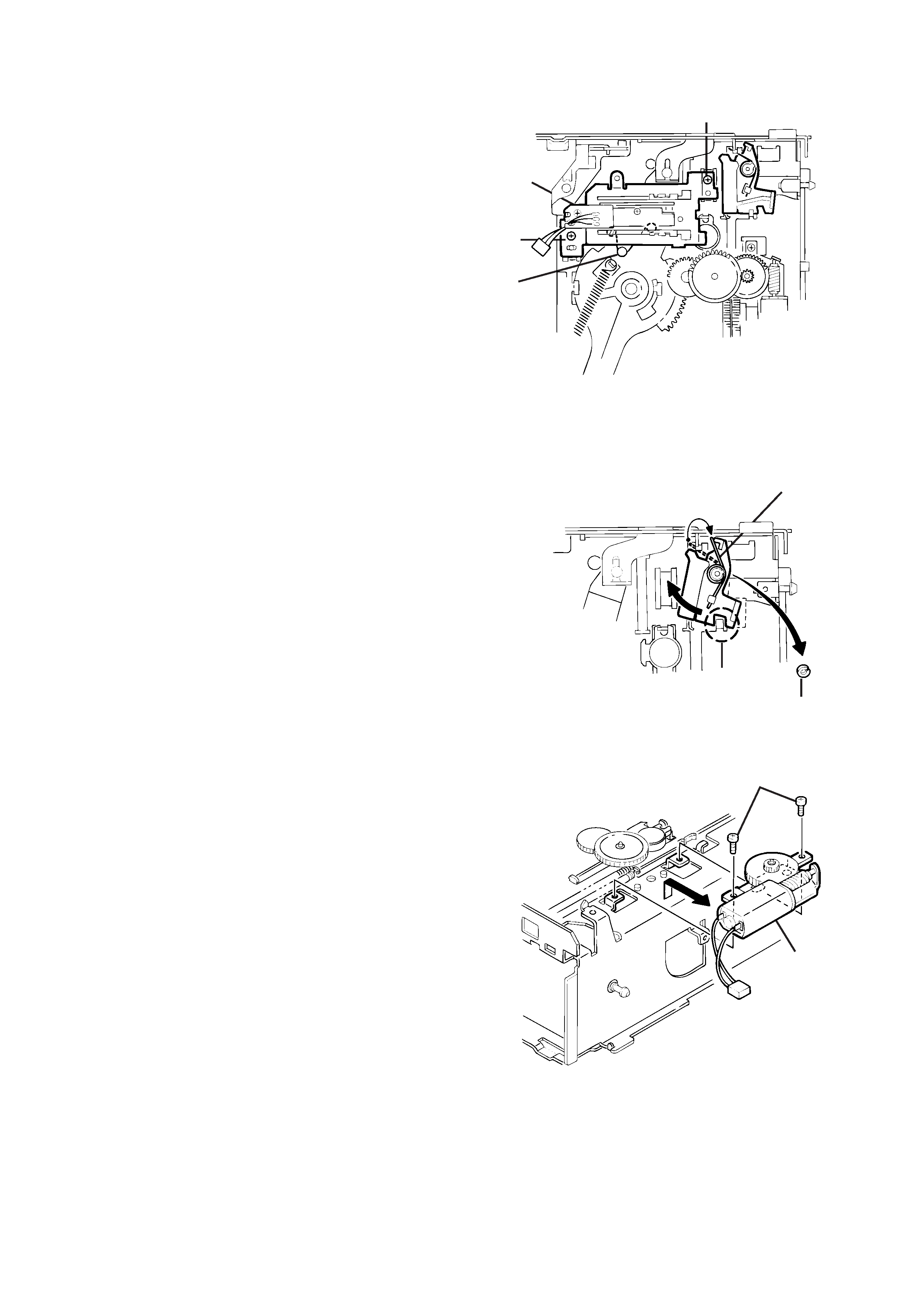
Fig. 14
Fig. 15
Fig. 16
Sensor
Assembly
1
1
a
Rear
Magazine Lock Spring
Poly-Washer (b)
c
Positioning
Motor Assembly
2
*Changer Mechanism Section
Sensor Assembly Unit
1. Remove the two screws (1) securing the sensor assembly
unit.
2. Unhook the springs on the back of the sensor assembly unit
from the holes on the chassis.
Magazine Lock Arm
1. Remove the magazine lock spring from the front side of the
chassis.
2. Remove the poly-washer (b) securing the magazine lock arm.
3. Turn the magazine lock arm in the direction of the arrow until
the notch is at the "C" position to remove it from the chassis.
Positioning Motor Assembly
1. Remove the two screws (2) securing the positioning motor.
2. Slightly lift the positioning motor assembly to remove it from
the two burrs on the chassis.