SERVICE MANUAL
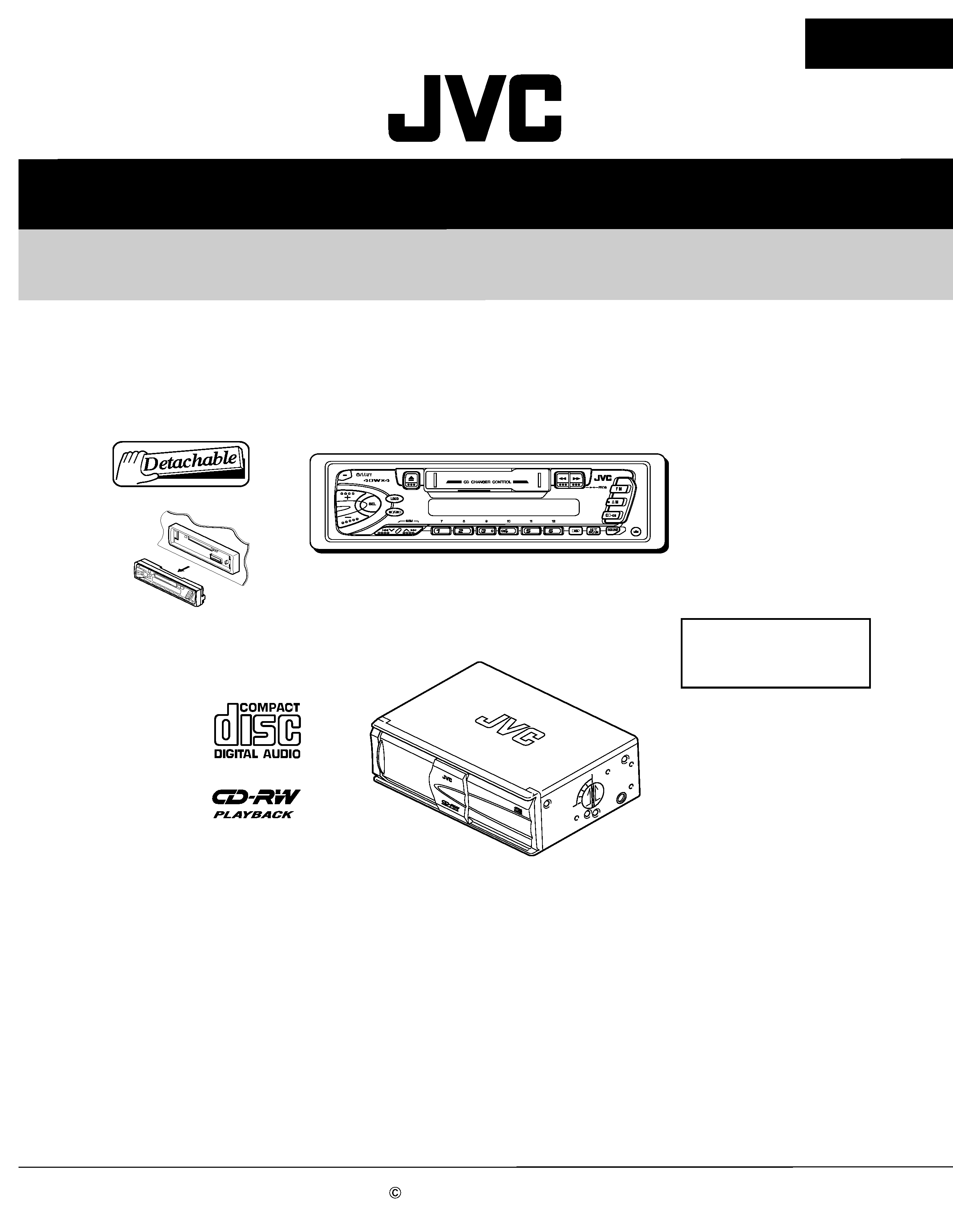
CD CHANGER SYSTEM
No.49704
Feb. 2002
COPYRIGHT
2002 VICTOR COMPANY OF JAPAN, LTD.
CH-PK202
CH-PK202
Area Suffix
KS-FX202
CD changer control receiver
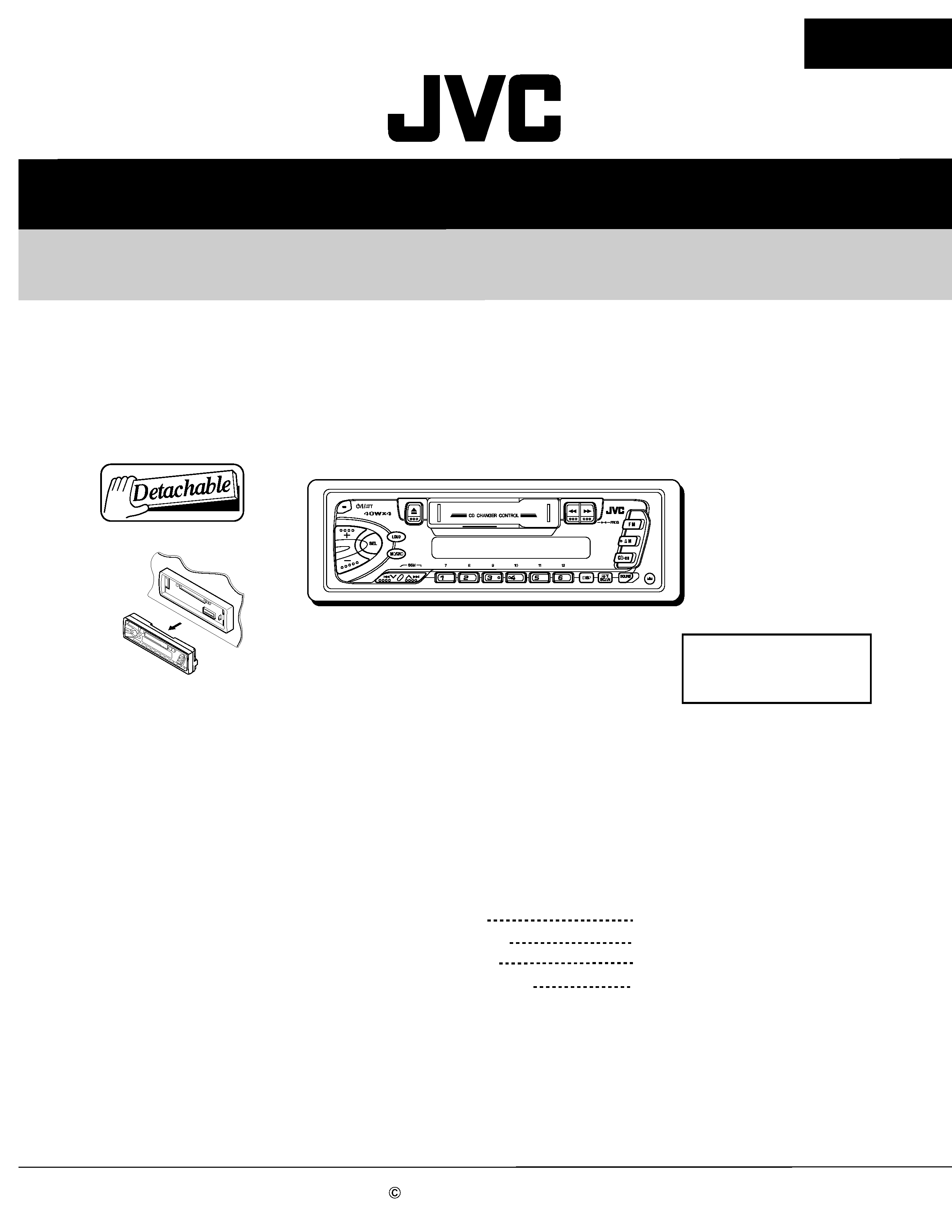
This model is combination of the CH-X500, CD Changer and the KS-FX202,
CD changer control receiver in one packing.
Please refer to the service manual of CH-X500(No.49698) and KS-FX202(No.49682)
for items other than this packing .
CH-X500
CD changer
E ------- Continental Europe
EX ----------- Central Europe
CO
MPA
CT
DIS
C
CHA
NG
ER
12Ð
DIS
C
CH
-X5
00
KS-FX202
CH-PK202
VICTOR COMPANY OF JAPAN, LIMITED
MOBILE ELECTRONICS DIVISION
PERSONAL & MOBILE NETWORK BUSINESS UNIT. 10-1,1Chome,Ohwatari-machi,Maebashi-city,371-8543,Japan
(No.49704)
200202
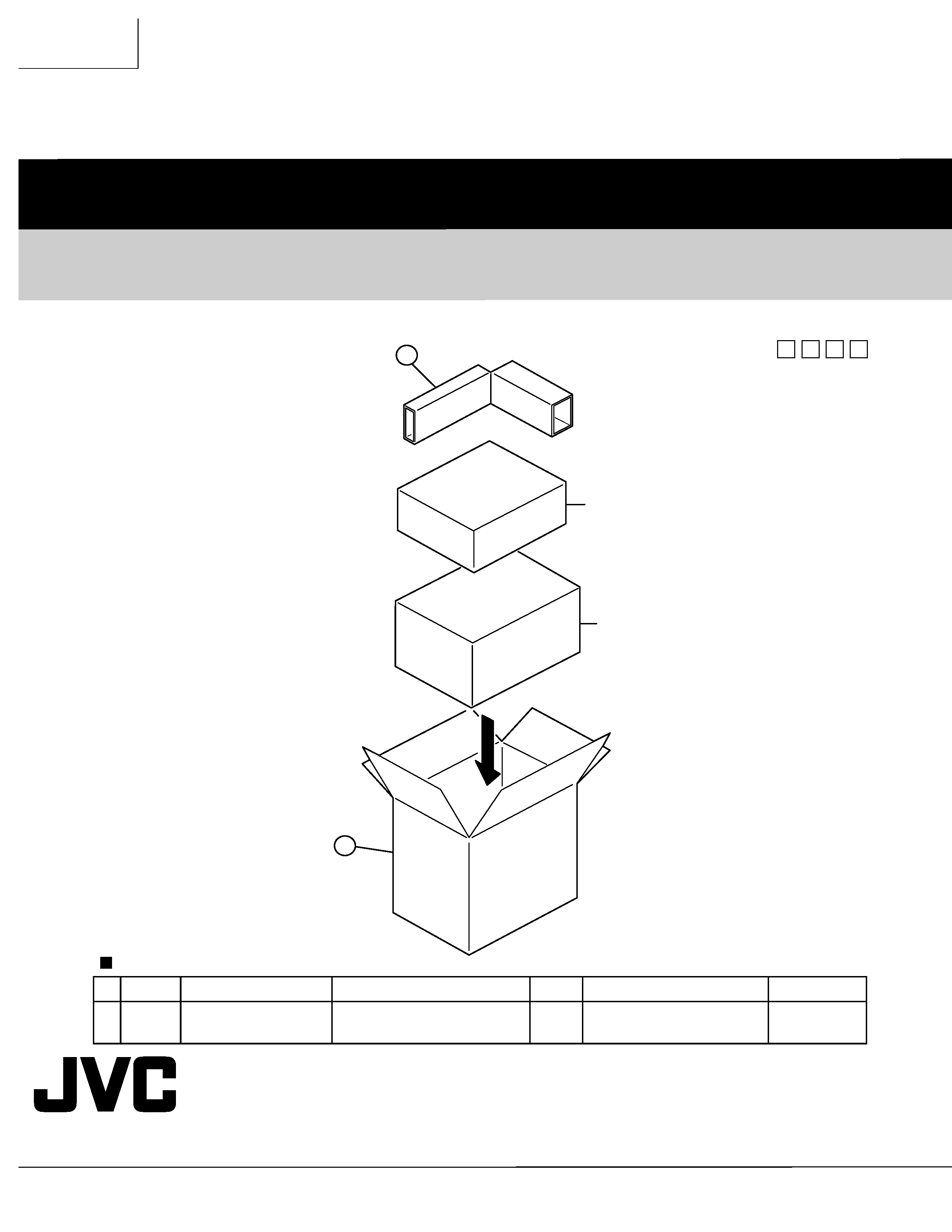
Packing materials parts list
Block No. M
M
M
3
Item
Parts number
Parts name
Area
A
Parts list (Packing)
Q'ty
Description
Block No. M3MM
P 1
LV33460-005A
PACKING CASE
1
P 2
FSPK3014-001
SPACER
1
P1
P2
KS-FX202
CH-X500
SERVICE MANUAL
CASSETTE RECEIVER
No.49682
Jan. 2002
COPYRIGHT
2002 VICTOR COMPANY OF JAPAN, LTD.
KS-FX202
KS-FX202
Area Suffix
E -------- Continental Europe
EX ------------Central Europe
KS-FX202
Contents
Safety precaution
Disassembly method
Adjustment method
1-2
1-3
1-12
1-16
Description of major ICs

KS-FX202
1-2
!
Burrs formed during molding may be left over on some parts of the chassis. Therefore,
pay attention to such burrs in the case of preforming repair of this system.
Safety precaution
KS-FX202
1-3
Fig. 3
d
Front chassis
a
a
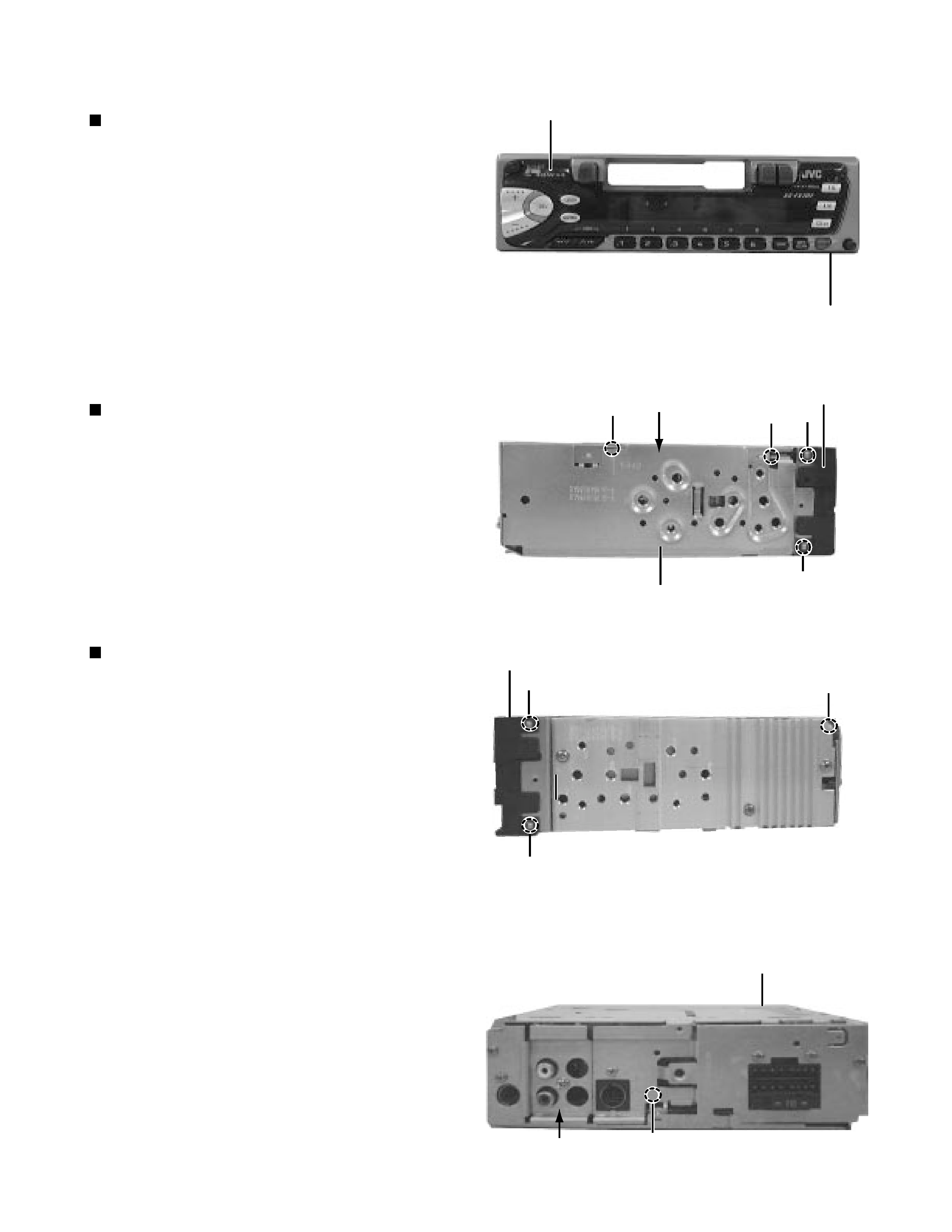
Disassembly method
Detaching the front panel unit
( See Fig.1 )
Push the Release button in the direction of arrow to
detach the front panel unit.
Removing the front chassis
( See Fig. 2 and 3 )
Disengage the four tabs ( a ) in the right and left sides of
unit and pull the front chassis forward to remove it.
Removing the bottom cover
( See Fig. 2 to 4 )
1. Removie the front chassis.
2.
Turn the unit up side down.
3.
Insert the screwdriver to the four engagements
( b, c, d, f ) .
4.
Turn the screwdriver and remove the bottom
cover.
Fig. 1
Push the release button
Front panel unit
a
a
Fig. 2
Top chassis
Front chassis
Bottom cover
b
c
Fig. 4
f
Bottom cover
Rear panel