SERVICE MANUAL
No. HV005
July 2004
COPYRIGHT © 2004 Victor Company of Japan, Limited
Due to a software update the model name on the serial number plate of the BR-DV3000U has
been changed to BR-DV3000U(A) for after the serial number listed below.
This service manual only describes the matters that are difference from the BR-DV3000U.
On servicing, refer to the service manual of BR-DV3000U/E (No. 9391) together with this
manual. The differences are as described in section 1.
BR-DV3000U(A): Serial number xxx31941 and after.
BR-DV3000U(A)
DV VIDEO CASSETTE RECORDER
Printed in Japan
(S)-A.I
Victor Company of Japan, Limited
1. SECTION1 SERVICE CAUTIONS
1.1 Difference between BR-DV3000U(A) and BR-DV3000U
(1)
Software for each CPU
Board
Symbol
BR-DV3000(A)
Latest version for BR-DV3000
Remarks
MAIN
IC2001
PLSL1144-V1-05
PLSL1144-V1-04
SYS
DV/CPU
IC302
PLSL1141-V3-02
PLSL1141-V3-01
MSD
(3)
PACKING
Page
Ref. No.
BR-DV3000U(A)
BR-DV3000U
Remarks
7-1
-
LLT0055-001A-H
None
Additional Instruction Sheet
(2)
An addition function
The CLOSED CAPTION function is added to BR-DV3000(A) and subsequent model.
The item "CC MASK" which turns off the CLOSED CAPTION function was added to the service menu.
1.2 Additional Instruction Sheet
INSTRUCTIONS (Supplement)
Closed caption
Closed caption data is embedded onto the analog video
input signal (composite or Y/C) or DV input signal, it can
be recorded onto the tape.
When the tape with embedded closed caption is played
back by this unit, it outputs on the analog video signal
(composite or Y/C) or DV signal.
Note
While inputing closed caption data when input select is set to DV, its
data may not be decoded correctly on the monitor output signal through
analog video interface.
But, this signal can be recorded onto the tape correctly.
LLT0055-001A-H
(BR-DV3000U)
SERVICE MANUAL
BR-DV3000U/E
DV VIDEO CASSETTE RECORDER
No. 9391
November 2002
COPYRIGHT © 2002 VICTOR COMPANY OF JAPAN, LTD.
Printed in Japan
(S)-I.A/O.S/A.I/GEN
VICTOR COMPANY OF JAPAN, LIMITED
100% recycled paper
BR-DV3000U/E
No.
9391

INSTRUCTIONS
SECTION 1 SERVICE CAUTIONS AND DISASSEMBLY
1.1 CONSTRUCTION OF THE MAIN BOARD ................................ 1-1
1.2 HOW TO REMOVE THE OUTER COVER ................................. 1-2
1.2.1 Top cover ............................................................................ 1-2
1.2.2 Bottom cover ..................................................................... 1-2
1.2.3 Front panel ......................................................................... 1-2
1.3 HOW TO REPLACE THE FUSE ................................................ 1-2
1.4 HOW TO EXAMINE THE BOARDS .......................................... 1-3
1.4.1 MAIN board assembly ....................................................... 1-3
1.4.2 MDA/DC board assembly .................................................. 1-3
1.4.3 DV/CPU board assembly .................................................... 1-3
1.4.4 FRONT board assembly ..................................................... 1-4
1.5 HOW TO REMOVE THE MECHANISM UNIT .......................... 1-4
1.6 HOW TO REMOVE THE MECHANISM ASSEMBLY ................ 1-5
1.7 HOW TO TAKE OUT THE CASSETTE TAPE
IN CASE OF EMERGENCY ................................................ 1-6
1.8 SERVICE MENU ....................................................................... 1-7
1.8.1 Usage procedure ................................................................ 1-7
1.8.2 VTR 1 menu ....................................................................... 1-8
1.8.3 VTR 2 menu ....................................................................... 1-8
1.8.4 VTR 3 menu ....................................................................... 1-9
1.8.5 DIP switch menu ............................................................... 1-9
1.8.6 HOUR METER menu ....................................................... 1-10
1.8.7 ERROR HISTORY menu .................................................. 1-11
1.8.8 OTHERS menu ................................................................. 1-15
1.8.9 CPU version menu ........................................................... 1-16
1.8.10 EEP-ROMS ..................................................................... 1-16
1.8.11 Real-time clock ............................................................... 1-17
SECTION 2 MECHANICAL ADJUSTMENTS
2.1 BEFORE ADJUSTMENTS ........................................................ 2-1
2.1.1 Precautions ........................................................................ 2-1
2.1.2 Measuring instruments required for adjustments ............. 2-1
2.1.3 Equipment required for adjustments ................................. 2-1
2.2 DISASSEMBLY/ASSEMBLY OF THE MECHANISM ................ 2-2
2.2.1 Mechanism position for disassembly/assembly ................ 2-2
2.2.2 Mode transition .................................................................. 2-2
2.3 MECHANISM TIMING CHART ................................................. 2-3
2.4 MAINTENANCE AND INSPECTION OF MAJOR PARTS ........... 2-4
2.4.1 Layout of Major Parts ......................................................... 2-4
2.4.2 Maintenance/inspection table ............................................ 2-5
2.4.3 Cleaning ............................................................................. 2-6
2.4.4 Oiling and Greasing ............................................................ 2-6
2.5 PERIODICAL MAINTENANCE .................................................. 2-7
2.6 REPLACEMENT OF MAJOR PARTS ........................................ 2-8
2.7 GUIDE ROLLER REPLACEMENT METHOD .......................... 2-24
2.8 TORQUE ADJUSTMENT ........................................................ 2-25
2.9 INTERCHANGEABILITY ADJUSTMENT ................................. 2-27
2.9.1 Interchangeabilty adjustment flow chart .......................... 2-27
2.9.2 Tape Transport Restriction ............................................... 2-28
2.9.3 Interchangeability adjustment .......................................... 2-29
SECTION 3 ELECTRICAL ADJUSTMENTS
3.1 PRECAUTIONS FOR ELECTRICAL ADJUSTMENTS ............... 3-1
3.1.1 Measuring instruments and Tools required for
adjustments ....................................................................... 3-1
3.1.2 Alignment tape specifications ............................................ 3-1
3.1.3 Signals required for adjustments ....................................... 3-1
3.1.4 Notes for adjustments ....................................................... 3-2
3.1.5 Adjustment menu .............................................................. 3-2
3.2 DVC UNIT ADJUSTMENTS ...................................................... 3-4
3.3 VIDEO SYSTEM ADJUSTMENTS ............................................ 3-8
3.4 REWRITE BOARD SCHEMATIC DIAGRAM ........................... 3-23
SECTION 4 CHARTS AND DIAGRAMS
4.1 INDEX TO PAGES OF MAIN BOARDS AND
CIRCUIT BOARD LOCATION ................................................... 4-4
4.1.1 Circuit board location ......................................................... 4-4
4.2 SYSTEM CONTROL BLOCK DIAGRAM ................................... 4-5
4.3 VIDEO BLOCK DIAGRAM ........................................................ 4-6
4.4 AUDIO BLOCK DIAGRAM ....................................................... 4-7
4.5 OVERALL WIRING DIAGRAM ................................................. 4-8
4.6 DV UNIT OVERALL WIRING DIAGRAM .................................. 4-9
4.7 MAIN SCHEMATIC DIAGRAM 1/6 ......................................... 4-10
· MAIN SCHEMATIC DIAGRAM 2/6 ......................................... 4-11
· MAIN SCHEMATIC DIAGRAM 3/6 ......................................... 4-12
· MAIN SCHEMATIC DIAGRAM 4/6 ......................................... 4-13
· MAIN SCHEMATIC DIAGRAM 5/6 ......................................... 4-14
· MAIN SCHEMATIC DIAGRAM 6/6 ......................................... 4-15
4.8 MAIN CIRCUIT BOARD .......................................................... 1-16
4.9 DV/CPU SCHEMATIC DIAGRAM 1/4 ..................................... 4-18
· DV/CPU SCHEMATIC DIAGRAM 2/4 ..................................... 4-19
· DV/CPU SCHEMATIC DIAGRAM 3/4 ..................................... 4-20
· DV/CPU SCHEMATIC DIAGRAM 4/4 ..................................... 4-21
4.10 DV/CPU CIRCUIT BOARD ..................................................... 4-22
4.11 MDA/DC CIRCUIT BOARD ................................................... 4-23
4.12 MDA/DC SCHEMATIC DIAGRAM 1/4 ................................... 4-24
· MDA/DC SCHEMATIC DIAGRAM 2/4 ................................... 4-25
· MDA/DC SCHEMATIC DIAGRAM 3/4 ................................... 4-26
· MDA/DC SCHEMATIC DIAGRAM 4/4 ................................... 4-27
4.13 FDM (FRONT, DV, CONN & MIC)
SCHEMATIC DIAGRAM ........................................................ 4-28
4.14 FDM (FRONT, DV, CONN & MIC) CIRCUIT BOARDS ........... 4-29
4.15 MECHA & MECHA CONN SCHEMATIC DIAGRAMS ........... 4-30
4.16 MECHA & MECHA CONN CIRCUIT BOARDS ...................... 4-31
4.17 IC BLOCK DIAGRAMS .......................................................... 4-33
SECTION 5 EXPLODED VIEW AND PARTS LIST
5.1 CABINET & CHASSIS ASSEMBLY
M2 .................................... 5-3
5.2 MECHANISM ASSEMBLY
M3 ................................................ 5-4
SECTION 6 ELECTRICAL PARTS LIST
6.1 MAIN BOARD ASSEMBLY PARTS LIST
01 ........................... 6-2
6.2 FRONT BOARD ASSEMBLY PARTS LIST
02 ....................... 6-11
6.3 DVCONN BOARD ASSEMBLY PARTS LIST
03 ................... 6-11
6.4 MIC BOARD ASSEMBLY PARTS LIST
04 ............................ 6-11
6.5 DV/CPU BOARD ASSEMBLY PARTS LIST
11...................... 6-12
6.6 MDA/DC BOARD ASSEMBLY PARTS LIST
12 .................... 6-15
6.7 MECHA BOARD ASSEMBLY PARTS LIST
13 ..................... 6-18
6.8 MECHA CONN BOARD ASSEMBLY PARTS LIST
14 .......... 6-18
SECTION 7 PACKING
7.1 PACKING ASSEMBLY
M1 ...................................................... 7-1
SECTION 8 TECHNICAL DESCRIPTION
8.1 PRODUCT OUTLINE ................................................................ 8-1
8.2 MECHANISM ........................................................................... 8-1
8.2.1 Comparison with previous mechanism .............................. 8-1
8.2.2 Regarding standard cassette ............................................. 8-1
8.2.3 Cassette housing operation outline ................................... 8-2
8.2.4 Switches ............................................................................ 8-4
8.2.5 Reel motor ......................................................................... 8-4
8.2.6 Tension ............................................................................... 8-4
8.2.7 Mode sensor ...................................................................... 8-5
8.3 SYSTEM CONTROL ................................................................. 8-5
8.3.1 Outline ............................................................................... 8-5
8.3.2 Communication specifications ........................................... 8-5
8.3.3 Communication timing ....................................................... 8-5
8.3.4 SYSCON (IC2001) CPU port functions .............................. 8-6
8.3.5 MSD CPU (IC302) port functions ....................................... 8-8
8.3.6 RS-422A command list .................................................... 8-14
TABLE OF CONTENTS
Section
Title
Page
Section
Title
Page
Important Safety Precautions
Important Safety Precautions
Prior to shipment from the factory, JVC products are strictly inspected to conform with the recognized product safety and electrical codes
of the countries in which they are to be sold. However, in order to maintain such compliance, it is equally important to implement the
following precautions when a set is being serviced.
Fig.1
1. Locations requiring special caution are denoted by labels and
inscriptions on the cabinet, chassis and certain parts of the
product. When performing service, be sure to read and com-
ply with these and other cautionary notices appearing in the
operation and service manuals.
2. Parts identified by the
symbol and shaded (
) parts are
critical for safety.
Replace only with specified part numbers.
Note: Parts in this category also include those specified to com-
ply with X-ray emission standards for products using
cathode ray tubes and those specified for compliance
with various regulations regarding spurious radiation
emission.
3. Fuse replacement caution notice.
Caution for continued protection against fire hazard.
Replace only with same type and rated fuse(s) as specified.
4. Use specified internal wiring. Note especially:
1) Wires covered with PVC tubing
2) Double insulated wires
3) High voltage leads
5. Use specified insulating materials for hazardous live parts.
Note especially:
1) Insulation Tape
3) Spacers
5) Barrier
2) PVC tubing
4) Insulation sheets for transistors
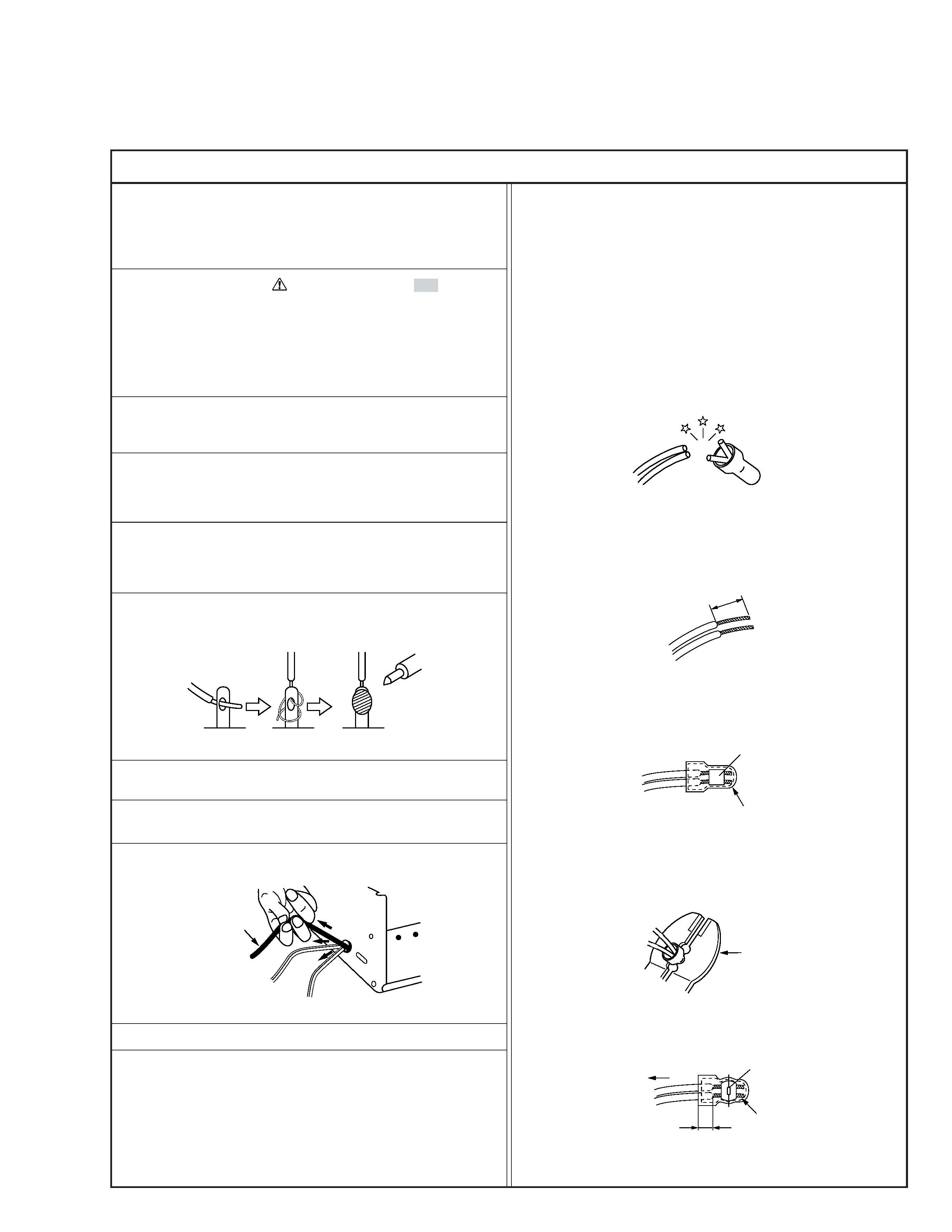
6. When replacing AC primary side components (transformers,
power cords, noise blocking capacitors, etc.) wrap ends of
wires securely about the terminals before soldering.
Power cord
Fig.2
10. Also check areas surrounding repaired locations.
11. Products using cathode ray tubes (CRTs)
In regard to such products, the cathode ray tubes themselves,
the high voltage circuits, and related circuits are specified for
compliance with recognized codes pertaining to X-ray emission.
Consequently, when servicing these products, replace the cath-
ode ray tubes and other parts with only the specified parts.
Under no circumstances attempt to modify these circuits.
Unauthorized modification can increase the high voltage value
and cause X-ray emission from the cathode ray tube.
12. Crimp type wire connector
In such cases as when replacing the power transformer in sets
where the connections between the power cord and power
transformer primary lead wires are performed using crimp type
connectors, if replacing the connectors is unavoidable, in or-
der to prevent safety hazards, perform carefully and precisely
according to the following steps.
1) Connector part number : E03830-001
2) Required tool : Connector crimping tool of the proper type
which will not damage insulated parts.
3) Replacement procedure
(1) Remove the old connector by cutting the wires at a point
close to the connector.
Important : Do not reuse a connector (discard it).
Fig.7
cut close to connector
Fig.3
(2) Strip about 15 mm of the insulation from the ends of
the wires. If the wires are stranded, twist the strands to
avoid frayed conductors.
15 mm
Fig.4
(3) Align the lengths of the wires to be connected. Insert
the wires fully into the connector.
Connector
Metal sleeve
Fig.5
(4) As shown in Fig.6, use the crimping tool to crimp the
metal sleeve at the center position. Be sure to crimp fully
to the complete closure of the tool.
1
Precautions during Servicing
7. Observe that wires do not contact heat producing parts
(heatsinks, oxide metal film resistors, fusible resistors, etc.)
8. Check that replaced wires do not contact sharp edged or
pointed parts.
9. When a power cord has been replaced, check that 10-15 kg of
force in any direction will not loosen it.
1.25
2.0
5.5
Crimping tool
Fig.6
(5) Check the four points noted in Fig.7.
Not easily pulled free
Crimped at approx. center
of metal sleeve
Conductors extended
Wire insulation recessed
more than 4 mm