No.51748
Jul. 2000
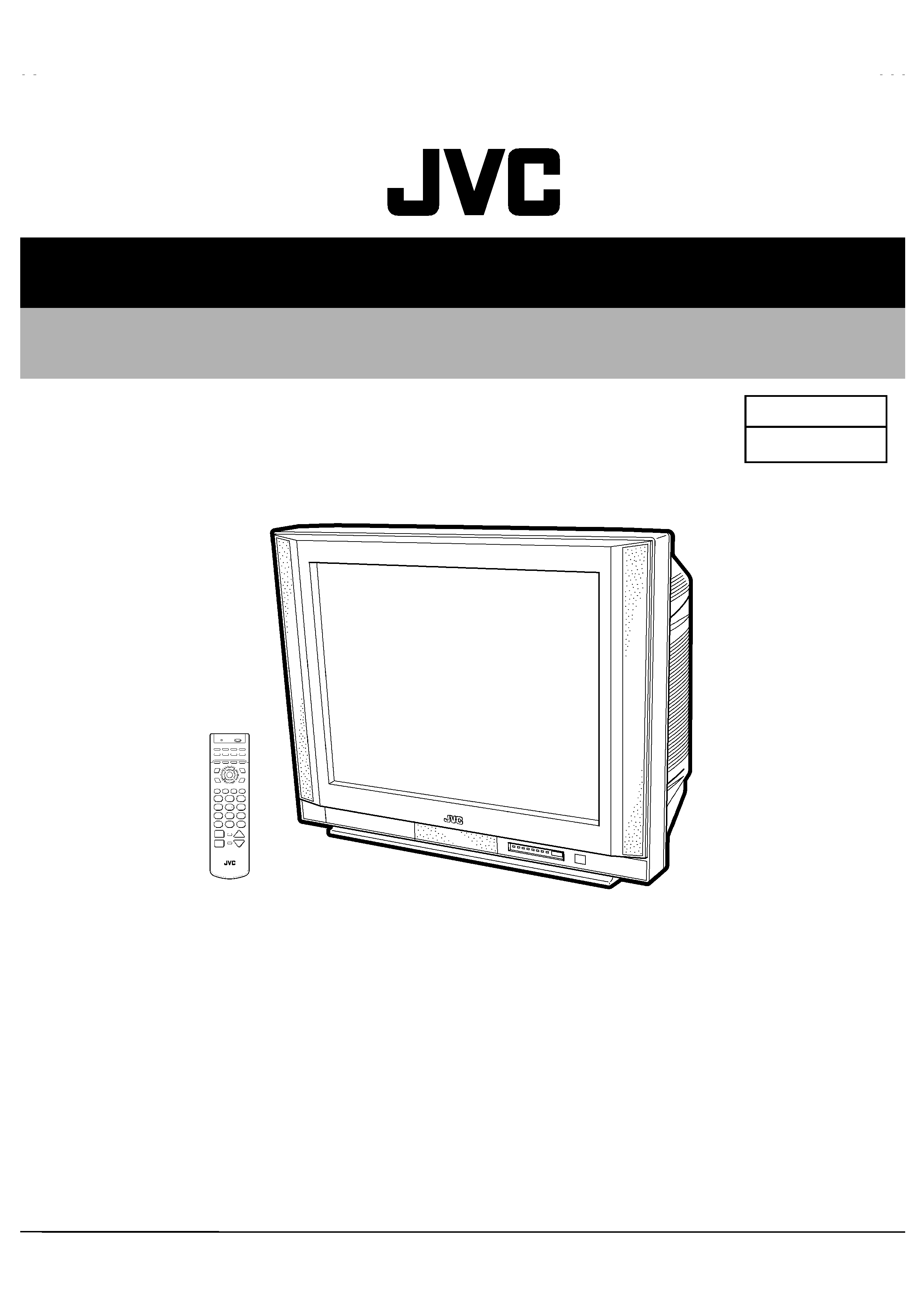
AV-RX29
1
COPYRIGHT © 2000 VICTOR COMPANY OF JAPAN, LTD.
! MAIN DIFFERENCE ITEMS
ITEMS
No.
ITEMS
AV-29RS
(No.51730)
AV-RX29(HK)
(No.51748)
Remarks
1
Tele text
FLOF(fastext) / WST
NON
2
Power plug
Round Pin type
UK pin type
3
Instruction Book
English
English & Chinese
4
Remote control unit
RM-C112
RM-C115
5
OSD Language
Eng. / Ara. / Fre. / Rus.
Eng. / Chinese
6
Main PWB
SJK-1003A-H2
SJK-1011A-H2
See next page
! DIFFERENCE PARTS LIST
···· EXPLODED VIEW PARTS LIST (Page35,36)
Model No. & Parts No.
!
!
!
!
Ref. No.
AV-29RSB
(No.51726)
AV-SX29(HK)
(No.51746)
Parts Name
Remarks
!
13
QMP40D0-200J5
QMPN050-200-E2
POWER CORD
Not Interchangeable
!
16
LC20377-001B-H
LC20377-012B-H
RATING LABEL
!
37
LC10761-002B-H
LC10761-012B-H
FRONT CABI. ASS'Y
38
LC20532-003B-H
LC20532-007B-H
DOOR
···· PACKING (Page49)
1
LC10845-006A-H
LC10845-009A-H
PACKING CASE
4
RM-C112-2H
RM-C115-2H
REMOCON UNIT
!
6
LCT0660-001B-H
LCT0813-001A-H
INST BOOK
BASIC CHASSIS
JK
SERVICE MANUAL
COLOUR TELEVISION
The following item for the AV-RX29(HK) model were changed from those of the AV-29RS model.
Therefore, this service manual describes only the items which differ from those of the AV-29RS service
manual.
For details other than those described in this manual, please refer to the AV-29RS service manual
(No.51730, Jul, 2000).
AV-RX29(HK)
AVRX29HK-H
#3
4
DP 0007
DP1054
! MAIN PWB PARTS LIST (Page38-41)
Parts Number
!
!
!
!
Ref. No.
AV-29RS(No.51730)
AV-RX29(HK)(No.51748)
Parts Name
Remarks
SJK-1003A-H2
SJK-1011A-H2
R1329
NRSA02J-102X
NRSA02J-0R0X
CHIP RESISTER
R1330
NRSA02J-472X
NRSA02J-0R0X
CHIP RESISTER
R1522
NRSA02J-153X
CHIP RESISTER
R1523
NRSA02J-103X
CHIP RESISTER
R1524
NRSA02J-152X
CHIP RESISTER
R1661
NRSA02J-103X
CHIP RESISTER
R1664
NRSA02J-562X
CHIP RESISTER
R1871
NRSA02J-102X
CHIP RESISTER
R1872-74
NRSA02J-222X
CHIP RESISTER
R1875
NRSA02J-0R0X
CHIP RESISTER
R1876
NRSA02J-102X
CHIP RESISTER
R1877
NRSA02J-393X
CHIP RESISTER
R1878-80
NRSA02J-182X
CHIP RESISTER
R1881-82
NRSA02J-181X
CHIP RESISTER
R1883
NRSA02J-102X
CHIP RESISTER
R1884
NRSA02J-181X
CHIP RESISTER
C1312
NDC21HJ-680X
C CAP.
68pF
50V
J
C1324-26
QETN1HM-105Z
E CAP.
C1334-36
NCB21HK-103X
E CAP.
0.01F
50V
K
C1871
NCB21EK-104X
CHIP C CAP.
C1872
NCB21HK-223X
CHIP C CAP.
C1873
NDC21HJ-221X
CHIP C CAP.
C1874-75
NDC21HJ-150X
CHIP C CAP.
C1876
NDC21HJ-221X
CHIP C CAP.
C1877
NCB21EK-104X
CHIP C CAP.
C1878
NCB21HK-102X
CHIP C CAP.
C1879
NDC21HJ-221X
CHIP C CAP.
C1880
QETN1AM-477Z
E CAP.
C1881
NCB21EK-104X
CHIP C CAP.
C1882
QETN1EM-476Z
E CAP.
C1883
NCB21HK-103X
CHIP C CAP.
C1884
NCB21EK-104X
CHIP C CAP.
C1885
NCB21EK-104X
CHIP C CAP.
C1886
NCB21HK-103X
CHIP C CAP.
L1871
QQL244K-4R7Z
PEAKING COIL
L1872
QQL244K-3R3Z
PEAKING COIL
D1303
MA111-X
CHIP DIODE
Q1501
2SC2412K/QR/-X
CHIP TRANSISTER
Q1613
2SA1037AK/QR/-X
SI TRANSISTER
Q1871
2SA1037AK/QR/-X
SI TRANSISTER
Q1872
2SC2412K/QR/-X
CHIP TRANSISTER
IC1701
M37280MF-173SP
M37280MF-171SP
I.C.
IC1871
ET417
I.C.
IC1872
ET211
I.C.
X1871
CE41257-001Z
X TAL
VICTOR COMPANY OF JAPAN, LIMITED
HOME AV NETWORK BUSINESS UNIT
1106 Heta, Iwai-city, Ibaraki-prefecture, 306-0698, Japan
No.51730
Jul. 2000
AV-29RS
1
COPYRIGHT © 2000 VICTOR COMPANY OF JAPAN, LTD.
AV-29RS
CONTENTS
! SPECIFICATIONS
2
OPERATING INSTRUCTIONS (APPENDIX)
1-1
! SAFETY PRECAUTIONS
3
! FEATURES
4
! FUNCTIONS
5
! SPECIFIC SERVICE INSTRUCTIONS
6
! SERVICE ADJUSTMENTS
12
STANDARD CIRCUIT DIAGRAM (APPENDIX)
2-1
! PARTS LIST
33
SERVICE MANUAL
COLOUR TELEVISION
BASIC CHASSIS
JK
No.51730
AV-29RS
2
SPECIFICATIONS
Item
CONTENTS
Dimensions ( W×
×
×
×H×
×
×
×D )
887mm×719mm×620mm
Mass
50.0kg
TV RF System
B, G, I, D, K, K1, M
Colour System
PAL, SECAM, NTSC3.58, NTSC4.43
Stereo System
A2 / NICAM (B/G, I, D/K) system
Teletext System
FLOF (Fastext), WST (World standard system)
Receiving Frequency
VHF(L)
46.25MHz168.25MHz
VHF (H)
175.25MHz463.25MHz
UHF
471.25MHz 863.25MHz
CATV
Mid(X-Z, S1-S10), Super(S11-S20), Hyper(S21-S41) bands receivable
Intermediate Frequency
VIF Carrier
38.0MHz
SIF Carrier
33.5MHz(4.5MHz), 32.5MHz(5.5MHz), 32.0MHz(6.0MHz), 31.5MHz(6.5MHz)
Colour Sub Carrier Frequency
PAL
4.43MHz
SECAM
4.40625MHz, 4.25MHz
NTSC
3.58MHz / 4.43MHz
Power Input
AC 110V240V , 50/60Hz
Power Consumption
193W(Max) / 137W(Avg)
Picture Tube
Visible size : 68cm measured diagonally
High Voltage
32.0kV±1.5kV (at zero beam current)
Speaker & Audio Output
Open dome speaker
10W+10W, 10cm round×2
Video Audio Input terminals
S-Video
Y : 1V(p-p) positive (Negative sync provided, when terminated with 75)
C : 0.286V(p-p) (Burst signal, when terminated with 75)
Video
1V(p-p) 75(RCA pin jack)
Video1
Audio(L/R)
500mV(rms) (-4dBs), High impedance (RCA pin jack)
Video
1V(p-p) 75(RCA pin jack)
Video2
Audio(L/R)
500mV(rms) (-4dBs), High Impedance (RCA pin jack)
Video/Y
V : Composite video 1V(p-p) 75(RCA pin jack)
Y : Component video 1V(p-p) 75(RCA pin jack)
Cb
Component video B-Y 0.7V(p-p) 75(RCA pin jack)
Cr
Component video R-Y 0.7V(p-p) 75(RCA pin jack)
Video3
Audio(L/R)
500mV(rms) (-4dBs), High Impedance (RCA pin jack)
S-Video
Y : 1V(p-p) positive (Negative sync provided, when terminated with 75)
C : 0.286V(p-p) (Burst signal, when terminated with 75)
Video
1V(p-p) 75(RCA pin jack)
Video4
(Front terminal)
Audio(L/R)
500mV(rms) (-4dBs), High impedance (RCA pin jack)
Video Audio Output terminal
Video
1V(p-p) 75(RCA pin jack)
Audio(L/R)
500mV(rms) (-4dBs), High Impedance (RCA pin jack)
Aerial Input Term
75unbalanced, Coaxial
Headphone jack
Stereo mini jack (3.5mm )
AV Compu Link terminal
AV Compu Link, mini jack (3.5mm )
Remote Control Unit
RM-C112 (AAA/R03 dry battery×2)
Design & specifications are subject to change without notice.
No.51730
AV-29RS
3
SAFETY PRECAUTIONS
1.
The design of this product contains special hardware, many
circuits and components specially for safety purposes. For
continued protection, no changes should be made to the original
design unless authorized in writing by the manufacturer.
Replacement parts must be identical to those used in the original
circuits. Service should be performed by qualified personnel
only.
2.
Alterations of the design or circuitry of the products should not be
made. Any design alterations or additions will void the
manufacturer's warranty and will further relieve the manufacturer
of responsibility for personal injury or property damage resulting
therefrom.
3.
Many electrical and mechanical parts in the products have
special safety-related characteristics. These characteristics are
often not evident from visual inspection nor can the protection
afforded by them necessarily be obtained by using replacement
components rated for higher voltage, wattage, etc. Replacement
parts which have these special safety characteristics are
identified in the parts list of Service manual. Electrical
components having such features are identified by shading
on the schematics and by (!
!
!
!) on the parts list in Service
manual. The use of a substitute replacement which does not
have the same safety characteristics as the recommended
replacement part shown in the parts list of Service manual may
cause shock, fire, or other hazards.
4.
Don't short between the LIVE side ground and ISOLATED
(NEUTRAL) side ground or EARTH side ground when
repairing.
Some model's power circuit is partly different in the GND. The
difference of the GND is shown by the LIVE : (") side GND, the
ISOLATED(NEUTRAL) : (#) side GND and EARTH : ($) side
GND.
Don't
short
between
the
LIVE
side
GND
and
ISOLATED(NEUTRAL) side GND or EARTH side GND and
never measure with a measuring apparatus (oscilloscope etc.)
the LIVE side GND and ISOLATED(NEUTRAL) side GND or
EARTH side GND at the same time.
If above note will not be kept, a fuse or any parts will be broken.
5.
If any repair has been made to the chassis, it is recommended
that the B1 setting should be checked or adjusted (See
ADJUSTMENT OF B1 POWER SUPPLY).
6.
The high voltage applied to the picture tube must conform with
that specified in Service manual. Excessive high voltage can
cause an increase in X-Ray emission, arcing and possible
component damage, therefore operation under excessive high
voltage conditions should be kept to a minimum, or should be
prevented. If severe arcing occurs, remove the AC power
immediately and determine the cause by visual inspection
(incorrect installation, cracked or melted high voltage harness,
poor soldering, etc.). To maintain the proper minimum level of
soft X-Ray emission, components in the high voltage circuitry
including the picture tube must be the exact replacements or
alternatives approved by the manufacturer of the complete
product.
7.
Do not check high voltage by drawing an arc. Use a high voltage
meter or a high voltage probe with a VTVM. Discharge the
picture tube before attempting meter connection, by connecting
a clip lead to the ground frame and connecting the other end of
the lead through a 10k
! 2W resistor to the anode button.
8.
When service is required, observe the original lead dress. Extra
precaution should be given to assure correct lead dress in the
high voltage circuit area. Where a short circuit has occurred,
those components that indicate evidence of overheating should
be replaced. Always use the manufacturer's replacement
components.
9.
Isolation Check
(Safety for Electrical Shock Hazard)
After re-assembling the product, always perform an isolation
check on the exposed metal parts of the cabinet (antenna
terminals, video/audio input and output terminals, Control knobs,
metal cabinet, screw
"heads, earphone jack, control shafts, etc.)
to be sure the product is safe to operate without danger of
electrical shock.
(1) Dielectric Strength Test
The isolation between the AC primary circuit and all metal parts
exposed to the user, particularly any exposed metal part having a
return path to the chassis should withstand a voltage of 3000V
AC (r.m.s.) for a period of one second.
(. . . . Withstand a voltage of 1100V AC (r.m.s.) to an appliance
rated up to 120V, and 3000V AC (r.m.s.) to an appliance rated
200V or more, for a period of one second.)
This method of test requires a test equipment not generally found
in the service trade.
(2) Leakage Current Check
Plug the AC line cord directly into the AC outlet (do not use a line
isolation transformer during this check.). Using a "Leakage
Current Tester", measure the leakage current from each exposed
metal part of the cabinet, particularly any exposed metal part
having a return path to the chassis, to a known good earth
ground (water pipe, etc.). Any leakage current must not exceed
0.5mA AC (r.m.s.).
However, in tropical area, this must not exceed 0.2mA AC
(r.m.s.).
"
"
"
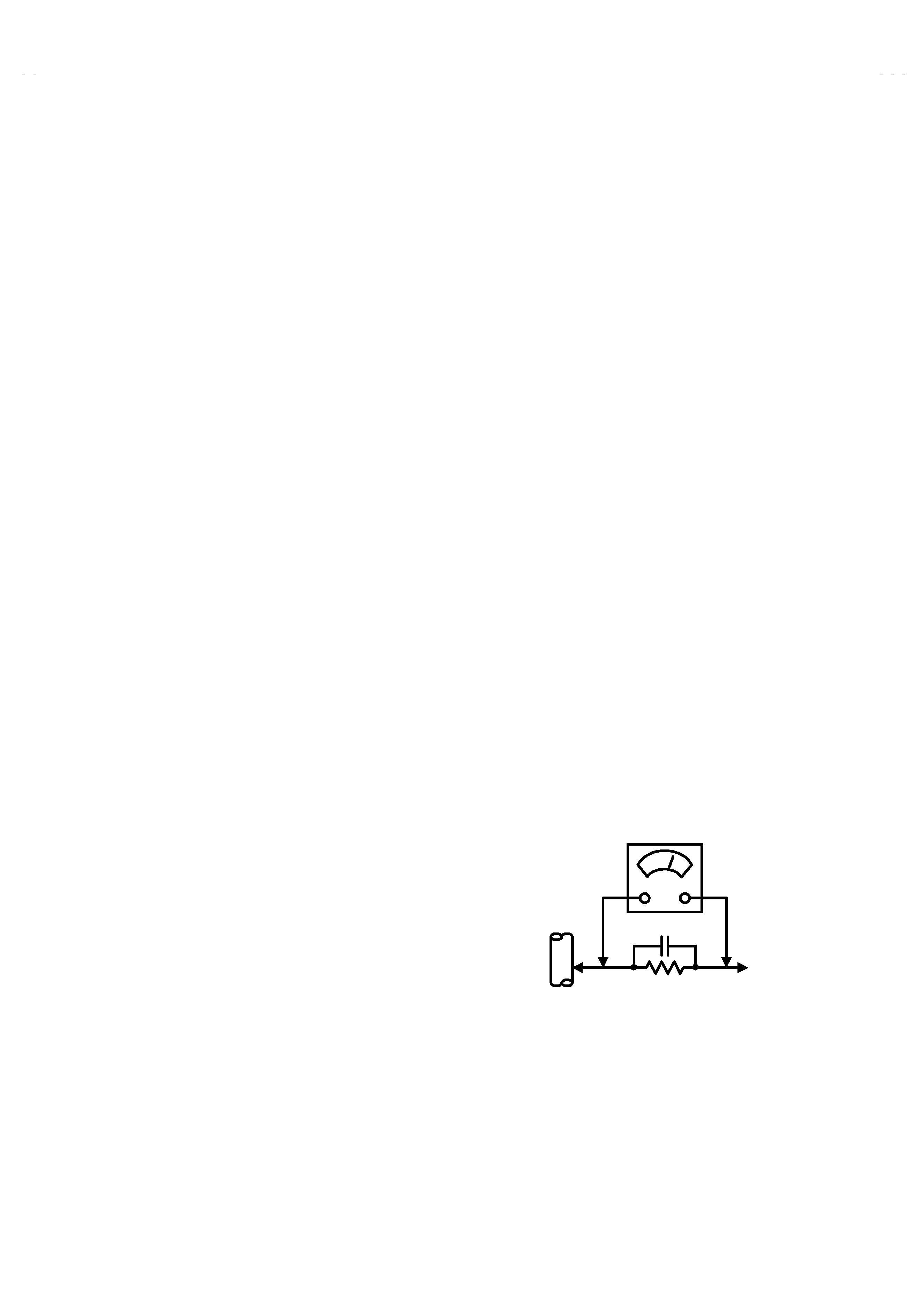
" Alternate Check Method
Plug the AC line cord directly into the AC outlet (do not use a line
isolation transformer during this check.). Use an AC voltmeter
having 1000 ohms per volt or more sensitivity in the following
manner. Connect a 1500
! 10W resistor paralleled by a 0.15#F
AC-type capacitor between an exposed metal part and a known
good earth ground (water pipe, etc.). Measure the AC voltage
across the resistor with the AC voltmeter. Move the resistor
connection to each exposed metal part, particularly any exposed
metal part having a return path to the chassis, and measure the
AC voltage across the resistor. Now, reverse the plug in the AC
outlet and repeat each measurement. Any voltage measured
must not exceed 0.75V AC (r.m.s.).
This corresponds to 0.5mA
AC (r.m.s.).
However, in tropical area, this must not exceed 0.3V AC (r.m.s.).
This corresponds to 0.2mA AC (r.m.s.).
0.15F AC-TYPE
1500 ! 10W
GOOD EARTH GROUND
PLACE THIS PROBE
ON EACH EXPOSED
METAL PART
AC VOLTMETER
(HAVING 1000 !/V,
OR MORE SENSITIVITY)