SERVICE MANUAL
COPYRIGHT © 2003 VICTOR COMPANY OF JAPAN, LIMITED
No.52155
2003/7
COLOR TELEVISION
52155
2003
7
AV-N29704/ASA,
AV-N29704/AZA
TABLE OF CONTENTS
1
PRECAUTION. . . . . . . . . . . . . . . . . . . . . . . . . . . . . . . . . . . . . . . . . . . . . . . . . . . . . . . . . . . . . . . . . . . . . . . . . 1-3
2
SPECIFIC SERVICE INSTRUCTIONS . . . . . . . . . . . . . . . . . . . . . . . . . . . . . . . . . . . . . . . . . . . . . . . . . . . . . . 1-4
3
DISASSEMBLY . . . . . . . . . . . . . . . . . . . . . . . . . . . . . . . . . . . . . . . . . . . . . . . . . . . . . . . . . . . . . . . . . . . . . . . 1-8
4
ADJUSTMENT . . . . . . . . . . . . . . . . . . . . . . . . . . . . . . . . . . . . . . . . . . . . . . . . . . . . . . . . . . . . . . . . . . . . . . . 1-13
5
TROUBLE SHOOTING . . . . . . . . . . . . . . . . . . . . . . . . . . . . . . . . . . . . . . . . . . . . . . . . . . . . . . . . . . . . . . . . . 1-32
BASIC CHASSIS
GJ2
ASPECT
LIGHT
INPUT
C.C.
RM-C1252G
V.STATUS
1-2 (No.52155)
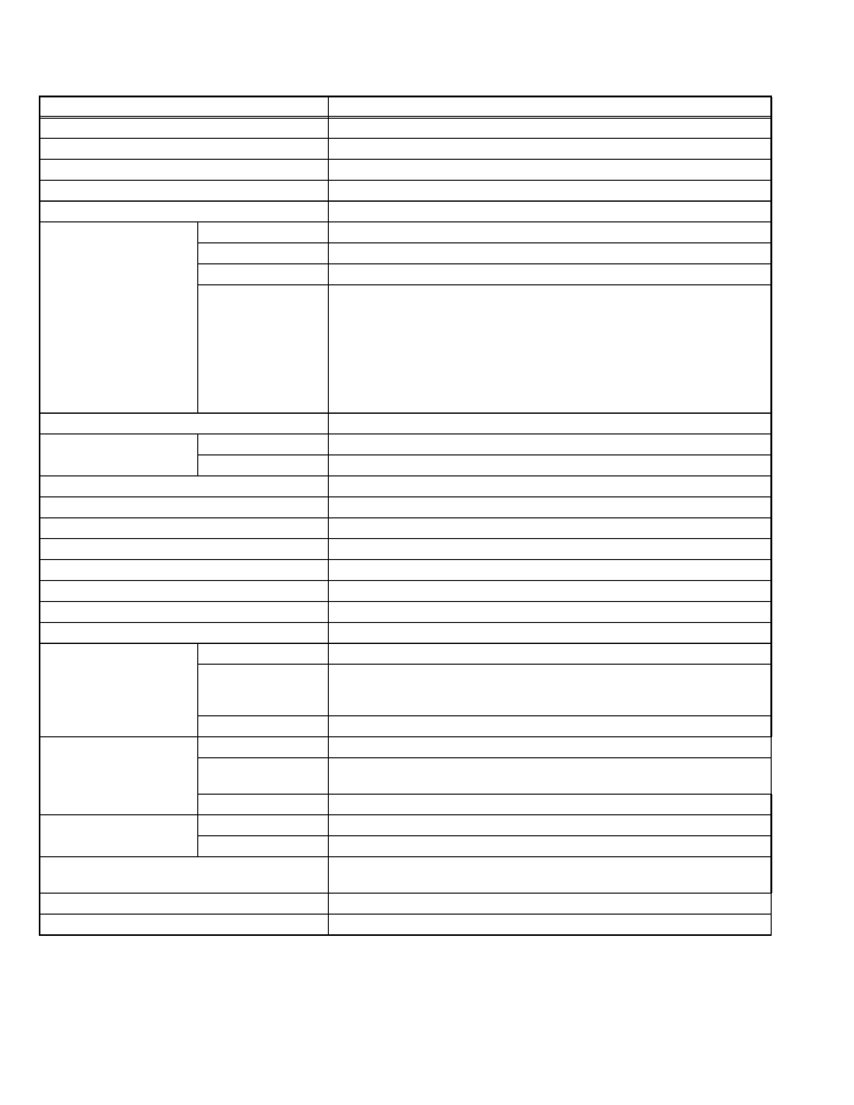
SPECIFICATION
Design & specifications are subject to change without notice.
Items
Contents
Dimensions (W
× H × D)
75.8 cm
× 59.3 cm × 50.0cm (29-7/8" × 23-3/8" × 19-3/4")
Mass
43.0kg (94.6Ibs)
TV RF System
CCIR(M)
Color System
NTSC
Sound System
BTSC (Multi Channel Sound)
TV Receiving Channels
and Frequency
VHF LOW 02ch~06ch : 54MHz~88MHz
VHF HIGH 07ch~13ch : 174MHz~216MHz
UHF 14ch~69ch : 470MHz~806MHz
CATV 54MHz~804MHz
Low Band : 02~06, A-8 by 02~06&01
High Band : 07~13 by 07~13
Mid Band : A~I by 14~22
Super Band : J~W by 23~36
Hyper Band : W+1~W+28 by 37~64
Ultra Band : W+29~W+84 by 65~125
Sub Mid Band : A8, A4~A1 by 01, 96~99
TV / CATV Total Channel
180 Channels
Intermediate Frequency
Video IF Carrier 45.75 MHz
Sound IF Carrier 41.25 MHz (4.5MHz)
Color Sub Carrier
3.58 MHz
Power Input
AC120V , 60Hz
Power Consumption
128W
Picture Tube (Visible size)
68cm (27") Measured diagonally (H : 54.4cm
× W : 41.8cm)
High Voltage
30.0kV ±1.3kV
Speaker
5cm
× 12cm (2" × 4-3/4"), Oval type × 2
Audio Power Output
5W + 5W
Antenna Terminal (VHF / UHF)
F-type connector, 75
unbalanced
Input1 (Rear)
Video 1V(p-p), negative sync, 75
, RCA pin jack × 1
S-video Mini DIN 4-pin
× 1
Y : 1V(p-p), negative sync, 75
C : 0.286V(p-p)(burst signal), 75
Audio 500mV(rms)(-4dBs), high impedance, RCA pin jack
× 2
Input2 (Rear)
Video 1V(p-p), negative sync, 75
, RCA pin jack × 1
Component Video Y : 1V(p-p), negative sync, 75
, RCA pin jack × 1
Pb/Pr : 0.7V(p-p), 75
, RCA pin jack × 2
Audio 500mV(rms)(-4dBs), high impedance, RCA pin jack
× 2
Input3 (Front)
Video 1V(p-p), negative sync, 75
, RCA pin jack × 1
Audio 500mV(rms)(-4dBs), high impedance, RCA pin jack
× 2
Audio Output (Fix)
500mV(rms)(-4dBs), low Impedance, (400kHz when modulated 100%),
RCA pin jack
× 2
AV COMPULINK lll
3.5mm mini jack
× 1
Remote Control Unit
RM-C1252G (AA/R6/UM-3 battery
× 2)
(No.52155)1-3
SECTION 1
PRECAUTION
1.1
SAFETY PRECAUTIONS
(1) The design of this product contains special hardware, many
circuits and components specially for safety purposes. For
continued protection, no changes should be made to the original
design unless authorized in writing by the manufacturer.
Replacement parts must be identical to those used in the original
circuits. Service should be performed by qualified personnel only.
(2) Alterations of the design or circuitry of the products should not be
made. Any design alterations or additions will void the
manufacturer's warranty and will further relieve the manufacturer
of responsibility for personal injury or property damage resulting
therefrom.
(3) Many electrical and mechanical parts in the products have special
safety-related characteristics. These characteristics are often not
evident from visual inspection nor can the protection afforded by them
necessarily be obtained by using replacement components rated for
higher voltage, wattage, etc. Replacement parts which have these
special safety characteristics are identified in the parts list of Service
manual. Electrical components having such features are
identified by shading on the schematics and by (
) on the
parts list in Service manual. The use of a substitute replacement
which does not have the same safety characteristics as the
recommended replacement part shown in the parts list of Service
manual may cause shock, fire, or other hazards.
(4) Use isolation transformer when hot chassis.
The chassis and any sub-chassis contained in some products are
connected to one side of the AC power line. An isolation
transformer of adequate capacity should be inserted between the
product and the AC power supply point while performing any
service on some products when the HOT chassis is exposed.
(5) Don't short between the LIVE side ground and ISOLATED (NEU-
TRAL) side ground or EARTH side ground when repairing.
Some model's power circuit is partly different in the GND. The differ-
ence of the GND is shown by the LIVE : (
) side GND, the ISOLAT-
ED (NEUTRAL) : (
) side GND and EARTH : (
) side GND.
Don't short between the LIVE side GND and ISOLATED (NEUTRAL)
side GND or EARTH side GND and never measure the LIVE side
GND and ISOLATED (NEUTRAL) side GND or EARTH side GND at
the same time with a measuring apparatus (oscilloscope etc.). If
above note will not be kept, a fuse or any parts will be broken.
(6) If any repair has been made to the chassis, it is recommended that
the B1 setting should be checked or adjusted (See B1 POWER
SUPPLY check).
(7) The high voltage applied to the picture tube must conform with that
specified in Service manual. Excessive high voltage can cause an
increase in X-Ray emission, arcing and possible component
damage, therefore operation under excessive high voltage
conditions should be kept to a minimum, or should be prevented.
If severe arcing occurs, remove the AC power immediately and
determine the cause by visual inspection (incorrect installation,
cracked or melted high voltage harness, poor soldering, etc.). To
maintain the proper minimum level of soft X-Ray emission,
components in the high voltage circuitry including the picture tube
must be the exact replacements or alternatives approved by the
manufacturer of the complete product.
(8) Do not check high voltage by drawing an arc. Use a high voltage
meter or a high voltage probe with a VTVM. Discharge the picture
tube before attempting meter connection, by connecting a clip lead
to the ground frame and connecting the other end of the lead
through a 10k
2W resistor to the anode button.
(9) When service is required, observe the original lead dress. Extra
precaution should be given to assure correct lead dress in the high
voltage circuit area. Where a short circuit has occurred, those
components that indicate evidence of overheating should be
replaced.
Always
use
the
manufacturer's
replacement
components.
(10) Isolation Check (Safety for Electrical Shock Hazard)
After re-assembling the product, always perform an isolation
check on the exposed metal parts of the cabinet (antenna
terminals, video/audio input and output terminals, Control knobs,
metal cabinet, screw heads, earphone jack, control shafts, etc.) to
be sure the product is safe to operate without danger of electrical
shock.
a) Dielectric Strength Test
The isolation between the AC primary circuit and all metal parts
exposed to the user, particularly any exposed metal part having a
return path to the chassis should withstand a voltage of 1100V AC
(r.m.s.) for a period of one second.
(. . . . Withstand a voltage of 1100V AC (r.m.s.) to an appliance rat-
ed up to 120V, and 3000V AC (r.m.s.) to an appliance rated 200V
or more, for a period of one second.) This method of test requires
a test equipment not generally found in the service trade.
b) Leakage Current Check
Plug the AC line cord directly into the AC outlet (do not use a line
isolation transformer during this check.). Using a "Leakage
Current Tester", measure the leakage current from each exposed
metal part of the cabinet, particularly any exposed metal part
having a return path to the chassis, to a known good earth ground
(water pipe, etc.). Any leakage current must not exceed 0.5mA AC
(r.m.s.).
However, in tropical area, this must not exceed 0.2mA AC (r.m.s.).
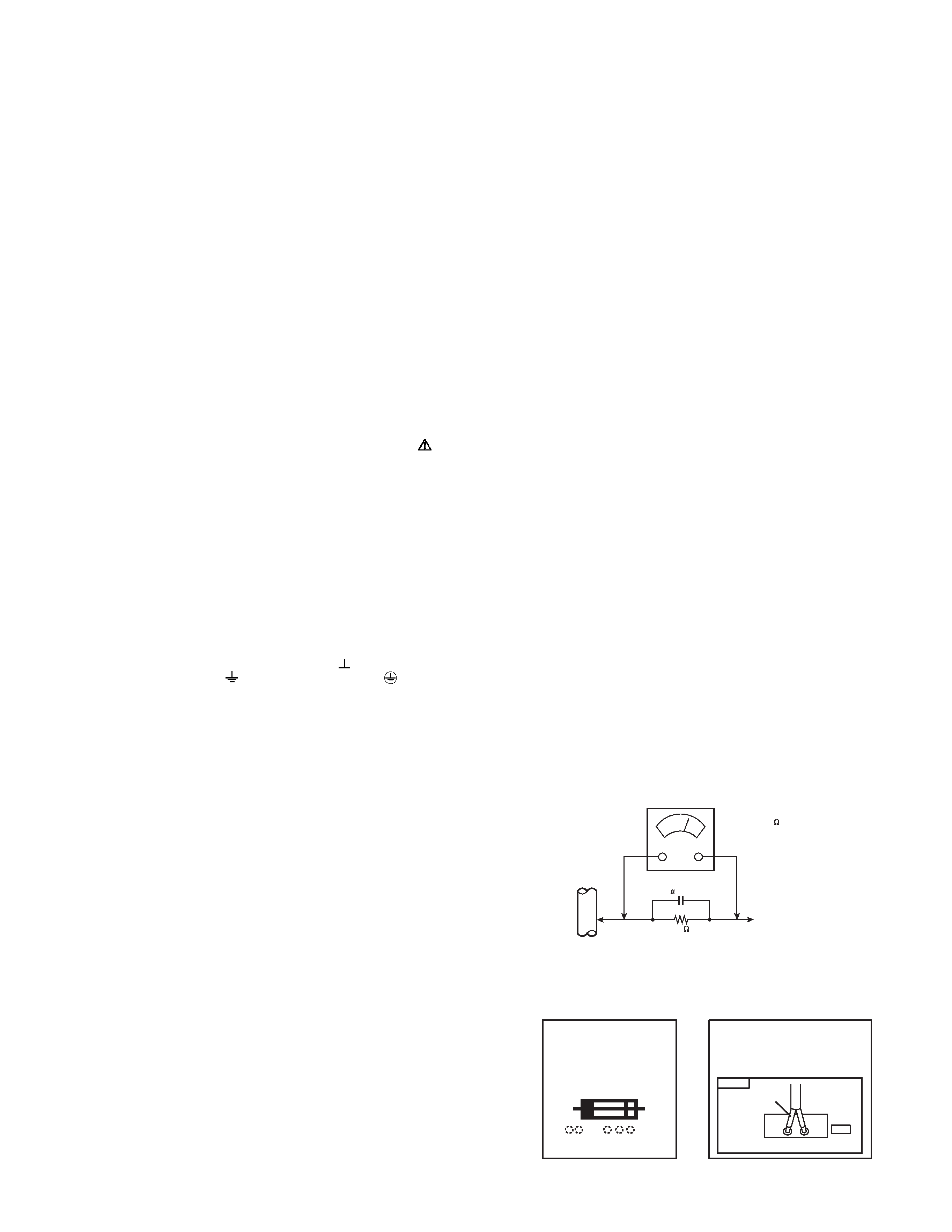
Alternate Check Method
Plug the AC line cord directly into the AC outlet (do not use a
line isolation transformer during this check.). Use an AC
voltmeter having 1000
per volt or more sensitivity in the
following manner. Connect a 1500
10W resistor paralleled by
a 0.15
µF AC-type capacitor between an exposed metal part
and a known good earth ground (water pipe, etc.). Measure the
AC voltage across the resistor with the AC voltmeter. Move the
resistor connection to each exposed metal part, particularly any
exposed metal part having a return path to the chassis, and
measure the AC voltage across the resistor. Now, reverse the
plug in the AC outlet and repeat each measurement. Any
voltage measured must not exceed 0.75V AC (r.m.s.). This
corresponds to 0.5mA AC (r.m.s.).
However, in tropical area, this must not exceed 0.3V AC
(r.m.s.). This corresponds to 0.2mA AC (r.m.s.).
(11) High voltage hold down circuit check.
After repair of the high voltage hold down circuit, this circuit shall
be checked to operate correctly.See item "How to check the high
voltage hold down circuit".
AC VOLTMETER
(HAVING 1000 /V,
OR MORE SENSITIVITY)
PLACE THIS PROBE
ON EACH EXPOSED
METAL PART
1500
10W
0.15 F AC-TYPE
GOOD EARTH GROUND
PWB
White line side
WHT
PW
POWER CORD
REPLACEMENT WARNING.
Connecting the white line side of power
cord to "WHT" character side.
A
V
This mark shows a fast
operating fuse, the
letters indicated below
show the rating.
1-4 (No.52155)
SECTION 2
SPECIFIC SERVICE INSTRUCTIONS
2.1
FEATURES
· New chassis (GJ2) design enables use of a single board with
simplified circuitry.
· Users can make fun to connect the DVD player with the
component video signal input terminal.
· Provided with miniature tuner (TV/CATV).
· Multifunctional remote control permits picture adjustment.
· Adoption of the CHANNEL GUARD function prevents the
specific channels from being selected, unless the "ID number"
is key in.
·I2C bus control utilizes single chip ICs.
· Adoption of the VIDEO STATUS / THEATER PRO. function.
· Adoption of the ON/OFF TIMER and SLEEP TIMER function.
· Built-in V-CHIP system.
· Closed-caption broadcasts can be viewed.
· HYPER-SURROUND system.
· S-VIDEO input terminal for taking best advantage of Super
VHS.
· Digital Comb filter Improved picture quality.
· Adoption of the ASPECT MODE (4:3/ 16:9) function.
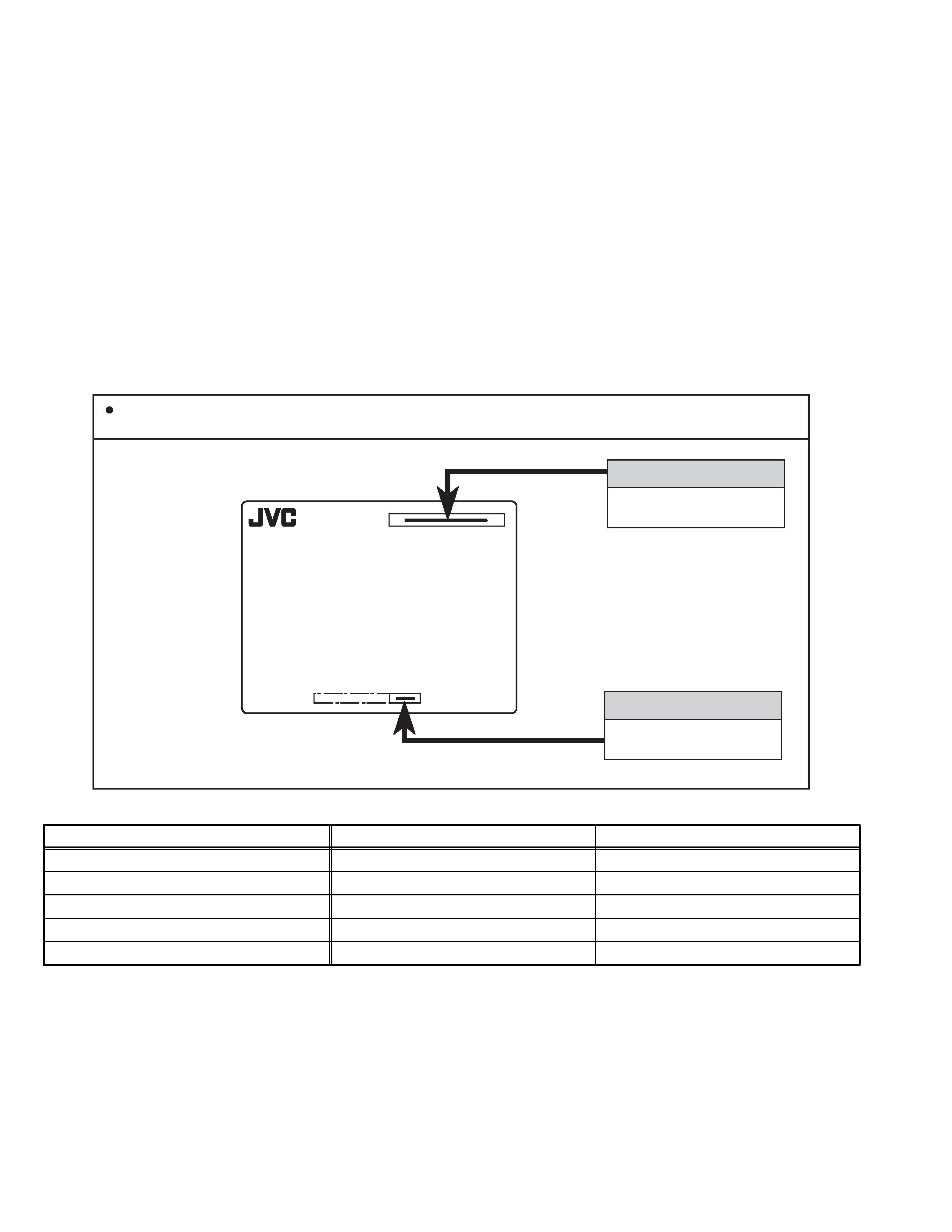
2.2
HOW TO IDENTIFY MODELS
2.3
MAIN DIFFERENCE LIST
AV-N29704
ASA or AZA
DISTINGUISH NAME
MODEL NAME
MODEL NO.
SERIAL NO.
How to recognize from the appearance of the model concerned is written below. Please distinguish from several contents
currently printed on the rating label.
Item
AV-N29704/ASA
AV-N29704/AZA
MAIN PWB ASSY
SGJ-1521A-M2
SGJ-1522A-M2
CRT SOCKET PWB ASSY
SGJ-3002A-M2
SGJ-3006A-M2
AV SELECTOR PWB ASSY
SGJ-5501A-M2
FRONT CONTROL PWB ASSY
SGJ-6001A-M2
PICTURE TUBE (ITC)
A68QCP893X002
A68QCU754X62Q
(No.52155)1-5
2.4
TECHNINAL INFORMATION
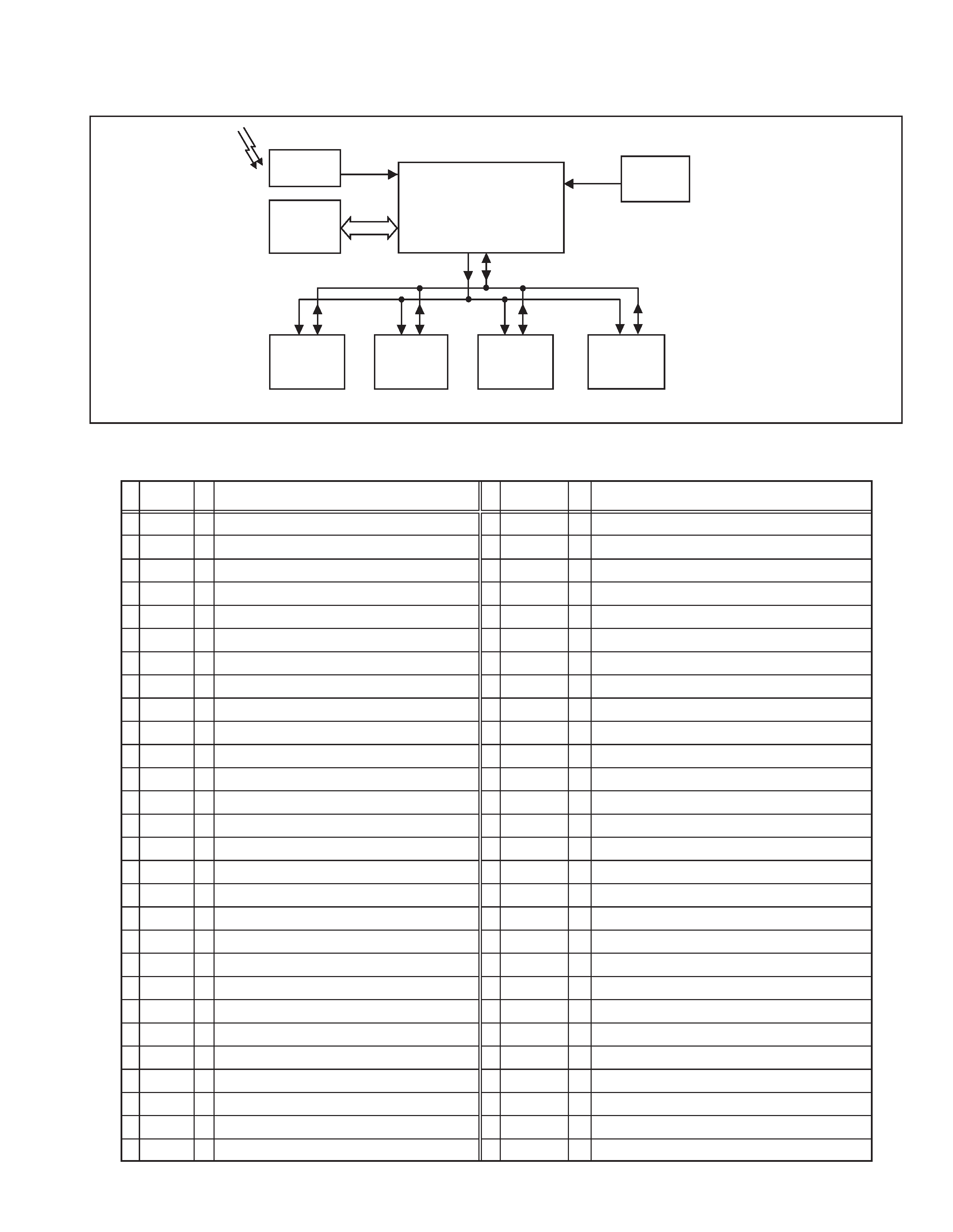
2.4.1 SYSTEM BLOCK DIAGRAM
2.4.2 MAIN MI-COM (CPU) PIN FUNCTION
SCL1
SDA1
AFT1
SCL0
SDA0
SCL0
SDA0
SCL0
SDA0
MAIN MI-COM /
VIDEO PROCESS /
DEF. PROCESS
IC101
IF DET
TU001
TUNER
IC5501
SCL0
SDA0
IC5001
MTS
TONE/VOL
SCL0
SDA0
IC5201
3-LINE YC SEP.
LATCH&
AV SW
IC201
REMOCON
REMOCON
RECEIVER
IC702
MEMORY
Function
Pin
No.
29
30
31
32
33
34
35
36
37
38
39
40
41
42
43
44
45
46
47
48
49
50
51
52
53
54
55
56
Pin name
YCD_GND
Vin1
ABCL
Monitor
Black_Det
SVM_out
APL_Fil
APC_Fil
3.58MHz
YC_Vcc_5V
R_out
G_out
B_out
RGB_Vcc_9V
IK in
TV_DGND
uP_MPAGND
uP_MPAVDD
MAIN_POWER
HAZARD
SDAO
SCLO
SDA1
AGC ADJUST
SCL1
LED
REMOCON
COMPULINK
GND
Not used
Current for automatic beam (brightness)/contrast limit
Not used
Black level detection filter
Y signal for scan velocity modulation
Average picture level filter
Automatc phase control filter
Color sub carrier (3.58MHz) for 3-line digital comb filter [IC5201]
5V (for video process circuit)
R signal
G signal
B signal
9V (for RGB process circuit)
Not used
GND
GND
5V
Power on/off switching control [Powen on : L]
B1 over cuurent / V. amplitude detection (for protect) [Defective : H]
Data for Inter IC control bus (for various devices)
Clock for Inter IC control bus (for various devices)
Data for Inter IC control bus (for main memory)
AGC adjustment (for tuner) <S45 in Service menu>
Clock for Inter IC control bus (for main memory)
POWER / ON TIMER LED lndication [lighting : L]
Remote control sensor input [No input : H]
AV COMPULINK lll control [No input : H]
Function
Pin
No.
1
2
3
4
5
6
7
8
9
10
11
12
13
14
15
16
17
18
19
20
21
22
23
24
25
26
27
28
Pin name
AFT2
AFT1
KEY
uP DVss
Reset
Xout
Xin
TEST
uP_DVDD
AGC_MUTE
UP_VVss
TV_HGND
FBP_SCP
Hout
H_Vcc_9V
HAFC_1
Vsaw
Vout
EW_out
Xray
Ys
Cb_input
Y_input
Cr_input
DVcc_3.3V
V3in/Cin
EHT_in
V2in/Y
Not used
AFT voltage for tuner (Tuning frequency control)
Key scan for front control [No signal : H]
GND
CPU reset
CPU system clock : 8MHz oscillation
CPU system clock : 8MHz oscillation
GND
5V
AGC muting for tuner (when channel select) [Muting : H]
GND
GND
Flyback pulse (H. pulse)
H. drive (oscillation)
9V (for H. oscillation start)
H. AFC filter
V. saw filter
V. drive
Parabola waveform (for sidepin correection)
X-ray detection (for protection) [Detection : H]
Not used
Cb (external) signal
Y (external) signal
Cr (external) signal
3.3V
Chroma signal (for YC separation output)
Not used
Y signal (for YC separation output)
I/O
I
I
I
-
I
O
I
-
-
O
-
-
I
O
-
-
-
O
O
I
I
I
I
I
-
I
I
I
I/O
-
I
I
O
-
O
-
-
O
-
O
O
O
-
I
-
-
-
O
I
I/O
O
I/O
O
O
O
I
I