SERVICE MANUAL
AV-N29702
AV-N29702/AS
COLOR TELEVISION
BASIC CHASSIS
AC
No. 51885B
Jan. 2002
COPYRIGHT © 2002 VICTOR COMPANY OF JAPAN, LTD.
Supplementary
The following items for the AV-N29702/AS model were changed from those of the AV-
N29702/S model.
Therefore, this service manual describes only the items which differ from those of the
AV-N29702/S service manual.
For details other than those described in this manual, please refer the AV-N29702/S serv-
ice manual (No. 51885, Jan., 2002).
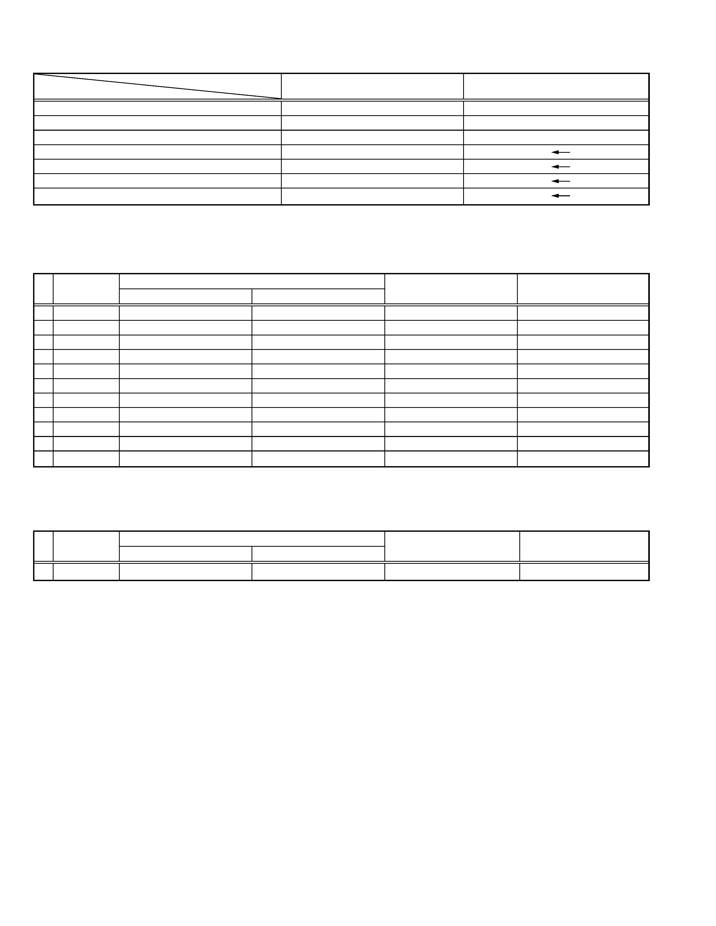
Model No. & Parts No.
!
Ref.No.
AV-N29702/S
AV-N29702/AS
Parts Name
Remarks
(No. 51885)
(No. 51885B)
EXPLODED VIEW PARTS LIST (Page 30)
! V01
A68QCP891X002
A68QCP893X002
PICTURE TUBE
Not Interchangeable
4
LC20217-004A-A
LC20217-004B-A
CONTROL KNOB
----
LC31238-001A-A
OPERATION SHEET
DIFFERENCE PARTS LIST
Model No. & Parts No.
!
Ref.No.
AV-N29702/S
AV-N29702/AS
Parts Name
Remarks
(No. 51885)
(No. 51885B)
PACKING PARTS LIST (Page 39)
! 6
LCT1019-001A-A
LCT1019-001B-A
INST BOOK
Not Interchangeable
AV-N29702
2
No. 51885B
USING P. W. BOARD (Page 30)
PWB No. & Parts No.
! Symbol. No.
SAC-1543A-M2
SAC-1546A-M2
Parts Name
Remarks
MAIN PWB ASS'Y PARTS LIST (Page 32 35)
R1440
NRSA63J-101X
--
MG R
R1441
NRSA63J-103X
--
MG R
! R1535
NRSA02D-242X
NRSA02D-392X
MF R
3.9kØ
1/10W ±0.5%
R1536
--
NRSA02D-823X
MF R
82kØ
1/10W ±0.5%
! C1510
QFZ0196-402
QFZ0196-532
MPP CAP.
5300pF 1.5kVH
±3%
C1999
QRE141J-0R0Y
BW
C R
! T1502
QQH0084-001
QQH0119-001
FBT
! L1521
QQLZ018-480
--
HEATER CHOKE
Q1440
2SC2412K/QR/-X
--
SI.TRANSISTOR
IC1701
MN1876478JL
MN1876478JL1
I.C (MICRO-COMPO)
! FR1526
--
QRZ9013-R27
F R
0.27Ø
1/2W
K
MODEL
AV-N29702/S
AV-N29702/AS
PWB ASS'Y
(No. 51885)
(No. 51885B)
MAIN PWB
SAC-1543A-M2
SAC-1546A-M2
DAF PWB
SAC-2602A-M2
--
CRT SOCKET PWB
SAC-3502A-M2
SAC-3515A-M2
FRONT PWB
SAC-8503A-M2
POWER SW PWB
SAC-8601A-M2
LF PWB
SAC-9501A-M2
AV SW PWB
SAC0S502A-M2
PWB No. & Parts No.
! Symbol. No.
SAC-3502A-M2
SAC-3515A-M2
Parts Name
Remarks
CRT SOCKET PWB ASS'Y PARTS LIST (Page 36)
! SK3001
CE42670-001
QNZ0464-001
C.R.T.SOCKET
AV-N29702
No. 51885B
3
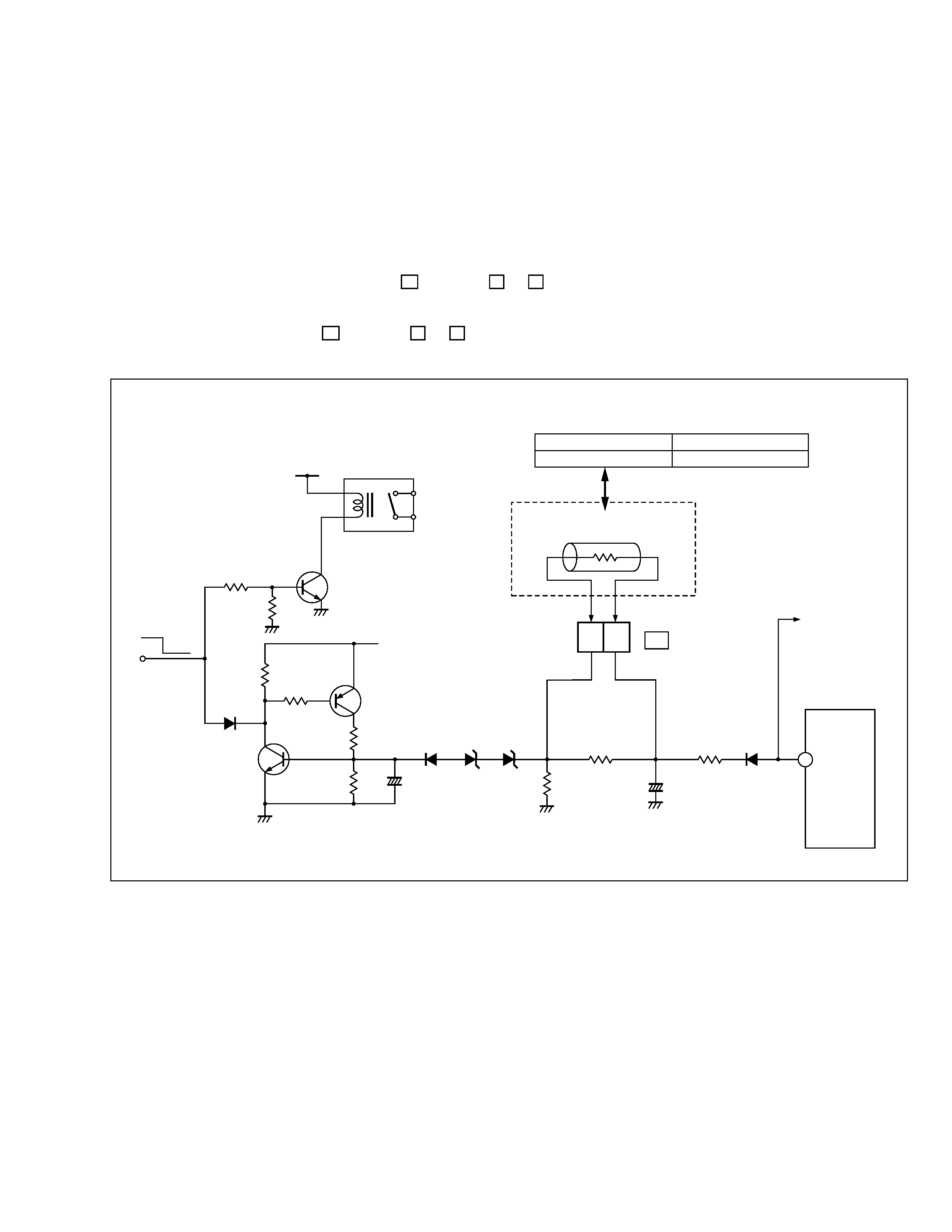
SERVICE ADJUSTMENT
HOW TO CHECK THE HIGH VOLTAGE HOLD DOWN CIRCUIT (Page 27)
1. HIGH VOLTAGE HOLD DOWN CIRCUIT
After repairing the high voltage hold down circuit shown in Fig. 1.
This circuit shall be checked to operate correctly.
2. CHECKING OF THE HIGH VOLTAGE HOLD DOWN CIRCUIT
(1) Turn the POWER SW ON.
(2) As shown in Fig. 1, set the resistor (between S1 connector
2
&
3
).
(3) Make sure that the screen picture disappears.
(4) Temporarily unplug the power cord.
(5) Remove the resistor (between S1 connector
2
&
3
).
(6) Again plug the power cord, make sure that the normal picture is displayed on the screen.
Fig. 1
23
S1
CONNECTOR
HEATER
+
+
POWER
ON OFF
RY951
R952
D535
R532
R951
Q951
Q532
Q531
R533
R534
R535
R538
C533
D534
D531
D532
BW
C525
R537
FR525
D525
T502
4
RESISTOR
AV-N29702/S
20.3 kØ
± 101 Ø 1/4 W
AV-N29702/AS
15.0 kØ
± 75 Ø 1/4 W

Printed in Japan
VP0201
SW
N29702AS-MEM #4
JVC SERVICE & ENGINEERING COMPANY OF AMERICA
Head office :
1700 Valley Road, Wayne, New Jersey 07470
(973)317-5000
East Coast :
10 New Maple Avenue, Pine Brook, New Jersey 07058
(973)396-1000
Midwest
:
705 Enterprise St. Aurora, Illinois 60504
(630)851-7855
West Coast :
5665 Corporate Avenue, Cypress, California 90630
(714)229-8011
Southwest :
10700 Hammerly, Suite 105, Houston, Texas 77043
(713)935-9331
Hawaii
:
2969 Mapunapuna Place, Honolulu, Hawaii 96819
(808)833-5828
Southeast :
1500 Lakes Parkway, Lawrenceville, Georgia 30243
(770)339-2582
JVC CANADA INC.
Head office :
21 Finchdene Square Scarborough, Ontario M1X 1A7
(416)293-1311
Vancouver :
13040 Worster Court Richmond B.C. V6V 2B3
(604)270-1311
DIVISION OF JVC AMERICAS CORP.
SERVICE MANUAL
AV-N29702
AV-N29702/S
COLOR TELEVISION
BASIC CHASSIS
AC
No. 51885
Dec. 2001
COPYRIGHT © 2001 VICTOR COMPANY OF JAPAN, LTD.
TV
CONTENTS
a SPECIFICATIONS ....................................................................................................................................2
a SAFETY PRECAUTIONS ........................................................................................................................3
a FEATURES ..............................................................................................................................................4
a FUNCTIONS .............................................................................................................................................5
a SPECIFIC SERVICE INSTRUCTIONS ....................................................................................................6
a SERVICE ADJUSTMENTS ....................................................................................................................11
¤ STANDARD CIRCUIT DIAGRAM (APPENDIX) .................................................................................. 2-1
a PARTS LIST ...........................................................................................................................................29