AV-36230 /AH AV-36260 /AH
AV-36230 /AR AV-36260 /AR
SERVICE MANUAL
AV-36230
AV-36260
COLOR TELEVISION
BASIC CHASSIS
GC
No. 51801B
Oct. 2001
COPYRIGHT © 2001 VICTOR COMPANY OF JAPAN, LTD.
TV
TV
RM-C305
[AV-36260]
RM-C306
[AV-36230]
CONTENTS
a SAFETY PRECAUTIONS
AV-36230 /AM AV-36260 /AM
¤ STANDARD CIRCUIT DIAGRAM (APPENDED)
a SERVICE ADJUSTMENTS
¤ OPERATING INSTRUCTIONS (APPENDED)
PRELIMINARY
No. 51801B
2
AV-36230
AV-36260
SAFETY PRECAUTIONS
1. The design of this product contains special hardware, many circuits
and components specially for safety purposes. For continued pro-
tection, no changes should be made to the original design unless
authorized in writing by the manufacturer. Replacement parts must
be identical to those used in the original circuits. Service should be
performed by qualified personnel only.
2. Alterations of the design or circuitry of the products should not be
made. Any design alterations or additions will void the manufactur-
er's warranty and will further relieve the manufacturer of responsi-
bility for personal injury or property damage resulting therefrom.
3. Many electrical and mechanical parts in the products have special
safety-related characteristics. These characteristics are often not
evident from visual inspection nor can the protection afforded by
them necessarily be obtained by using replacement components
rated for higher voltage, wattage, etc. Replacement parts which have
these special safety characteristics are identified in the parts list of
Service manual. Electrical components having such features are
identified by shading on the schematics and by (
) on the
parts list in Service manual. The use of a substitute replacement
which does not have the same safety characteristics as the recom-
mended replacement part shown in the parts list of Service manual
may cause shock, fire, or other hazards.
4. Use isolation transformer when hot chassis.
The chassis and any sub-chassis contained in some products are
connected to one side of the AC power line. An isolation transformer
of adequate capacity should be inserted between the product and
the AC power supply point while performing any service on some
products when the HOT chassis is exposed.
5. Don't short between the LIVE side ground and ISOLATED (NEU-
TRAL) side ground or EARTH side ground when repairing.
Some model's power circuit is partly different in the GND. The dif-
ference of the GND is shown by the LIVE : (
) side GND, the
ISOLATED(NEUTRAL) : (
) side GND and EARTH : (
) side
GND. Don't short between the LIVE side GND and
ISOLATED(NEUTRAL) side GND or EARTH side GND and never
measure with a measuring apparatus (oscilloscope etc.) the LIVE
side GND and ISOLATED(NEUTRAL) side GND or EARTH side
GND at the same time.
If above note will not be kept, a fuse or any parts will be broken.
6. If any repair has been made to the chassis, it is recommended that
the B1 setting should be checked or adjusted (See ADJUSTMENT
OF B1 POWER SUPPLY).
7. The high voltage applied to the picture tube must conform with that
specified in Service manual. Excessive high voltage can cause an
increase in X-Ray emission, arcing and possible component dam-
age, therefore operation under excessive high voltage conditions
should be kept to a minimum, or should be prevented. If severe
arcing occurs, remove the AC power immediately and determine
the cause by visual inspection (incorrect installation, cracked or
melted high voltage harness, poor soldering, etc.). To maintain the
proper minimum level of soft X-Ray emission, components in the
high voltage circuitry including the picture tube must be the exact
replacements or alternatives approved by the manufacturer of the
complete product.
8. Do not check high voltage by drawing an arc. Use a high voltage
meter or a high voltage probe with a VTVM. Discharge the picture
tube before attempting meter connection, by connecting a clip lead
to the ground frame and connecting the other end of the lead through
a 10kØ 2W resistor to the anode button.
9. When service is required, observe the original lead dress. Extra
precaution should be given to assure correct lead dress in the high
voltage circuit area. Where a short circuit has occurred, those com-
ponents that indicate evidence of overheating should be replaced.
Always use the manufacturer's replacement components.
10. Isolation Check
(Safety for Electrical Shock Hazard)
After re-assembling the product, always perform an isolation check
on the exposed metal parts of the cabinet (antenna terminals, video/
audio input and output terminals, Control knobs, metal cabinet,
screwheads, earphone jack, control shafts, etc.) to be sure the prod-
uct is safe to operate without danger of electrical shock.
(1) Dielectric Strength Test
The isolation between the AC primary circuit and all metal parts
exposed to the user, particularly any exposed metal part having a
return path to the chassis should withstand a voltage of 1100V AC
(r.m.s.) for a period of one second.
(. . . . Withstand a voltage of 1100V AC (r.m.s.) to an appliance rated
up to 120V, and 3000V AC (r.m.s.) to an appliance rated 200V or
more, for a period of one second.)
This method of test requires a test equipment not generally found in
the service trade.
(2) Leakage Current Check
Plug the AC line cord directly into the AC outlet (do not use a line
isolation transformer during this check.). Using a "Leakage Current
Tester", measure the leakage current from each exposed metal part
of the cabinet, particularly any exposed metal part having a return
path to the chassis, to a known good earth ground (water pipe, etc.).
Any leakage current must not exceed 0.5mA AC (r.m.s.).
However, in tropical area, this must not exceed 0.2mA AC (r.m.s.).
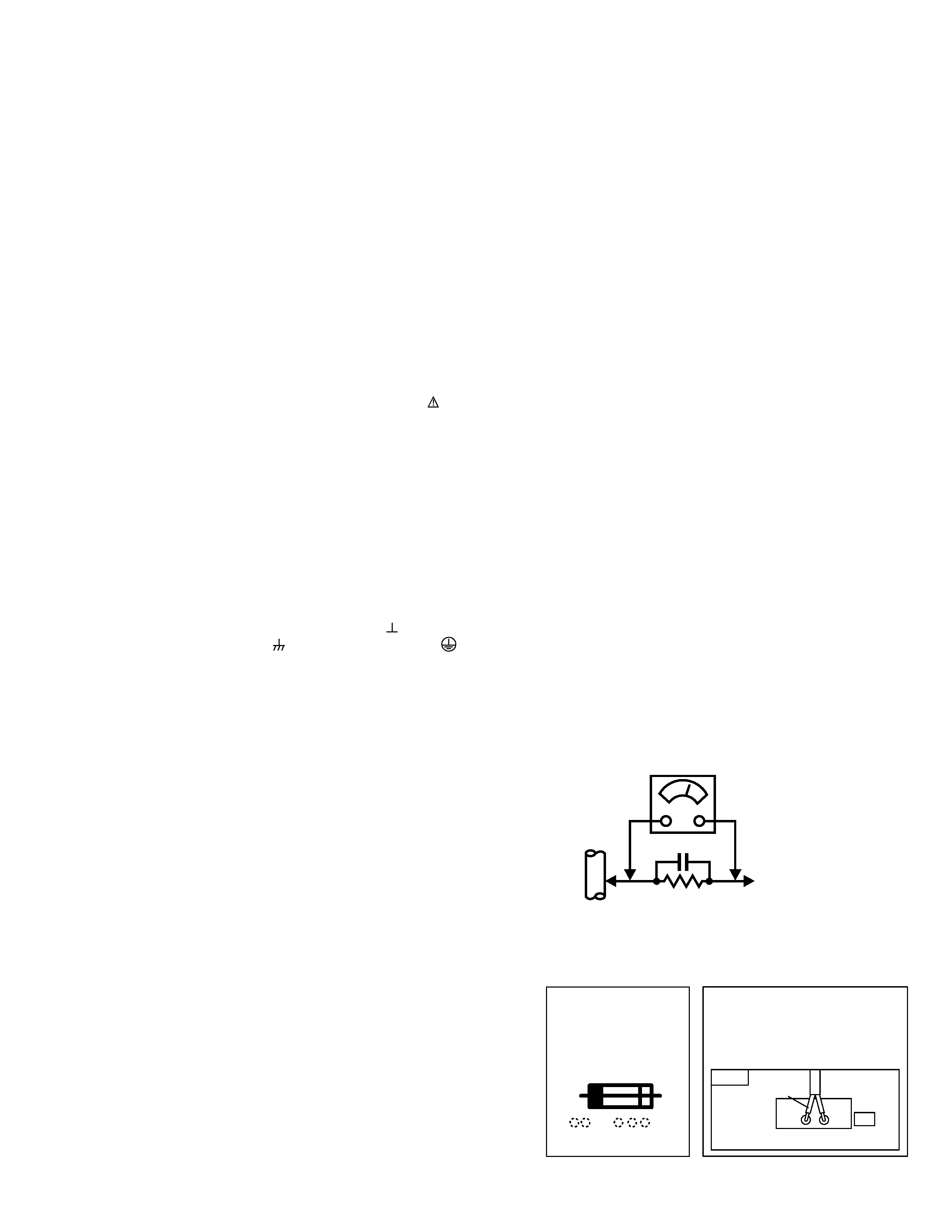
· Alternate Check Method
Plug the AC line cord directly into the AC outlet (do not use a line
isolation transformer during this check.). Use an AC voltmeter hav-
ing 1000 ohms per volt or more sensitivity in the following manner.
Connect a 1500Ø 10W resistor paralleled by a 0.15µF AC-type ca-
pacitor between an exposed metal part and a known good earth
ground (water pipe, etc.). Measure the AC voltage across the resis-
tor with the AC voltmeter. Move the resistor connection to each ex-
posed metal part, particularly any exposed metal part having a re-
turn path to the chassis, and measure the AC voltage across the
resistor. Now, reverse the plug in the AC outlet and repeat each
measurement. Any voltage measured must not exceed 0.75V AC
(r.m.s.). This corresponds to 0.5mA AC (r.m.s.).
However, in tropical area, this must not exceed 0.3V AC (r.m.s.).
This corresponds to 0.2mA AC (r.m.s.).
11. High voltage hold down circuit check.
After repair of the high voltage hold down circuit, this circuit shall be
checked to operate correctly.
See item "How to check the high voltage hold down circuit".
GOOD
EARTH
GROUND
0.15
µF AC-TYPE
AC VOLTMETER
(HAVING 1000Ø/V,
OR MORE SENSITIVITY)
PLACE THIS PROBE
ON EACH EXPOSED
METAL PART
1500Ø 10W
A
V
This mark shows a fast
POWER CORD
REPLACEMENT WARNING
Connecting thr white line side of
power cord to "WHT" character side.
operating fuse, the
letters indicated below
show the rating.
PWB
WHT
PW
White line side
No. 51801B
AV-36230
AV-36260
3
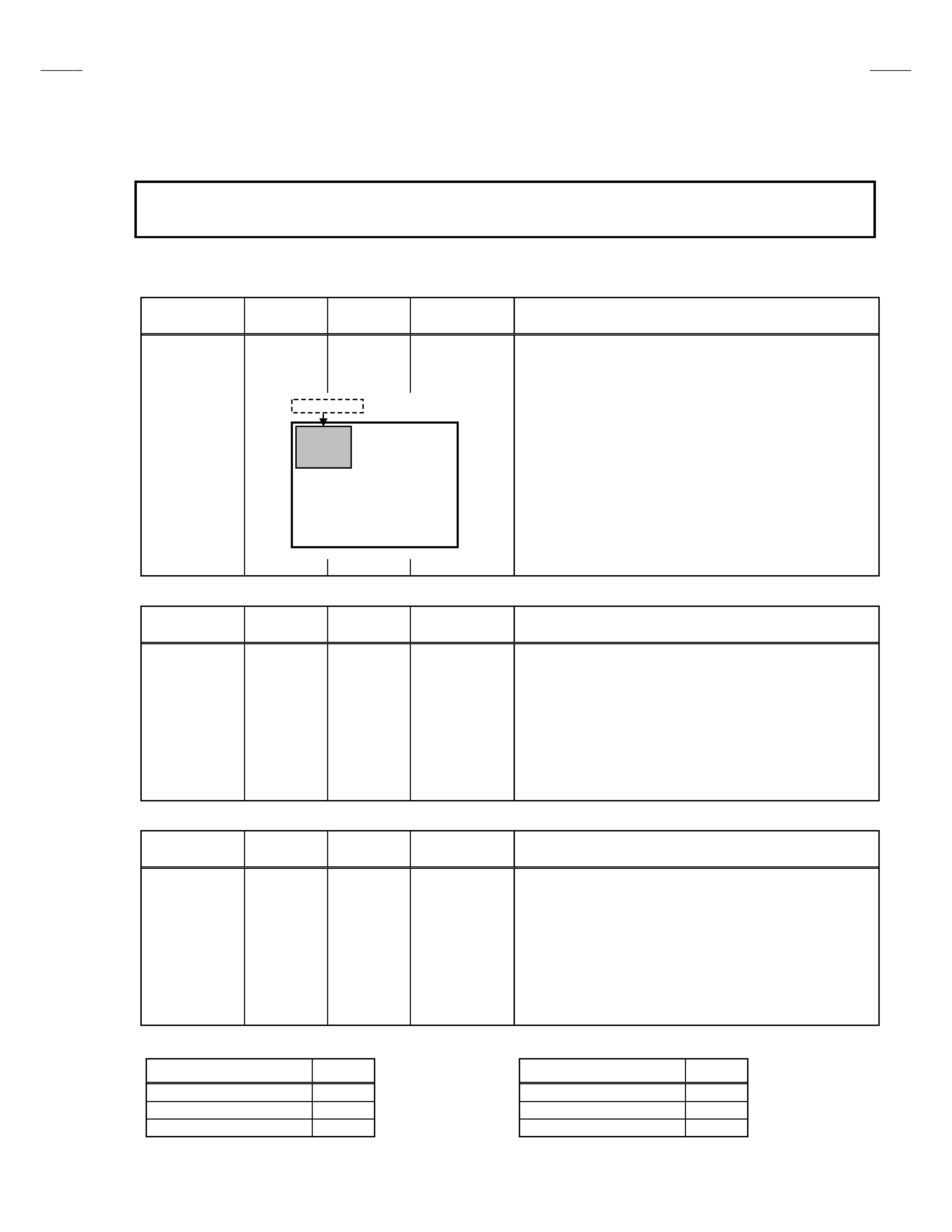
SERVICE ADJUSTMENTS
ADJUSTMENT STEP
PIP VCO [ADDITION : AV-36260 only]
Item
Measuring
instrument
Test point
Adjustment part
Description
PIP VCO
adjustment
PIP VCO transf.
(T111)
[PIP]
1. Set the PIP mode.
2. Receive the ordinary broadcast signal.
3. Select "TU2 VCO" of the SERVICE MENU.
4. Confirm [SYNC] to "YES".
5. Turn the PIP VCO transformer to where "REFERENCE LEVEL"
characters are yellow.
When finished, confirm [SYNC] to "YES" again.
FOCUS [CHANGE]
Item
Measuring
instrument
Test point
Adjustment part
Description
FOCUS
adjustment
Signal
generator
FOCUS VR
[HVT]
! Set the VIDEO STATUS to "STANDARD".
! When makes difference by FOCUS adjustment, should be
recommending CONVERGENCE and PURITY adjustments.
1. Receive a crosshatch signal.
2. White looking at the screen center, adjust the FOCUS VR so that
be clear and in fine detail.
3. Make sure that the picture is in focus even when the screen gets
darkness.
V POSITION & V SIZE [CHANGE]
Item
Measuring
instrument
Test point
Adjustment part
Description
V POSITION &
V SIZE
adjustment
Signal
generator
V CENTER SW
(S421)
No.71 : V POSI
No.66 : V SIZE
No.78 : TRAPEZ
No.65 : V LIN
1. Receive a crosshatch signal.
2. Set the No.71: V POSI to "0".
3. Adjust the V CENTER SW and No.66: V SIZE to the vertical size
is 92%.
4. Confirm the vertical lines to be straight. If it is not straight, adjust
to be straight at the No.78: TRAPEZ.
5. Confirm upper and lower of the screen. If it is not symmetrical,
adjust to be symmetrical at the No.65: V LIN.
SUB COLOR [CHANGE]
SUB TINT [CHANGE]
Model
A [VW-B]
Model
B [VW-B]
AV-36230/AR, AV-36260/AR
+14V
AV-36230/AR, AV-36260/AR
+18V
AV-36230/AH, AV-36260/AH
+10V
AV-36230/AH, AV-36260/AH
+16V
AV-36230/AM, AV-36260/AM
+9V
AV-36230/AM, AV-36260/AM
+9V
TU2 VCO
HIGH LEVEL
REFERENCE LEVEL
LOW LEVEL
SYNC
:
YES
PIP SCREEN
These models (with A mark) were changed chassis from AV-36230 / AV-36260 (AC chassis).
This content describes only items which differ from those of the base models SERVICE MANUAL.
Please refer to the AV-36230 / AV-36260 SERVICE MANUAL (No.51801 issued Feb. 2001).

Printed in Japan
--
0110
H.K/Y.S/A.N
JVC SERVICE & ENGINEERING COMPANY OF AMERICA
DIVISION OF JVC AMERICAS CORP.
Head office :
1700 Valley Road, Wayne, New Jersey 07470
(973)317-5000
East Coast :
10 New Maple Avenue, Pine Brook, New Jersey 07058
(973)396-1000
Midwest
:
705 Enterprise St. Aurora, Illinois 60504
(630)851-7855
West Coast :
5665 Corporate Avenue, Cypress, California 90630
(714)229-8011
Southwest :
10700 Hammerly, Suite 105, Houston,Texas 77043
(713)935-9331
Hawaii
:
2969 Mapunapuna Place, Honolulu, Hawaii 96819
(808)833-5828
Southeast :
1500 Lakes Parkway, Lawrenceville, Georgia 30243
(770)339-2582
JVC CANADA INC.
Head office :
21 Finchdene Square Scarborough, Ontario M1X 1A7
(416)293-1311
Vancouver :
13040 Worster Court Richmond B.C. V6V 2B3
(604)270-1311
®
AV-32230 /AG AV-32260 /AG
AV-32230 /AH AV-32260 /AH
AV-32230 /AM AV-32260 /AM
AV-32230 /AR AV-32260 /AR
SERVICE MANUAL
AV-32230
AV-32260
COLOR TELEVISION
BASIC CHASSIS
GC
No. 51802C
Dec. 2001
COPYRIGHT © 2001 VICTOR COMPANY OF JAPAN, LTD.
TV
TV
RM-C306
[AV-32230]
RM-C305
[AV-32260]
CONTENTS
a SPECIFICATIONS ....................................................................................................................................2
a SAFETY PRECAUTIONS ........................................................................................................................3
a FEATURES ..............................................................................................................................................4
a MAIN DIFFERENCE LIST ........................................................................................................................5
a HOW TO IDENTIFY MODELS ..................................................................................................................5
a FUNCTIONS .............................................................................................................................................6
a SPECIFIC SERVICE INSTRUCTIONS ....................................................................................................7
a SERVICE ADJUSTMENTS ....................................................................................................................13
¤ STANDARD CIRCUIT DIAGRAM (APPENDIX) .................................................................................. 2-1
a PARTS LIST ...........................................................................................................................................35
MC-Service