SERVICE MANUAL
COPYRIGHT © 2003 VICTOR COMPANY OF JAPAN, LIMITED
No.52125
2003/7
COLOUR TELEVISION
52125
2003
04
AV-32H35SAE
TABLE OF CONTENTS
1
PRECAUTION. . . . . . . . . . . . . . . . . . . . . . . . . . . . . . . . . . . . . . . . . . . . . . . . . . . . . . . . . . . . . . . . . . . . . . . . . 1-3
2
SPECIFIC SERVICE INSTRUCTIONS . . . . . . . . . . . . . . . . . . . . . . . . . . . . . . . . . . . . . . . . . . . . . . . . . . . . . . 1-4
3
DISASSEMBLY . . . . . . . . . . . . . . . . . . . . . . . . . . . . . . . . . . . . . . . . . . . . . . . . . . . . . . . . . . . . . . . . . . . . . . . 1-5
4
ADJUSTMENT . . . . . . . . . . . . . . . . . . . . . . . . . . . . . . . . . . . . . . . . . . . . . . . . . . . . . . . . . . . . . . . . . . . . . . . 1-12
5
TROUBLE SHOOTING . . . . . . . . . . . . . . . . . . . . . . . . . . . . . . . . . . . . . . . . . . . . . . . . . . . . . . . . . . . . . . . . . 1-29
1
2
3
4
5
6
7
8
9
0
P
AV
TV
OK
MENU
P
TV
BASIC CHASSIS
ML
1-2 (No.52125)
SPECIFICATION
Design & specifications are subject to change without notice.
Item
Content
Dimensions ( W x H x D )
94.8cm
× 56.2cm × 54.7cm
Mass
51.8kg
TV RF System
CCIR (B/G, D/K, I , L/L')
Colour System
PAL / SECAM / NTSC (Only in EXT mode)
Stereo System
A2 (B/G, D/K) / NICAM (B/G, I, D/K, L)
Teletext System
FLOF (Fastext)
TOP (German system)
WST(World standard system)
Receiving
Frequency
VHF 47MHz ~ 470MHz
UHF 470MHz ~ 862MHz
French CATV 116MHz ~ 172MHz
220MHz ~ 469MHz
Intermediate
Frequency
VIF Carrier 38.9MHz (B/G, D/K, I , L)
33.95MHz (L')
SIF Carrier 33.4MHz (5.5MHz:B/G)
32.9MHz (6.0MHz:I)
32.4MHz (6.5MHz:L, D/K)
40.45MHz (6.5MHz:L')
Colour Sub
Carrier Frequency
PAL 4.43MHz
SECAM 4.40625MHz / 4.25MHz
NTSC 3.58MHz / 4.43MHz
Power Input
AC220V ~ AC240V, 50Hz
Power Consumption
195W(Max) / 130W(Avg), standby : 2.5W
Aerial Input Terminal
75ohm unbalanced, coaxial
Picture Tube
Visible size : 76cm (Measured diagonally) H : 67.4cm
× V : 38.4cm
High Voltage
31.0kV (+1kV / -1.5kV) (CRT cutoff, FULL mode)
Speaker
13cm
× 6.5cm oval type × 2
Audio Power Output
10W + 10W
EXT-1 / EXT-2 / EXT-3
(Input / Output)
21-pin Euro connector (SCART socket
× 3)
EXT-4 (Input)
Video 1V(p-p), positive, 75
(RCA pin jack × 1)
Audio (L/R) 500mV(rms) (-4dBs), High impedance (RCA pin jack
× 2)
S-Video Mini - DIN 4 pin
× 1
Y : 1V(p-p), positive (negative sync provided), 75
C : 0.3V(p-p) (Burst signal), 75
AUDIO OUT (Variable)
0~1000mV(rms), Low impedance (RCA pin jack
× 2)
Headphone Jack
Stereo mini jack (Ø3.5mm)
× 1
Remote Control Unit
RM-C54H (AAA/R03 dry battery
× 2)
(No.52125)1-3
SECTION 1
PRECAUTION
1.1
SAFETY PRECAUTIONS
(1) The design of this product contains special hardware,
many circuits and components specially for safety
purposes. For continued protection, no changes should be
made to the original design unless authorized in writing by
the manufacturer. Replacement parts must be identical to
those used in the original circuits. Service should be
performed by qualified personnel only.
(2) Alterations of the design or circuitry of the products should
not be made. Any design alterations or additions will void
the manufacturer's warranty and will further relieve the
manufacturer of responsibility for personal injury or
property damage resulting therefrom.
(3) Many electrical and mechanical parts in the products have
special
safety-related
characteristics.
These
characteristics are often not evident from visual inspection
nor can the protection afforded by them necessarily be
obtained by using replacement components rated for
higher voltage, wattage, etc. Replacement parts which
have these special safety characteristics are identified in
the parts list of Service manual. Electrical components
having such features are identified by shading on the
schematics and by (
) on the parts list in Service
manual. The use of a substitute replacement which does
not
have
the
same
safety
characteristics
as
the
recommended replacement part shown in the parts list of
Service manual may cause shock, fire, or other hazards.
(4) Don't short between the LIVE side ground and
ISOLATED (NEUTRAL) side ground or EARTH side
ground when repairing.
Some model's power circuit is partly different in the GND.
The difference of the GND is shown by the LIVE : (
) side
GND, the ISOLATED (NEUTRAL) : (
) side GND and
EARTH : (
) side GND.
Don't short between the LIVE side GND and ISOLATED
(NEUTRAL) side GND or EARTH side GND and never
measure the LIVE side GND and ISOLATED (NEUTRAL)
side GND or EARTH side GND at the same time with a
measuring apparatus (oscilloscope etc.). If above note will
not be kept, a fuse or any parts will be broken.
(5) If any repair has been made to the chassis, it is
recommended that the B1 setting should be checked or
adjusted (See ADJUSTMENT OF B1 POWER SUPPLY).
(6) The high voltage applied to the picture tube must conform
with that specified in Service manual. Excessive high
voltage can cause an increase in X-Ray emission, arcing
and possible component damage, therefore operation
under excessive high voltage conditions should be kept to
a minimum, or should be prevented. If severe arcing
occurs, remove the AC power immediately and determine
the cause by visual inspection (incorrect installation,
cracked or melted high voltage harness, poor soldering,
etc.). To maintain the proper minimum level of soft X-Ray
emission, components in the high voltage circuitry
including the picture tube must be the exact replacements
or alternatives approved by the manufacturer of the
complete product.
(7) Do not check high voltage by drawing an arc. Use a high
voltage meter or a high voltage probe with a VTVM.
Discharge the picture tube before attempting meter
connection, by connecting a clip lead to the ground frame
and connecting the other end of the lead through a 10k
2W resistor to the anode button.
(8) When service is required, observe the original lead dress.
Extra precaution should be given to assure correct lead
dress in the high voltage circuit area. Where a short circuit
has occurred, those components that indicate evidence of
overheating
should
be
replaced.
Always
use
the
manufacturer's replacement components.
(9) Isolation Check (Safety for Electrical Shock Hazard)
After re-assembling the product, always perform an
isolation check on the exposed metal parts of the cabinet
(antenna terminals, video/audio input and output terminals,
Control knobs, metal cabinet, screw heads, earphone jack,
control shafts, etc.) to be sure the product is safe to operate
without danger of electrical shock.
a) Dielectric Strength Test
The isolation between the AC primary circuit and all metal
parts exposed to the user, particularly any exposed metal
part having a return path to the chassis should withstand a
voltage of 3000V AC (r.m.s.) for a period of one second. (.
. . . Withstand a voltage of 1100V AC (r.m.s.) to an
appliance rated up to 120V, and 3000V AC (r.m.s.) to an
appliance rated 200V or more, for a period of one second.)
This method of test requires a test equipment not generally
found in the service trade.
b) Leakage Current Check
Plug the AC line cord directly into the AC outlet (do not use
a line isolation transformer during this check.). Using a
"Leakage Current Tester", measure the leakage current
from each exposed metal part of the cabinet, particularly
any exposed metal part having a return path to the chassis,
to a known good earth ground (water pipe, etc.). Any
leakage current must not exceed 0.5mA AC (r.m.s.).
However, in tropical area, this must not exceed 0.2mA AC
(r.m.s.).
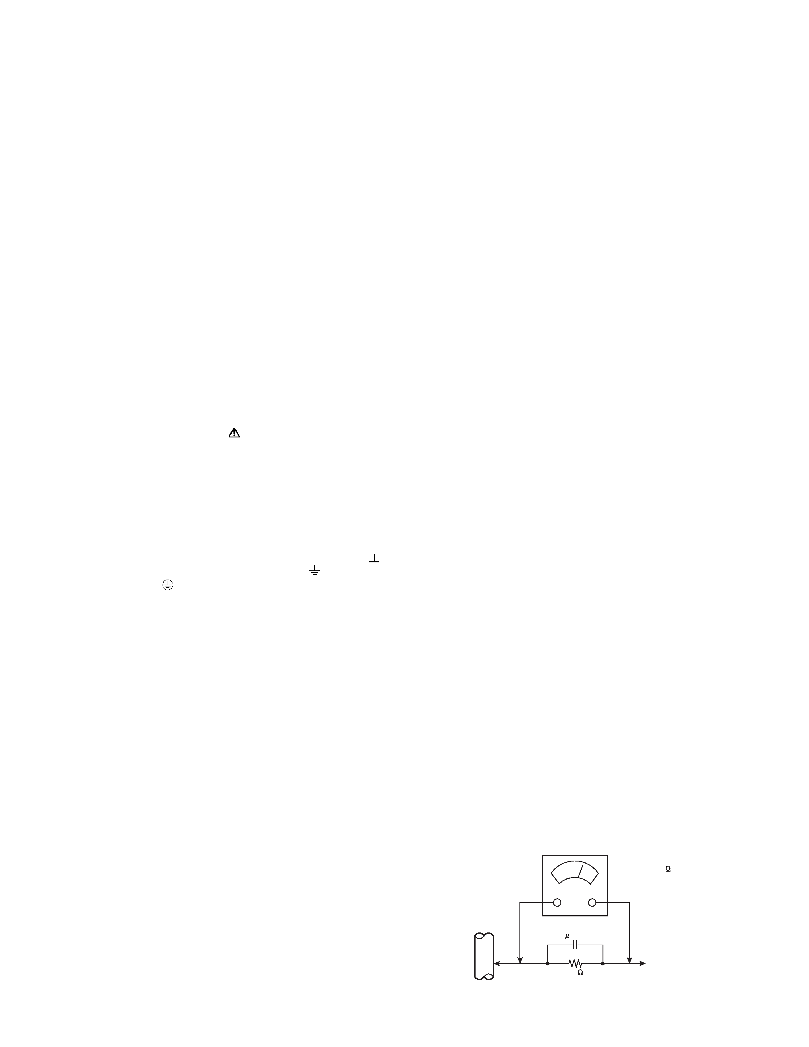
Alternate Check Method
Plug the AC line cord directly into the AC outlet (do not
use a line isolation transformer during this check.). Use
an AC voltmeter having 1000
per volt or more
sensitivity in the following manner. Connect a 1500
10W resistor paralleled by a 0.15
µF AC-type capacitor
between an exposed metal part and a known good earth
ground (water pipe, etc.). Measure the AC voltage
across the resistor with the AC voltmeter. Move the
resistor connection to each exposed metal part,
particularly any exposed metal part having a return path
to the chassis, and measure the AC voltage across the
resistor. Now, reverse the plug in the AC outlet and
repeat each measurement. Any voltage measured must
not exceed 0.75V AC (r.m.s.). This corresponds to
0.5mA AC (r.m.s.).
However, in tropical area, this must not exceed 0.3V AC
(r.m.s.). This corresponds to 0.2mA AC (r.m.s.).
AC VOLTMETER
(HAVING 1000 /V,
OR MORE SENSITIVITY)
PLACE THIS PROBE
ON EACH EXPOSED
METAL PART
1500
10W
0.15 F AC-TYPE
GOOD EARTH GROUND
1-4 (No.52125)
SECTION 2
SPECIFIC SERVICE INSTRUCTIONS
2.1
FEATURES
· New chassis design enable use of an interactive on screen
control.
· The TELETEXT SYSTEM has a built-in FASTEXT (UK
system), TOP (German system) and WST (world standard
system) system.
· Because this TV unit corresponds to multiplex broadcast,
users can enjoy music programs and sporting events with live
realism. In addition, BILINGUAL programs can be heard in
their original language.
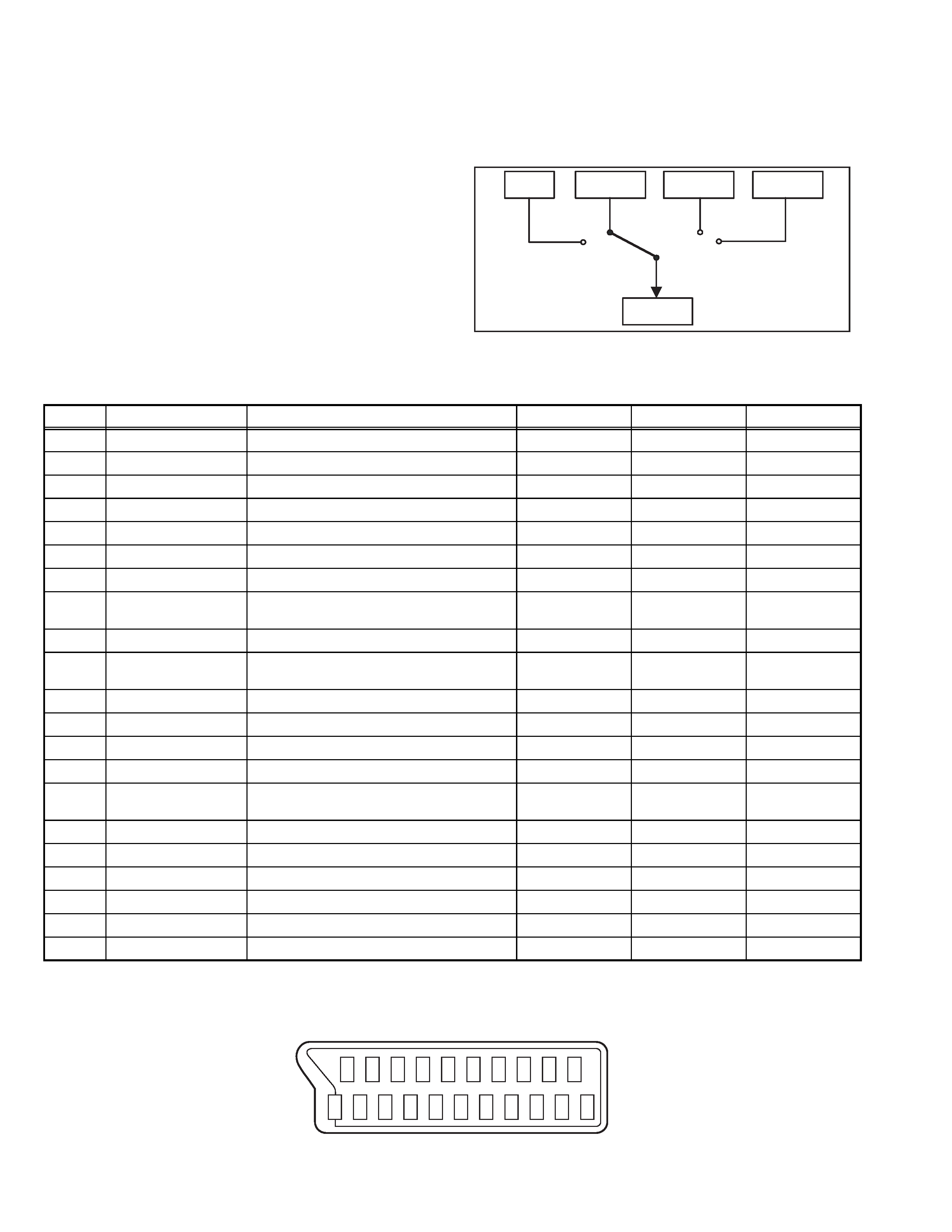
· Users can make VCR dubbing of picture and sound by
controlling the AV selector to select an optional source at the
EXT-2 output shown in figure.
2.2
21-pin Euro connector (SCART) : EXT-1/EXT-2/EXT-3
(P-P= Peak to Peak, B-W= Blanking to white peak)
TV
EXT-1
EXT-3
EXT-2
EXT-4
Pin No.
Signal designation
Matching value
EXT-1
EXT-2
EXT-3
1
AUDIO R output
500mV(rms) (Nominal), Low impedance
Used (TV OUT)
Used (LINE OUT) Not used
2
AUDIO R input
500mV(rms) (Nominal), High impedance
Used (R1)
Used (R2)
Used (R3)
3
AUDIO L output
500mV(rms) (Nominal), Low impedance
Used (TV OUT)
Used (LINE OUT) Not used
4
AUDIO GND
Used
Used
Used
5
GND (B)
Used
Used
Used
6
AUDIO L input
500mV(rms) (Nominal), High impedance
Used (L1)
Used (L2)
Used (L3)
7
B input
700mV(B-W), 75
Used
Used
Not used
8
FUNCTION SW
(SLOW SW)
Low : 0V-3V
High : 8V-12V, High impedance
Used
Used
Used
9
GND (G)
Used
Used
Used
10
SCL / T-V LINK
Not used
Used
(SCL2 / TV-LINK)
Not used
11
G input
700mV(B-W), 75
Used
Used
Not used
12
SDA
Not used
Used (SDA2)
Not used
13
GND (R)
Used
Used
Used
14
GND (YS)
Used
Not used
Not used
15
R / C input
R : 700mV(B-W), 75
C : 300mV(P-P), 75
Used (R)
Used (C2/R)
Used (C3)
16
Ys input (FAST SW)
Low : 0V-0.4V, High : 1V-3V, 75
Used
Used
Not used
17
GND (VIDEO output)
Used
Used
Used
18
GND (VIDEO input)
Used
Used
Used
19
VIDEO output
1V(P-P) (Negative sync), 75
Used (TV OUT)
Used (LINE OUT) Not used
20
VIDEO / Y input
1V(P-P) (Negative sync), 75
Used
Used
Used
21
COMMON GND
Used
Used
Used
20 18 16
14 12 10
8
6
4
2
21 19 17
15 13 11
9
7
5
3
1
[Pin assignment]
(No.52125)1-5
SECTION 3
DISASSEMBLY
3.1
DISASSEMBLY PROCEDURE
3.1.1 REMOVING THE REAR COVER
(1) Unplug the power cord.
(2) Remove the 13 screws [A] as shown in the Fig. 1.
(3) Withdraw the REAR COVER toward you.
3.1.2 REMOVING THE SIDE CONTROL JACK ASS'Y
· Remove the REAR COVER.
(1) Remove the 1 screw [B] as shown in the Fig.1.
(2) While slightly raise the SIDE CONTROL JACK ASSY,
remove the 2 claws under the SIDE CONTROL JACK
ASSY.
(3) Disconnect the connector [F] and [K] as shown in Fig. 2.
3.1.3 REMOVING THE SIDE CONTROL PWB
· Remove the REAR COVER.
· Remove the SIDE CONTROL JACK ASSY.
(1) Remove the 3 claws [C] from back side of the SIDE
CONTROL JACK ASSY as shown in Fig. 2.
(2) Pull out the SIDE CONTROL PWB.
3.1.4 REMOVING THE CHASSIS
· Remove the REAR COVER.
(1) Slightly raise the both sides of the chassis by hand and
remove the 2 claws under the both sides of the CHASSIS
from the front cabinet.
(2) Withdraw the CHASSIS backward.
(If necessary, take off the wire clamp, connectors etc.)
3.1.5 REMOVING THE POWER & DEF. PWB
· Remove the REAR COVER.
· Remove the CHASSIS.
(1) Remove the 3 screws [D] as shown in Fig. 1.
(2) Remove the POWER & DEF. PWB upper.
(If necessary, take off the wire clamp, connectors etc.)
3.1.6 REMOVING THE SIDE SPEAKER
· Remove the REAR COVER.
(1) Remove the 2 screws [E], and remove the SPEAKER
ADAPTER as shown in Fig. 1.
NOTE :
When removing the 2 screws [E] of the speaker holder
remove the lower side screw first, and then remove the
upper one.
(2) Remove the 4 screws [F] attaching the SPEAKER.
(3) Follow the same steps when removing the other hand
SPEAKER.
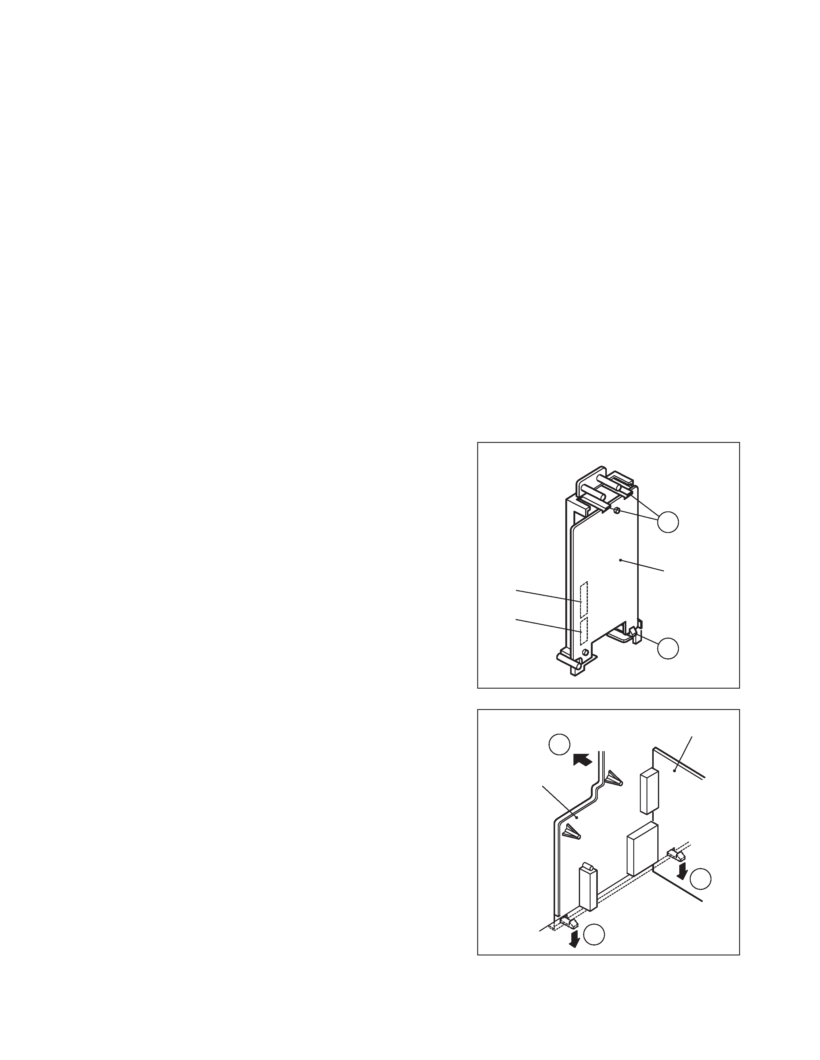
3.1.7 REMOVING THE AV TERMINAL BOARD
· Remove the REAR COVER.
(1) Remove the 3 screws [G] as shown in the Fig. 1.
(2) Remove the 2 claws [H] under the CHASSIS as shown in
Fig. 3.
(3) Remove the AV TERMINAL BOARD slightly in the
direction of arrow [I] as shown in Fig. 3.
3.1.8 CHECKING THE PW BOARD
· To check the back side of the PW Board.
(1) Pull out the CHASSIS. (Refer to REMOVING THE
CHASSIS).
(2) Erect the CHASSIS vertically so that you can easily check
the back side of the PW Board.
CAUTION:
· When erecting the CHASSIS, be careful so that there will be
no contacting with other PW Board.
· Before turning on power, make sure that the wire connector
is properly connected.
· When conducting a check with power supplied, be sure to
confirm that the CRT EARTH WIRE (BRAIDED ASS'Y) is
connected to the CRT SOCKET PW board.
3.1.9 WIRE CLAMPING AND CABLE TYING
(1) Be sure to clamp the wire.
(2) Never remove the cable tie used for tying the wires
together.Should it be inadvertently removed, be sure to tie
the wires with a new cable tie.
Fig.2
Fig.3
SIDE
CONTROL
PWB
F
K
(Back view)
C
C
AV SW PWB
AV
TERMINAL
BOARD
H
I
H