No.51780
AV32X10EUS
AV28X10EUS
AV28X10EKS
AV28X10EIS
1
COPYRIGHT © 2001 VICTOR COMPANY OF JAPAN, LTD.
May. 2001
AV32X10EUS
AV28X10EUS
AV28X10EKS
AV28X10EIS
CONTENTS
! SPECIFICATIONS
2
! SAFETY PRECAUTIONS(EU)
4
! SAFETY PRECAUTIONS(EK/EI)
5
! FEATURES
6
! FUNCTIONS
6
! MAIN DIFFERENCE LIST
7
! SPECIFIC SERVICE INSTRUCTIONS
8
! SERVICE ADJUSTMENTS
14
! PARTS LIST
33
OPERATING INSTRUCTIONS
STANDARD CIRCUIT DIAGRAM
2-1
SERVICE MANUAL
COLOUR TELEVISION
BASIC CHASSIS
MF
No.51780
AV32X10EUS
AV28X10EUS
AV28X10EKS
AV28X10EIS
2
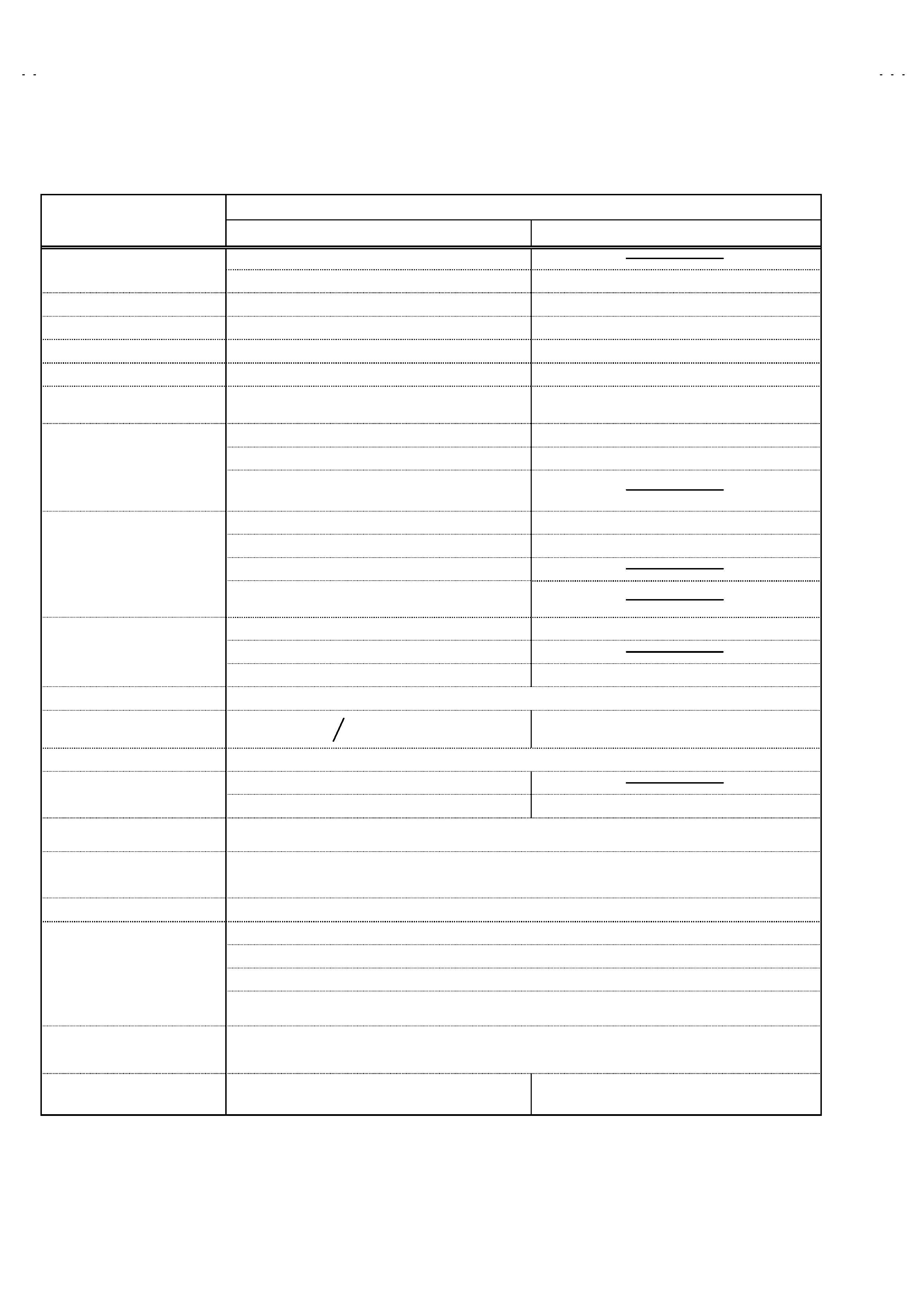
SPECIFICATIONS
Content
Item
AV32X10EUS / AV28X10EUS
AV28X10EKS / AV28X10EIS
(32") : 85.5cm×55.0cm×56.8cm
Dimensions ( W×
×
×
×H×
×
×
×D )
(28") : 78.0cm×50.9cm×49.9cm
78.0cm×50.9cm×49.9cm
Mass
(32") : 54.2kg / (28") : 40.2kg
40.2kg
TV RF System
CCIR ( B/G, D/K, L, L',I)
CCIR ( I )
Colour System
PAL / SECAM / NTSC (Only in EXT mode)
PAL / NTSC (Only in EXT mode)
Stereo System
A2 (B/G, D/K) / NICAM (B/G, I, D/K, L)
NICAM ( I )
Teletext System
Fastext (UK system) / TOP (German system)
WST(world standard system)
Fastext (UK system)
WST(world standard system)
VHF : 47MHz 470MHz
VHF : 47MHz 470MHz ( EI model )
UHF : 470MHz 862MHz
UHF : 470MHz 862MHz ( EK / EI model )
Receiving Frequency
! French cable TV channel of broadcast frequencies
116172MHz & 220469MHz
VIF Carrier : 38.9MHz(B/G, D/K, I, L) / 33.95MHz (L')
VIF Carrier : 38.9MHz
SIF Carrier : 33.4MHz(5.5MHz : B/G)
SIF Carrier : 32.9MHz (6.0MHz )
32.9MHz(6.0MHz : I )
Intermediate Frequency
32.4MHz(6.5MHz : L, D/K)
40.45MHz (6.5MHz : L')
PAL : 4.43MHz
PAL : 4.43MHz
SECAM : 4.40625MHz / 4.25MHz
Colour Sub Carrier Freq.
NTSC : 3.58MHz / 4.43MHz
NTSC : 3.58MHz / 4.43MHz
Power Input
AC 220V240V , 50Hz
Power Consumption
(32")
(28")
183W(Max) , 127W(Avg)
Aerial Input Term
75unbalanced, Coaxial
(32") : Viewable area 76cm ( measured diagonally)
Picture Tube
(28") : Viewable area 66cm ( measured diagonally)
Viewable area 66cm ( measured diagonally)
High Voltage
31.0kV
(at zero beam current)
Speaker
16cm×4cm, Oval type×2
Audio Output
7.5W + 7.5W
EXT-1/EXT-2/EXT-3 (IN/OUT)
21-pin Euro connector (SCART socket)×3
Video : Vp-p 75(RCA pin jack)
Audio(L/R) : 500mVrms(-4dBs), High Impedance (RCA pin jack)
S / Video
Y : 1Vp-p POSITIVE (Negative sync Provided, when terminated with 75)
EXT-4 (Input)
C : 0.3Vp-p (Burst signal, when terminated with 75)
AUDIO OUT (Variable)
01Vrms, Low Impedance (RCA pin jack×2)
Headphone jack
Stereo mini jack (3.5mm )
Remote Control Unit
RM-C54 (AAA/R03 dry cell battery×2)
RM-C55 (AAA/R03 dry cell battery×2)
Design & specifications are subject to change without notice.
+1.0kV
-1.5kV
183W(Max)
127W(Avg)
189W(Max)
140W(Avg)
No.51780
AV32X10EUS
AV28X10EUS
AV28X10EKS
AV28X10EIS
3
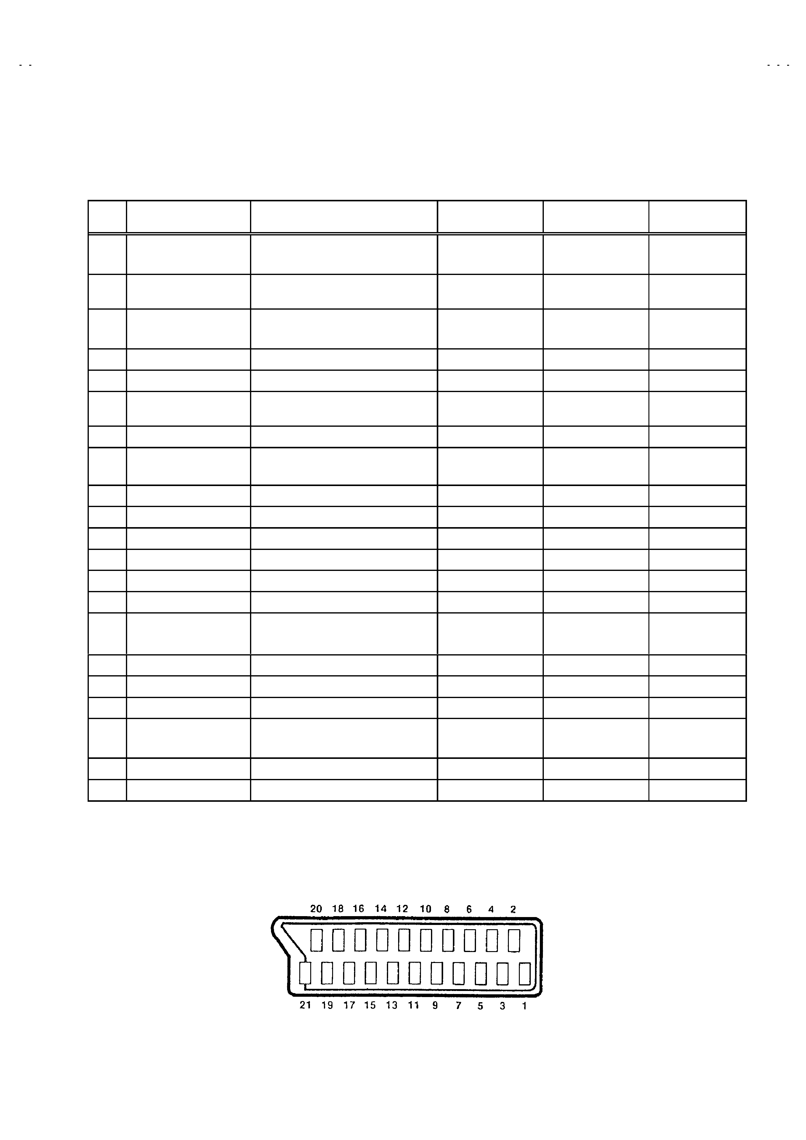
21-pin Euro connector (SCART socket) : EXT-1 / EXT-2 / EXT-3
(P-P= Peak to Peak, B-W= Blanking to white peak)
Pin
No.
Signal Designation
Matching Value
EXT-1
EXT-2
EXT-3
1
AUDIO R output
500mVrms(Nominal),
Low impedance
(TV OUT)
(LINE OUT)
NC
2
AUDIO R input
500mVrms(Nominal),
High impedance
3
AUDIO L output
500mVrms(Nominal),
Low impedance
(TV OUT)
(LINE OUT)
NC
4
AUDIO GND
5
GND (B)
6
AUDIO L input
500mVrms(Nominal),
High impedance
7B input
700mV
B-W, 75
NC
8
FUNCTON SW
(SLOW SW)
Low : 0-3V, High : 8-12V, High
impedance
9
GND (G)
10
SCL3
NC
NC
11
G input
700mV
B-W, 75
NC
12
SDA3
NC
NC
13
GND (R)
14
GND (Y
S)
NC
15
R / C input
R : 700mV
B-W, 75
C : 300mV
P-P, 75
(only R)
(only C)
16
Ys input
Low : 0 - 0.4, High : 1 - 3V, 75
NC
17
GND(VIDEO output)
18
GND(VIDEO input)
19
VIDEO output
1V
P-P(Negative going sync), 75
(TV)
(LINE OUT)
NC
20
VIDEO / Y input
1V
P-P(Negative going sync), 75
21
COMMON GND
[Pin assignment]
No.51780
AV32X10EUS
AV28X10EUS
4
SAFETY PRECAUTIONS
1.
The design of this product contains special hardware, many
circuits and components specially for safety purposes. For
continued protection, no changes should be made to the original
design unless authorized in writing by the manufacturer.
Replacement parts must be identical to those used in the original
circuits. Service should be performed by qualified personnel
only.
2.
Alterations of the design or circuitry of the products should not be
made. Any design alterations or additions will void the
manufacturer's warranty and will further relieve the manufacturer
of responsibility for personal injury or property damage resulting
therefrom.
3.
Many electrical and mechanical parts in the products have
special safety-related characteristics. These characteristics are
often not evident from visual inspection nor can the protection
afforded by them necessarily be obtained by using replacement
components rated for higher voltage, wattage, etc. Replacement
parts which have these special safety characteristics are
identified in the parts list of Service manual. Electrical
components having such features are identified by shading
on the schematics and by (!
!
!
!) on the parts list in Service
manual. The use of a substitute replacement which does not
have the same safety characteristics as the recommended
replacement part shown in the parts list of Service manual may
cause shock, fire, or other hazards.
4.
Don't short between the LIVE side ground and ISOLATED
(NEUTRAL) side ground or EARTH side ground when
repairing.
Some model's power circuit is partly different in the GND. The
difference of the GND is shown by the LIVE : (") side GND, the
ISOLATED(NEUTRAL) : (#) side GND and EARTH : ($) side
GND.
Don't
short
between
the
LIVE
side
GND
and
ISOLATED(NEUTRAL) side GND or EARTH side GND and
never measure with a measuring apparatus (oscilloscope etc.)
the LIVE side GND and ISOLATED(NEUTRAL) side GND or
EARTH side GND at the same time.
If above note will not be kept, a fuse or any parts will be broken.
5.
If any repair has been made to the chassis, it is recommended
that the B1 setting should be checked or adjusted (See
ADJUSTMENT OF B1 POWER SUPPLY).
6.
The high voltage applied to the picture tube must conform with
that specified in Service manual. Excessive high voltage can
cause an increase in X-Ray emission, arcing and possible
component damage, therefore operation under excessive high
voltage conditions should be kept to a minimum, or should be
prevented. If severe arcing occurs, remove the AC power
immediately and determine the cause by visual inspection
(incorrect installation, cracked or melted high voltage harness,
poor soldering, etc.). To maintain the proper minimum level of
soft X-Ray emission, components in the high voltage circuitry
including the picture tube must be the exact replacements or
alternatives approved by the manufacturer of the complete
product.
7.
Do not check high voltage by drawing an arc. Use a high voltage
meter or a high voltage probe with a VTVM. Discharge the
picture tube before attempting meter connection, by connecting
a clip lead to the ground frame and connecting the other end of
the lead through a 10k
" 2W resistor to the anode button.
8.
When service is required, observe the original lead dress. Extra
precaution should be given to assure correct lead dress in the
high voltage circuit area. Where a short circuit has occurred,
those components that indicate evidence of overheating should
be replaced. Always use the manufacturer's replacement
components.
9.
Isolation Check
(Safety for Electrical Shock Hazard)
After re-assembling the product, always perform an isolation
check on the exposed metal parts of the cabinet (antenna
terminals, video/audio input and output terminals, Control knobs,
metal cabinet, screwheads, earphone jack, control shafts, etc.)
to be sure the product is safe to operate without danger of
electrical shock.
(1) Dielectric Strength Test
The isolation between the AC primary circuit and all metal parts
exposed to the user, particularly any exposed metal part having a
return path to the chassis should withstand a voltage of 3000V
AC (r.m.s.) for a period of one second.
(. . . . Withstand a voltage of 1100V AC (r.m.s.) to an appliance
rated up to 120V, and 3000V AC (r.m.s.) to an appliance rated
200V or more, for a period of one second.)
This method of test requires a test equipment not generally found
in the service trade.
(2) Leakage Current Check
Plug the AC line cord directly into the AC outlet (do not use a line
isolation transformer during this check.). Using a "Leakage
Current Tester", measure the leakage current from each exposed
metal part of the cabinet, particularly any exposed metal part
having a return path to the chassis, to a known good earth
ground (water pipe, etc.). Any leakage current must not exceed
0.5mA AC (r.m.s.).
However, in tropical area, this must not exceed 0.2mA AC
(r.m.s.).
"
"
"
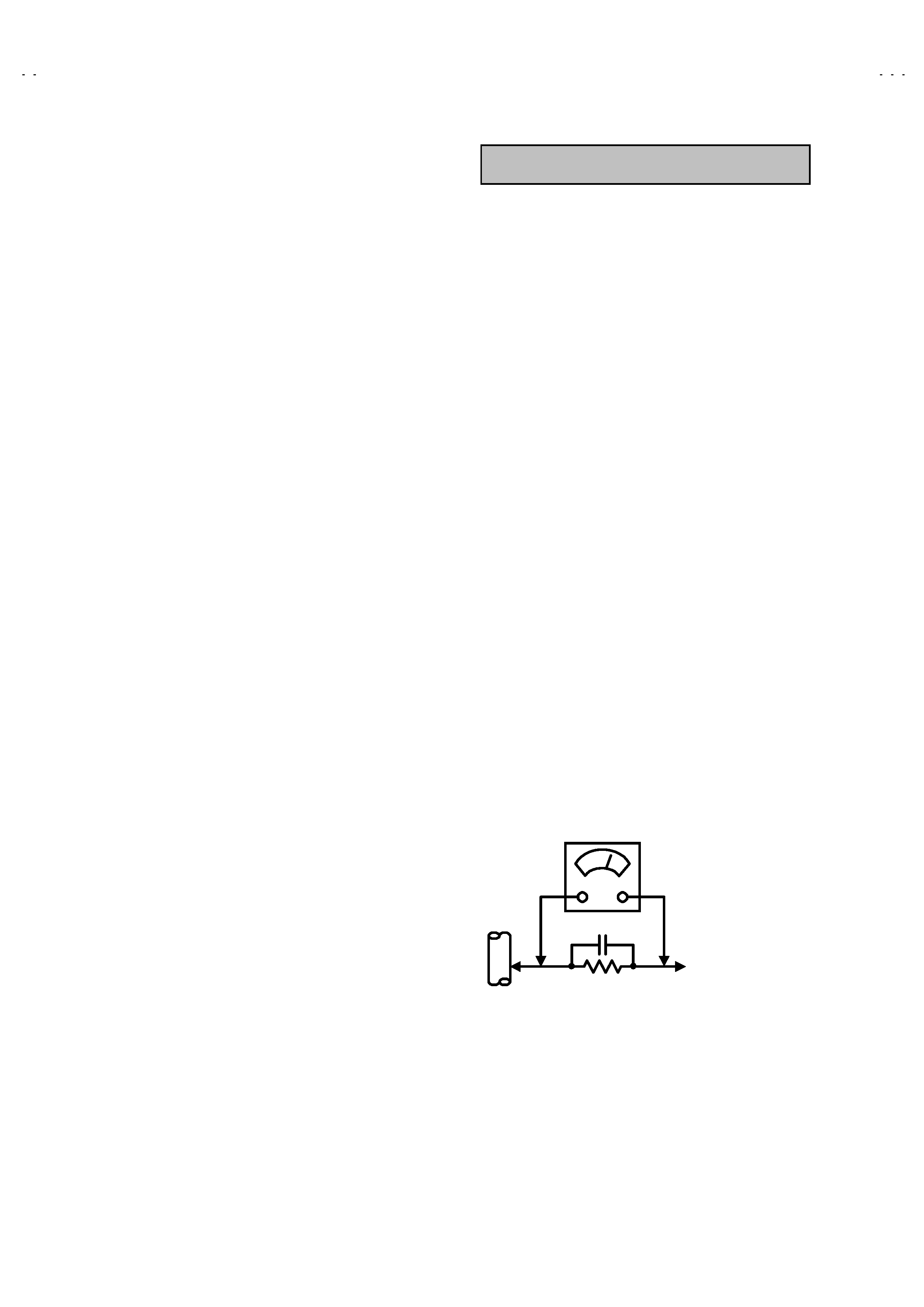
" Alternate Check Method
Plug the AC line cord directly into the AC outlet (do not use a line
isolation transformer during this check.). Use an AC voltmeter
having 1000 ohms per volt or more sensitivity in the following
manner. Connect a 1500
" 10W resistor paralleled by a 0.15#F
AC-type capacitor between an exposed metal part and a known
good earth ground (water pipe, etc.). Measure the AC voltage
across the resistor with the AC voltmeter. Move the resistor
connection to each exposed metal part, particularly any exposed
metal part having a return path to the chassis, and measure the
AC voltage across the resistor. Now, reverse the plug in the AC
outlet and repeat each measurement. Any voltage measured
must not exceed 0.75V AC (r.m.s.).
This corresponds to 0.5mA
AC (r.m.s.).
However, in tropical area, this must not exceed 0.3V AC (r.m.s.).
This corresponds to 0.2mA AC (r.m.s.).
0.15F AC-TYPE
1500 " 10W
GOOD EARTH GROUND
PLACE THIS PROBE
ON EACH EXPOSED
METAL PART
AC VOLTMETER
(HAVING 1000 "/V,
OR MORE SENSITIVITY)
AV32X10EUS / AV28X10EUS

No.51780
AV28X10EKS
AV28X10EIS
5
SAFETY PRECAUTIONS
1.
The design of this product contains special hardware and many
circuits and components specially for safety purposes. For
continued protection, no changes should be made to the original
design unless authorized in writing by the manufacturer.
Replacement parts must be identical to those used in the original
circuits. Service should be performed by qualified personnel
only.
2.
Alterations of the design or circuitry of the product should not be
made. Any design alterations or additions will void the
manufacturer's warranty and will further relieve the manufacturer
of responsibility for personal injury or property damage resulting
therefrom.
3.
Many electrical and mechanical parts in the product have special
safety-related characteristics. These characteristics are often not
evident from visual inspection nor can the protection afforded by
them necessary be obtained by using replacement components
rated for higher voltage, wattage, etc. Replacement parts which
have these special safety characteristics are identified in the
Parts List of Service Manual. Electrical components having such
features are identified by shading on the schematics and by (!)
on the Parts List in the Service Manual. The use of a substitute
replacement
which
does
not
have
the
same
safety
characteristics as the recommended replacement part shown in
the Parts List of Service Manual may cause shock, fire, or other
hazards.
4.
The leads in the products are routed and dressed with ties,
clamps, tubing's, barriers and the like to be separated from live
parts, high temperature parts, moving parts and / or sharp edges
for the prevention of electric shock and fire hazard. When
service is required, the original lead routing and dress should be
observed, and it should be confirmed that they have been
returned to normal, after re-assembling.
WARNING
1.
The equipment has been designed and manufactured to meet international safety standards.
2.
It is the legal responsibility of the repairer to ensure that these safety standards are maintained.
3.
Repairs must be made in accordance with the relevant safety standards.
4.
It is essential that safety critical components are replaced by approved parts.
5.
If mains voltage selector is provided, check setting for local voltage.
AV28X10EKS / AV28X10EIS