No.51806
AV-27GFH
1
COPYRIGHT © 2001 VICTOR COMPANY OF JAPAN, LTD.
Jun. 2001
AV-27GFH/Z
CONTENTS
! SPECIFICATIONS
2
! SAFETY PRECAUTIONS
3
! FEATURES
4
! SPECIFIC SERVICE INSTRUCTIONS
6
! SERVICE ADJUSTMENTS
15
! PARTS LIST
33
OPERATING INSTRUCTIONS
STANDARD CIRCUIT DIAGRAM (APPENDIX)
2-1
BASIC CHASSIS
GF
SERVICE MANUAL
COLOR TELEVISION
(OPTION)
No.51806
AV-27GFH
2
SPECIFICATIONS
Items
Contents
Dimensions (W×
×
×
×H×
×
×
×D)
25-3/4"×23-3/8"×20-1/2" (65.4cm×59.1cm×51.8cm)
Mass
79.9Ibs / (36.3kg)
TV System and Color system
TV RF System
Color System
Sound System
CCIR(M)
NTSC
BTSC (Multi Channel Sound)
TV Receiving Channels and Frequency
VL Band
VH Band
UHF Band
(0206) 54MHz88MHz
(0713) 174MHz216MHz
(1469) 470MHz806MHz
CATV Receiving Channels and Frequency
Low Band
High Band
Mid Band
Super Band
Hyper Band
Ultra Band
Sub Mid Band
(0206, A-8) by (0206&01)
(0713) by (0713)
(A1) by (1422)
(JW) by (2336)
(W+1W+28) by (3764)
(W+29W+84) by (65125)
(A8, A4A1) by (01, 9699)
TV/CATV Total Channel
181 Channels
Intermediate Frequency
Video IF Carrier
Sound IF Carrier
Color Sub Carrier
45.75 MHz
41.25 MHz (4.5MHz)
3.58 MHz
Power Input
120V AC, 60Hz
Power Consumption
120W / 1.7A
Picture Tube
27" (68cm) measured diagonally, Full Square
High Voltage
29kV±1.3kV (at zero beam current)
Speaker
2"×4-3/4" / 5×12cm oval×2
Audio Power Output
3W+3W
Input (Front & Rear)
Video
: 1Vp-p 75 (RCA pin jack)
Audio
: 500mVrms (-4dBs), High Impedance (RCA pin jack)
S-Video Y : 1Vp-p positive (negative sync provided, when terminated with 75)
C : 0.286Vp-p (burst signal, when terminated with 75)
Modular Jack
Digital Interface for Command box.
Antenna terminal
75 (VHF/UHF) Terminal, F-Type Connector
Remote Control Unit (OPTIONAL)
RM-C205-1A (AA/R6/UM-3 battery×2)
Design & specifications are subject to change without notice.
(54MHz804MHz)
No. 51806
AV-27GFH
3
SAFETY PRECAUTIONS
1.
The design of this product contains special hardware, many
circuits and components specially for safety purposes. For
continued protection, no changes should be made to the
original design unless authorized in writing by the manufacturer.
Replacement parts must be identical to those used in the
original circuits. Service should be performed by qualified
personnel only.
2.
Alterations of the design or circuitry of the products should not
be made. Any design alterations or additions will void the
manufacturer's
warranty
and
will
further
relieve
the
manufacturer of responsibility for personal injury or property
damage resulting therefrom.
3.
Many electrical and mechanical parts in the products have
special safety-related characteristics. These characteristics are
often not evident from visual inspection nor can the protection
afforded
by
them
necessarily
be
obtained
by
using
replacement components rated for higher voltage, wattage, etc.
Replacement
parts
which
have
these
special
safety
characteristics are identified in the parts list of Service manual.
Electrical components having such features are identified
by shading on the schematics and by (!
!
!
!) on the parts list
in Service manual. The use of a substitute replacement which
does not have the same safety characteristics as the
recommended replacement part shown in the parts list of
Service manual may cause shock, fire, or other hazards.
4.
Use isolation transformer when hot chassis.
The chassis and any sub-chassis contained in some products
are connected to one side of the AC power line. An isolation
transformer of adequate capacity should be inserted between
the product and the AC power supply point while performing
any service on some products when the HOT chassis is
exposed.
5.
Don't short between the LIVE side ground and ISOLATED
(NEUTRAL) side ground or EARTH side ground when
repairing.
Some model's power circuit is partly different in the GND. The
difference of the GND is shown by the LIVE : (") side GND,
the ISOLATED(NEUTRAL) : (#) side GND and EARTH : ($)
side GND. Don't short between the LIVE side GND and
ISOLATED(NEUTRAL) side GND or EARTH side GND and
never measure with a measuring apparatus (oscilloscope etc.)
the LIVE side GND and ISOLATED(NEUTRAL) side GND or
EARTH side GND at the same time.
If above note will not be kept, a fuse or any parts will be broken.
6.
If any repair has been made to the chassis, it is recommended
that the B1 setting should be checked or adjusted (See
ADJUSTMENT OF B1 POWER SUPPLY).
7.
The high voltage applied to the picture tube must conform with
that specified in Service manual. Excessive high voltage can
cause an increase in X-Ray emission, arcing and possible
component damage, therefore operation under excessive high
voltage conditions should be kept to a minimum, or should be
prevented. If severe arcing occurs, remove the AC power
immediately and determine the cause by visual inspection
(incorrect installation, cracked or melted high voltage harness,
poor soldering, etc.). To maintain the proper minimum level of
soft X-Ray emission, components in the high voltage circuitry
including the picture tube must be the exact replacements or
alternatives approved by the manufacturer of the complete
product.
8.
Do not check high voltage by drawing an arc. Use a high
voltage meter or a high voltage probe with a VTVM. Discharge
the picture tube before attempting meter connection, by
connecting a clip lead to the ground frame and connecting the
other end of the lead through a 10k 2W resistor to the anode
button.
9.
When service is required, observe the original lead dress.
Extra precaution should be given to assure correct lead dress
in the high voltage circuit area. Where a short circuit has
occurred,
those
components
that
indicate
evidence
of
overheating
should
be
replaced.
Always
use
the
manufacturer's replacement components.
10. Isolation Check
(Safety for Electrical Shock Hazard)
After re-assembling the product, always perform an isolation
check on the exposed metal parts of the cabinet (antenna
terminals, video/audio input and output terminals, Control
knobs, metal cabinet, screw heads, earphone jack, control
shafts, etc.) to be sure the product is safe to operate without
danger of electrical shock.
(1) Dielectric Strength Test
The isolation between the AC primary circuit and all metal parts
exposed to the user, particularly any exposed metal part having
a return path to the chassis should withstand a voltage of
1100V AC (r.m.s.) for a period of one second.
(. . . . Withstand a voltage of 1100V AC (r.m.s.) to an appliance
rated up to 120V, and 3000V AC (r.m.s.) to an appliance rated
200V or more, for a period of one second.)
This method of test requires a test equipment not generally
found in the service trade.
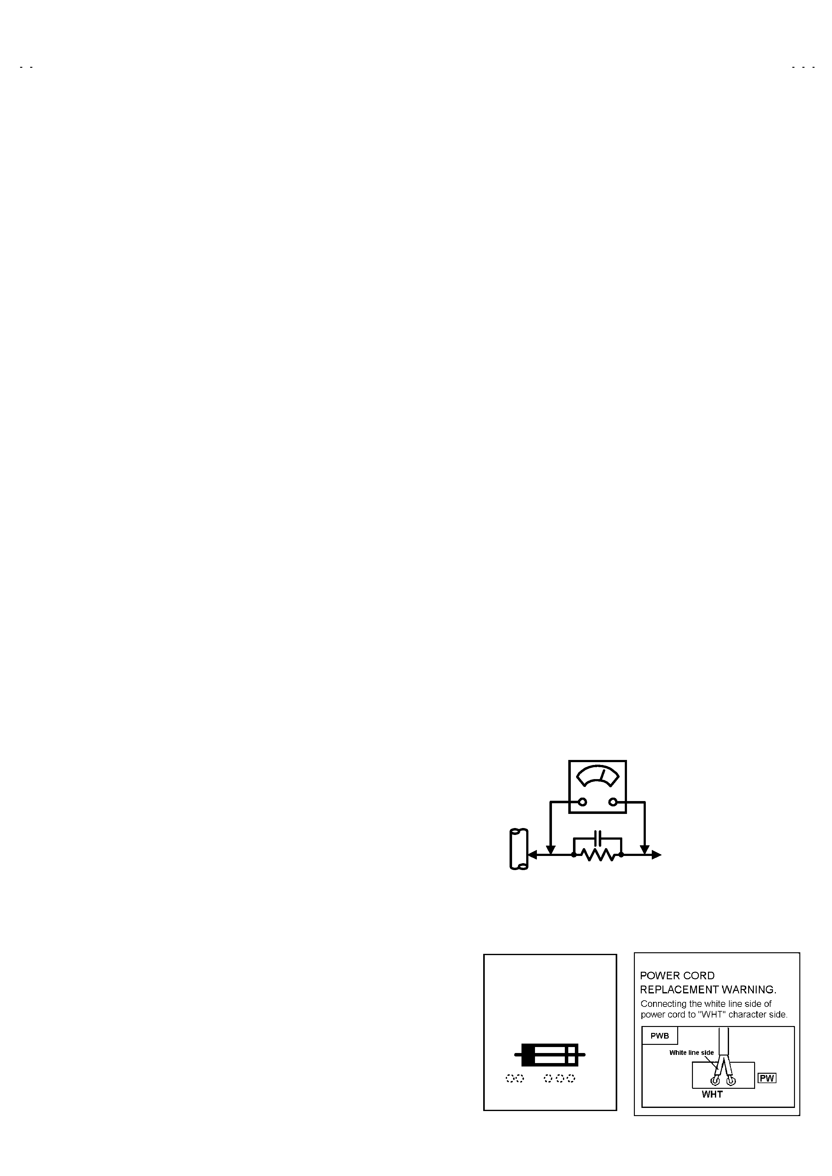
(2) Leakage Current Check
Plug the AC line cord directly into the AC outlet (do not use a
line isolation transformer during this check.). Using a "Leakage
Current Tester", measure the leakage current from each
exposed metal part of the cabinet, particularly any exposed
metal part having a return path to the chassis, to a known good
earth ground (water pipe, etc.). Any leakage current must not
exceed 0.5mA AC (r.m.s.).
However, in tropical area, this must not exceed 0.2mA AC
(r.m.s.).
"
"
"
" Alternate Check Method
Plug the AC line cord directly into the AC outlet (do not use a
line isolation transformer during this check.). Use an AC
voltmeter having 1000 ohms per volt or more sensitivity in the
following manner. Connect a 1500 10W resistor paralleled
by a 0.15F AC-type capacitor between an exposed metal
part and a known good earth ground (water pipe, etc.).
Measure the AC voltage across the resistor with the AC
voltmeter. Move the resistor connection to each exposed metal
part, particularly any exposed metal part having a return path to
the chassis, and measure the AC voltage across the resistor.
Now, reverse the plug in the AC outlet and repeat each
measurement. Any voltage measured must not exceed 0.75V
AC (r.m.s.).
This corresponds to 0.5mA AC (r.m.s.).
However, in tropical area, this must not exceed 0.3V AC
(r.m.s.).
This corresponds to 0.2mA AC (r.m.s.).
0.15F AC-TYPE
1500 10W
GOOD
EARTH
GROUND
PLACE THIS PROBE
ON EACH EXPOSED
METAL PART
AC VOLTMETER
(HAVING 1000 /V,
OR MORE SENSITIVITY)
11. High voltage hold down circuit check.
After repair of the high voltage hold down circuit, this circuit
shall be checked to operate correctly.
See item "How to check the high voltage hold down
circuit".
A
V
This mark shows a fast
operating fuse, the
letters indicated below
show the rating.
No.51806
AV-27GFH
4
FEATURES
" New chassis design enables use of a main board with simplified
circuitry.
" Digital comb filter Improved picture quality.
" Full-square CRT (cathode ray tube) reproduces fine textured
picture in every detail.
" With Digital Interface (modular jack) for OCC box.
" Closed-caption broadcasts can be viewed.
" With AUDIO / S-VIDEO / VIDEO INPUT terminal.
" S-VIDEO input terminal for taking best advantage of Super VHS.
" Built-in V-CHIP system.
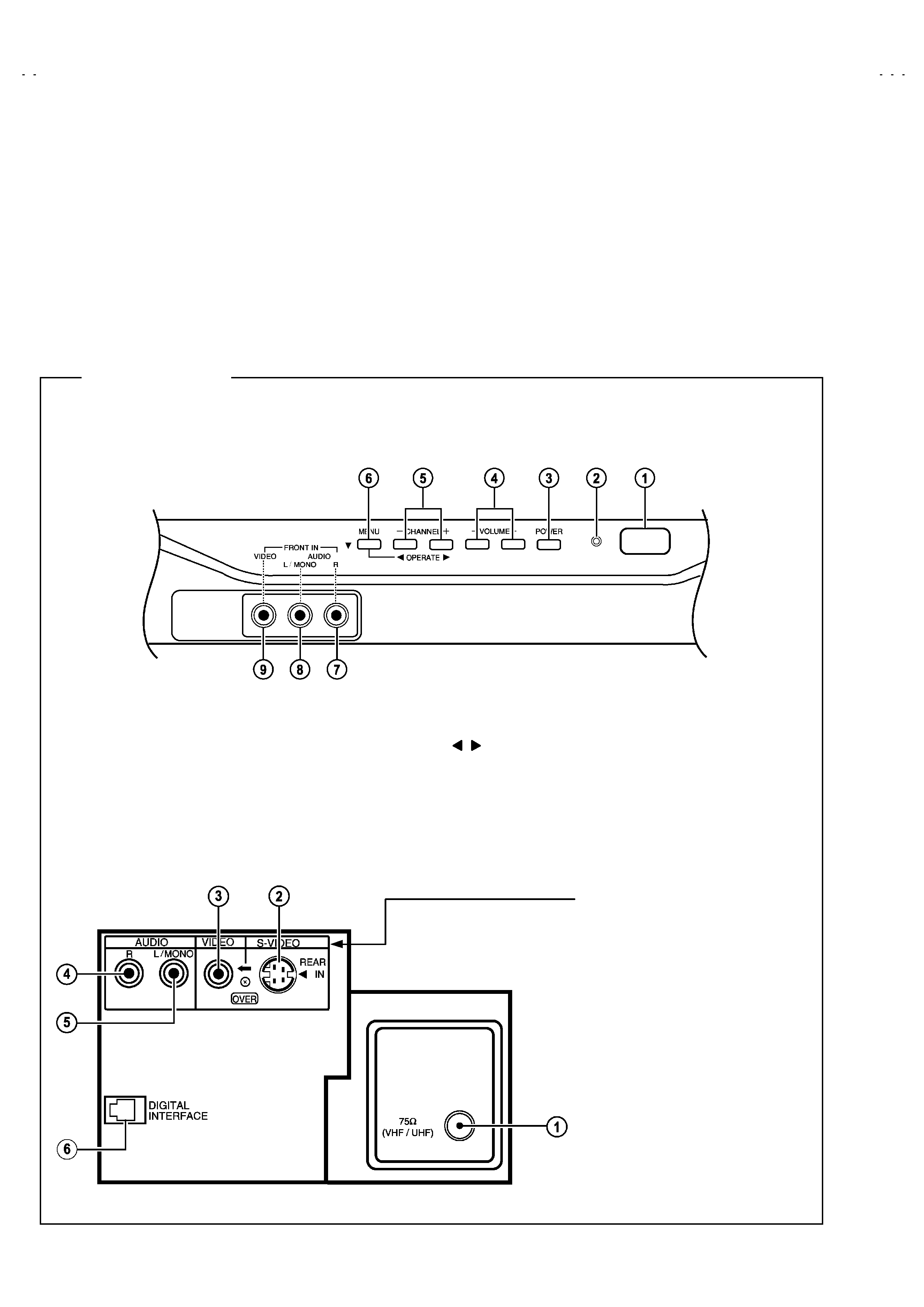
FRONT PANEL
REMOTE CONTROL SENSOR
ON-TIMER INDICATOR
POWER SWICH BUTTON
VOLUME(-/+) BUTTON
CH (-/+) & OPERATE(
) BUTTON
MENU / WORLD CLOCK BUTTON
AUDIO-INPUT(R) Terminal
AUDIO-INPUT(L/MONO) Terminal
VIDEO INPUT Terminal
REAR PANEL
U/V ANT. Terminal
S-VIDEO INPUT Terminal
VIDEO INPUT Terminal
AUDIO(R) INPUT Terminal
AUDIO(L/MONO) INPUT Terminal
DIGITAL INTERFACE Terminal
Modular connector : used to connect
on command box.
FUNCTIONS
A/V Input Terminal
!!!! Used to connect audio/video devices like
VCRs, DVD, players, stereo amplifiers,
game consoles, ...etc.
/
No.51806
AV-27GFH
5
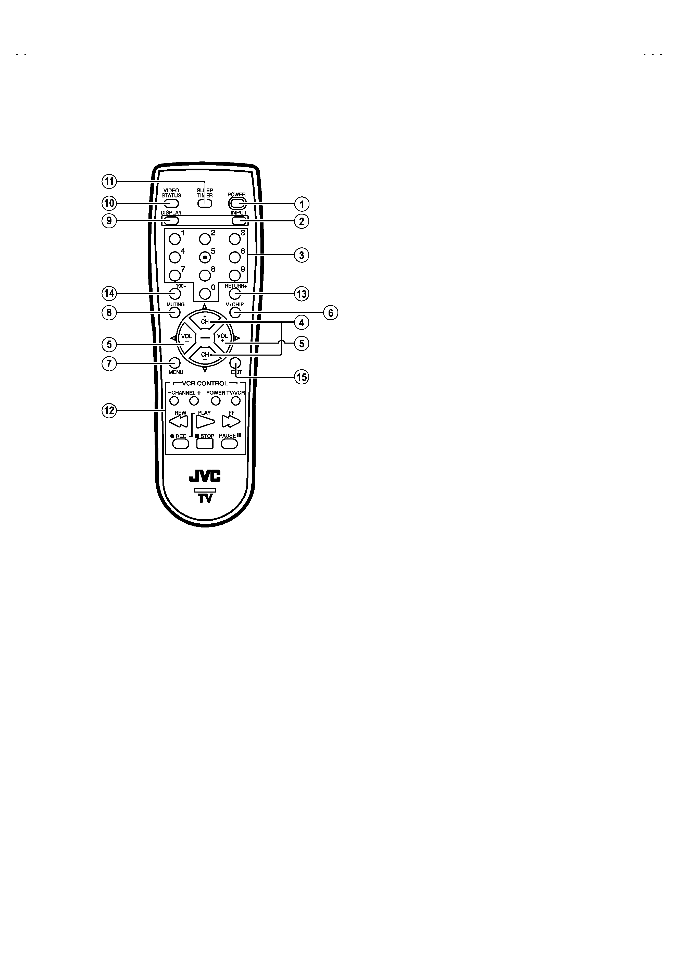
REMOTE CONTROL UNIT (OPTIONAL : RM-C205)
POWER Key
!!!! TV ON or OFF.
INPUT SELECT Key
!!!! Selects the Input source for TV.
DIRECT CH Key
!!!! CH. select.
UP/DOWN CH Key.
!!!! CH. select.
VOL(-/+) Key
!!!! Vol. level control & setup menu setting.
V-CHIP Key
!!!! V-CHIP setting : ON / OFF or BLOCK setting of each RATING.
MENU Key
!!!! Press MENU to activate the on screen menu system.
MUTING Key
!!!! Instantly turns the Vol. down completely.
DISPLAY Key
!!!! Shows the CH. & AV input.
VIDEO STATUS Key
!!!! Use this key to enter the SETUP MENU only.
SLEEP TIMER Key
!!!! Turn the TV-off for you after you fall sleep.
VCR Control
RETURN
+ Key
100
+ Key
!!!! Use the 100+ Key to directly access channels.
EXIT Key
!!!! To leave a menu screen.