VICTOR COMPANY OF JAPAN, LIMITED
CONTENTS
PREPARATION . . . . . . . . . . . . . . . . . . . . . . . . . . . . . 2
BASIC OPERATION . . . . . . . . . . . . . . . . . . . . . . . . . 6
AV COMPU LINK. . . . . . . . . . . . . . . . . . . . . . . . . . . . 8
REMOTE CONTROL BUTTONS AND FUNCTIONS
. . . . . . . . . . . . . . . . . . . . . . . . . . . . . . . . . . . . . . . . . . 9
MENU OPERATION . . . . . . . . . . . . . . . . . . . . . . . . 14
PICTURE SETTING. . . . . . . . . . . . . . . . . . . . . . . . . 15
PICTURE FEATURES . . . . . . . . . . . . . . . . . . . . . . . 16
SOUND SETTING . . . . . . . . . . . . . . . . . . . . . . . . . . 18
FEATURES . . . . . . . . . . . . . . . . . . . . . . . . . . . . . . . 20
INSTALL . . . . . . . . . . . . . . . . . . . . . . . . . . . . . . . . . 23
DEMO . . . . . . . . . . . . . . . . . . . . . . . . . . . . . . . . . . . 27
CONNECTING THE EXTERNAL DEVICES . . . . . . 28
TV BUTTONS AND PARTS. . . . . . . . . . . . . . . . . . . 30
CH/CC NUMBER . . . . . . . . . . . . . . . . . . . . . . . . . . . 32
BROADCASTING SYSTEMS . . . . . . . . . . . . . . . . . 33
TROUBLESHOOTING. . . . . . . . . . . . . . . . . . . . . . . 34
SPECIFICATIONS . . . . . . . . . . . . . . . . . . . Back cover
COLOUR TELEVISION
AV-29R9B
AV-29R9
AV-25P9
WARNING:
TO PREVENT FIRE OR SHOCK HAZARD, DO NOT EX-
POSE THIS APPLIANCE TO RAIN OR MOISTURE.
CAUTION:
TO ENSURE PERSONAL SAFETY, OBSERVE THE
FOLLOWING RULES REGARDING THE USE OF THIS
UNIT.
1. Operate only from the power source specified on
the unit.
2. Avoid damaging the AC plug and power cord.
3. Avoid improper installation and never position the
unit where good ventilation is unattainable.
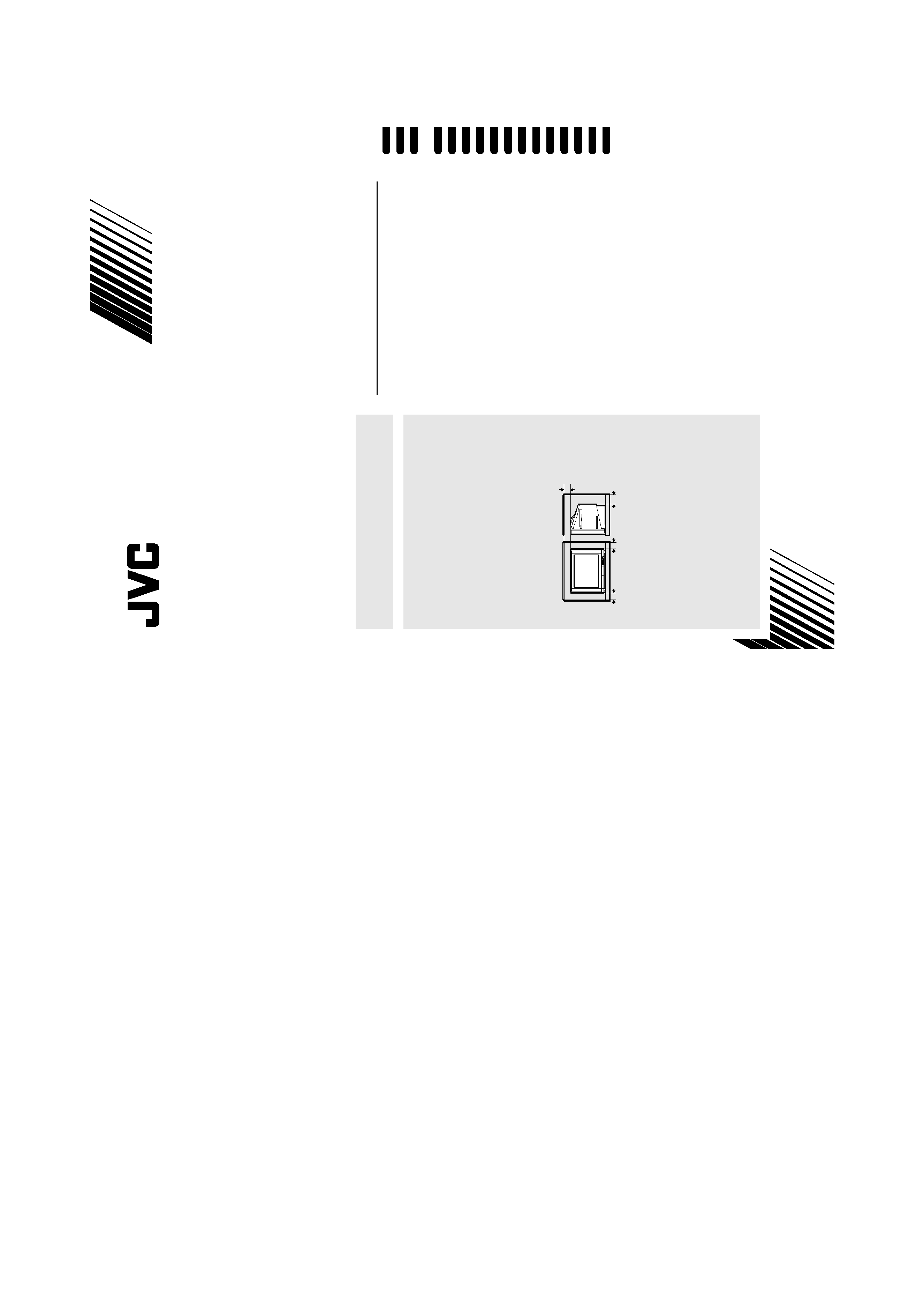
When installing this television, distance recommen-
dations must be maintained between the floor and
wall, as well as instalment in a tightly enclosed area
or piece of furniture. Adhere to the minimum dis-
tance guidelines shown for safe operation.
4. Do not allow objects or liquid into the cabinet openings.
5. In the event of a fault, unplug the unit and call a
service technician. Do not attempt to repair it your-
self or remove the rear cover.
6. For AV-29R9B and AV-29R9 only:
The surface of the TV screen is coated with a thin
film which can easily be damaged. Be very careful
with it when handling the TV.
Should the TV screen become soiled, wipe it with a
soft dry cloth. Never rub it forcefully. Never use any
cleaner or detergent on it.
When you don't use this TV set for a long period of time,
be sure to disconnect the power plug from the AC socket.
15 cm
10 cm
10 cm
15 cm
Instructions
Thank you for buying this JVC colour television.
To make sure you understand how to use your new TV,
please read this manual thoroughly before you begin.
Design and specifications subject to change without notice.
Pictures displayed on the screen using this TV's ZOOM functions should not be shown for any commercial or demonstration pur-
pose in public places (cafes, hotels, etc.) without the consent of the owners of copyright of the original picture sources, as this
constitutes an infringement of copyright.
Model
Item
AV-29R9B
AV-29R9
AV-25P9
Broadcasting systems
B, G, I, D, K, K1, M
Colour systems
PAL, SECAM, NTSC 3.58 / 4.43 MHz
Channels and frequencies
VHF low channel (VL)
= 46.25 to 168.25 MHz
VHF high channel (VH)
= 175.25 to 463.25 MHz
UHF channel (U)
= 471.25 to 863.25 MHz
sReceives cable channels in mid band (X to Z, S1 to S10), super band (S11 to S20) and hyper
band (S21 to S41).
Sound-multiplex systems
A2, NICAM(B/G, I, D/K) system
Power requirements
AC 110 to 240 V, 50 / 60 Hz (operating AC 90 to 260 V, 50 / 60 Hz)
Power consumption
163 W
137 W
119 W
Screen size
(measured diagonally)
Picture tube 73 cm
Visible area 68 cm
Picture tube 65cm
Visible area 60cm
Audio output
Rated Power output:
15 W + 15 W + 5 W
Rated Power output:
10 W + 10 W
Speakers
10 cm round
× 2,
3.5 cm round
× 2
(4cm
× 12cm) oval × 1
10 cm round
× 2
VIDEO-1 terminal
RCA connector
× 3, S-VIDEO connector × 1
· Video input, S-VIDEO (Y/C) input and Audio L/R inputs are available.
VIDEO-2 terminal
RCA connector
× 3
· Video input and Audio L/R inputs are available.
VIDEO-3 COMPONENT
terminal
RCA connector
× 5
· Video input, Component video (Y/CB/CR) input and Audio L/R inputs are available.
VIDEO-4 terminal
RCA connector
× 3, S-VIDEO connector × 1
· Video input, S-VIDEO (Y/C) input and Audio L/R inputs are
available.
RCA connector
× 3
· Video input and Audio L/R
inputs are available.
OUTPUT terminal
RCA connector
× 3
· Video output and Audio L/R outputs are available.
Headphone jack
Stereo mini-jack (3.5 mm in diameter)
Dimensions (W
× H × D)
732 mm
× 588 mm × 508 mm
655 mm
× 530.5 mm × 465 mm
Weight
52 kg
36 kg
Accessories
Remote control unit RM-C114
× 1
AA/R6 dry cell battery
× 2
Matching aerial adapter
× 1
Remote control unit RM-C115
× 1
AA/R6 dry cell battery
× 2
Matching aerial adapter
× 1
© 2000 VICTOR COMPANY OF JAPAN, LIMITED
LCT0816-001A-H
0600-T-AB-JET
AV-29R9B/A
V-29R9/A
V-25P9
s
s
s
s
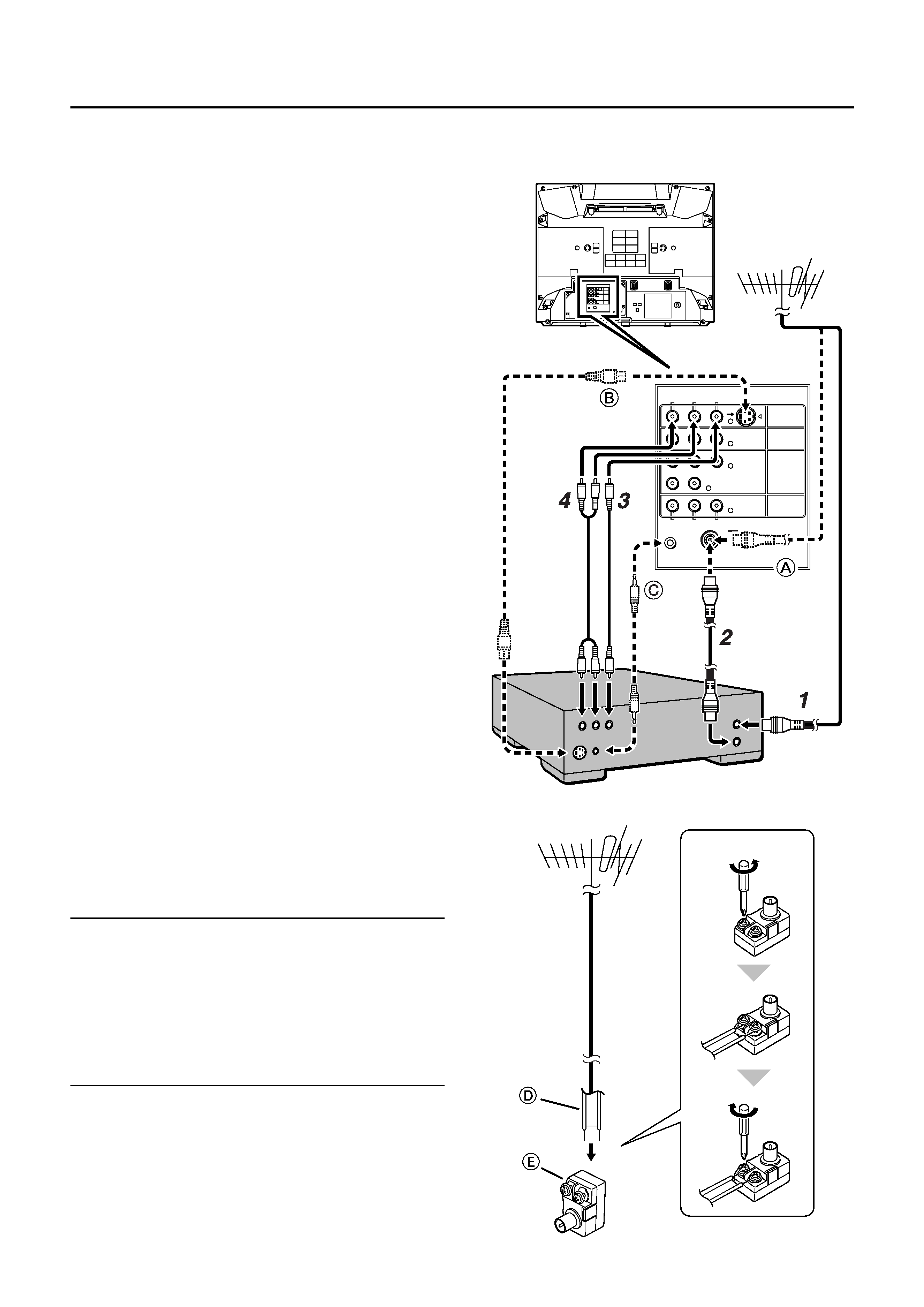
If not connecting a VCR to the TV:
Connect the aerial cable to the TV's aerial socket (see
A in
the illustration).
1 Connect the aerial cable to the VCR's
ANT. IN (aerial input) socket.
2 Connect the VCR's RF OUT (aerial out-
put) socket and the TV's aerial socket
with an RF cable (75-ohm coaxial ca-
ble).
3 Connect the VCR's VIDEO OUT (video
output) jack and the TV's VIDEO jack
with a video cable.
To connect a VCR to the TV with an S-VIDEO
cable:
Connect the VCR's S-VIDEO OUT (S-VIDEO output)
connector and the TV's S connector with an S-VIDEO
cable, instead of connecting with a video cable (see
B in
the illustration).
Note that the connection with a video cable will be ig-
nored in case you connect a VCR to the TV with both vid-
eo cable and S-VIDEO cable.
4 Connect the VCR's AUDIO OUT (audio
L/R output) jacks and the TV's AUDIO
jacks (L/MONO and R) with an audio ca-
ble.
If the VCR's audio output is in mono:
Connect the VCR's AUDIO OUT (audio output) jack and
the TV's AUDIO L/MONO jack with an audio cable.
If the VCR is equipped with an AV COMPU LINK terminal:
If you connect the TV's AV COMPU LINK terminal and the
VCR's AV COMPU LINK terminal with an AV COMPU LINK
cable, you can use the AV COMPU LINK remote control sys-
tem (see
C in the illustration). For details, see "AV COMPU
LINK" on page 8.
Note:
· For further details, refer to the manuals provided with the
devices to be connected.
· The connecting cables are not provided.
· A video can be viewed from the VCR without performing
steps 3 and 4. For details, refer to your VCR instruction
manual.
· To connect additional external devices, please see
CONNECTING THE EXTERNAL DEVICES on page 28.
If your aerial cable is a 300-ohm ribbon cable:
Attach the 300-ohm ribbon cable
D to the matching aerial
adapter
E (provided), as shown in the illustration.
R
RL
L/MONO
AUDIO
AUDIO
L/MONO
R AUDIO
CR
C
Y/VIDEO
B
VIDEO
VIDEO-2
VIDEO
OVER
S
VIDEO-3/
COMPONENT
VIDEO-1
OUTPUT
AV COMPULINK
s
s
s
s
Insert the Power plug into an AC outlet.
s
s
s
s
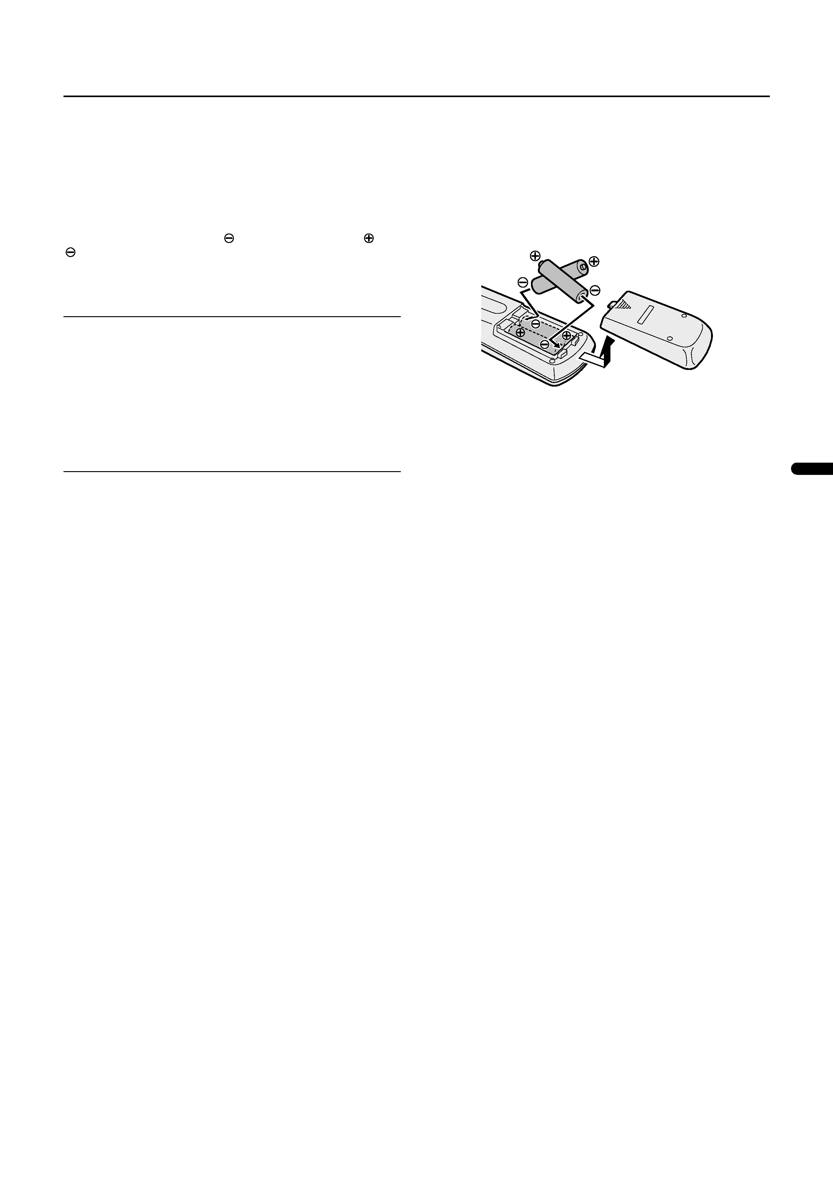
Use two AA/R6 dry cell batteries.
Insert the batteries from the
end, making sure the
and
polarities are correct.
To open the battery compartment, slide the door downwards
and lift off. Replace the door by sliding it upwards until it is se-
cure.
Note:
· Follow the warnings printed on the batteries.
· Battery life is about six months to one year, depending on
your frequency of use.
· If the remote control does not work properly, replace the
batteries.
· The batteries we supply are only for setting up and test-
ing your TV, please replace them as soon as necessary.
· Always use good quality batteries.
s
s
s
s
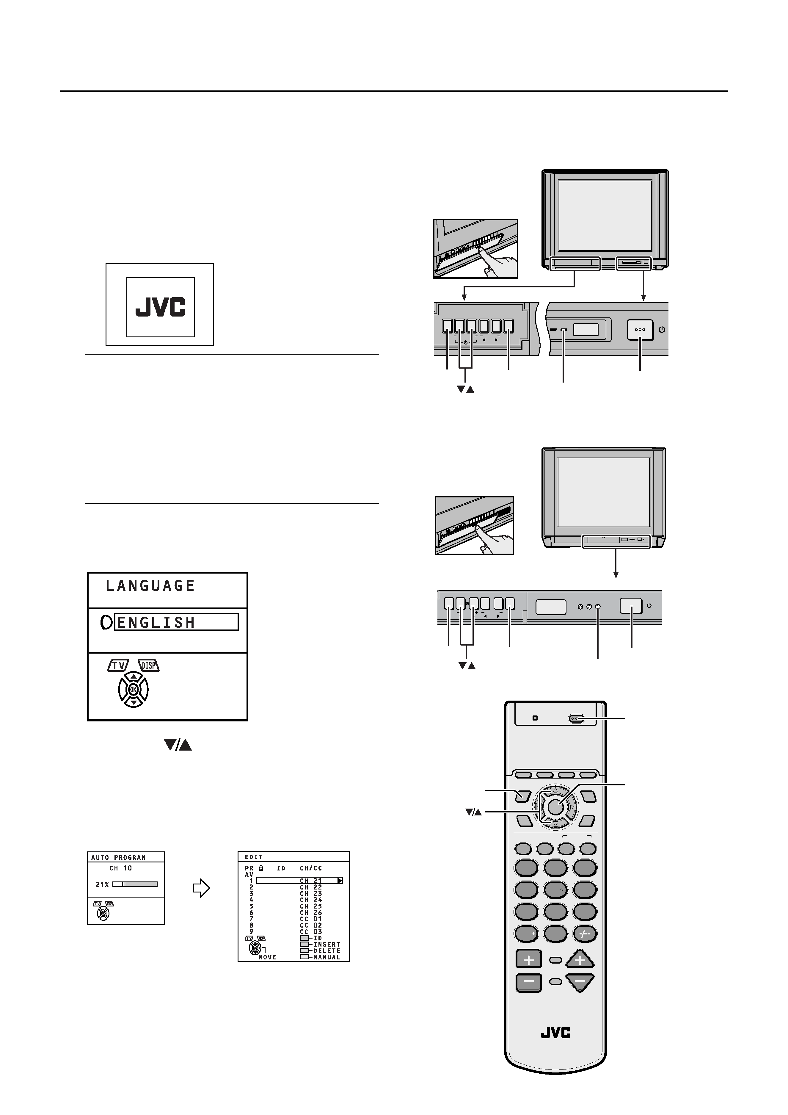
When the TV is first turned on, it enters the initial setting
mode, and the JVC logo is displayed. Follow the instructions
on the on-screen display to make the initial settings.
1 Press the Main power button on the TV.
The Power lamp lights red (for power on), then green (for
TV on) and the JVC logo is displayed.
Note:
· If the power lamp stays red and does not change to
green:
Your TV is in the standby mode. Press the POWER
button on the remote control to turn your TV on.
· The JVC logo does not appear when your TV has
been turned on once.
In this case, use the LANGUAGE and AUTO PRO-
GRAM functions to make the initial settings. For de-
tails, see INSTALL on page 23.
2 Press the OK button.
The LANGUAGE menu appears.
3 Press the
buttons to choose ENG-
LISH. Then press the OK button. The
AUTO PROGRAM function starts.
The AUTO PROGRAM menu appears and received TV
channels are automatically registered in the Programme
numbers (PR).
To cancel the AUTO PROGRAM function:
Press the TV/VIDEO button.
BBE POWER
MENU
OK
CHANNEL
VOLUME
TV/VIDEO
EXIT
/
OK
TV/VIDEO
MENU
TV/VIDEO
DISPLAY
SPATIALIZER
OK
RETURN
AAC
2
13
5
46
8
79
0
SYSTEM
POWER
COLOUR
CHANNEL
CHANNEL
VOLUME
SCAN
MUTING
SOUND
ZOOM
RM-C114
TV
VNR
AUTO
POWER
OK
TV/VIDEO
TV/VIDEO
VOLUME
CHANNEL
EXIT
OK
MENU
ECO
TIMER
POWER
ON
/
OK
TV/VIDEO
Main power button
POWER lamp
<AV-29R9B / AV-29R9>
<AV-25P9>
Main power button
POWER lamp

4 After the TV channels have been regis-
tered in the Programme numbers (PR),
the EDIT menu appears.
You can proceed to edit the Programme numbers (PR)
using the EDIT/MANUAL function. For details, see "ED-
IT/MANUAL" on page 24.
When not using the EDIT/MANUAL function:
If you do not need to use the EDIT/MANUAL function,
go to the next step.
5 Now, the initial settings are complete,
and you can watch the TV.
Note:
· If a TV channel you want to view is not set to a Pro-
gramme number (PR), manually set it using the
MANUAL function. For details, see EDIT/MANUAL
on page 24.
· The TV channel is not registered in Programme
number PR 0 (AV). When you want to register a TV
channel to PR 0 (AV), manually set it using the MAN-
UAL function. For details, see EDIT/MANUAL on
page 24.