SERVICE MANUAL
AV-21L31
AV-25L31
COLOR TELEVISION
BASIC CHASSIS
CH
No. 51969
Jun. 2002
COPYRIGHT © 2002 VICTOR COMPANY OF JAPAN, LTD.
RM-C248 REMOTE CONTROL UNIT
DISPLAY
MENU
POWER
CHANNEL
VOLUME
OFF TIMER
TV/VIDEO
PICTURE MODE
CHANNEL SCAN
ECO SENSOR
MUTING
RETURN
123
456
78
0
9
CLOSED
CAPTION
100
AV-21L31/AR
AV-25L31/AR
RM-C248-2C
CONTENTS
a SPECIFICATIONS ....................................................................................................................................2
a OPERATING INSTRUCTIONS (APPENDIX)
a SAFETY PRECAUTIONS .........................................................................................................................3
a FEATURES ..............................................................................................................................................4
a FUNCTIONS .............................................................................................................................................5
a SPECIFIC SERVICE INSTRUCTIONS ....................................................................................................6
a SERVICE ADJUSTMENTS ....................................................................................................................12
a STANDARD CIRCUIT DIAGRAM (APPENDIX) .................................................................................. 2-1
a PARTS LIST ...........................................................................................................................................31
2No. 51969
AV-21L31
AV-25L31
Dimensions (W × H × D)
59.8cm × 46.8cm × 47.2cm
68.2cm × 53.8cm × 47.8cm
Mass
22kg
30kg
TV RF System
CCIR(M)
Color System
TV Mode
NTSC3.58, PAL-M, PAL-N
VIDEO Mode
NTSC3.58, PAL-M, PAL-N
Stereo System
BTSC (Multi channel Sound)
Receiving Frequency
VHF (VL)
55.25MHz 83.25MHz (02 06)
VHF (VH)
175.25MHz 211.25MHz (07 13)
UHF
471.25MHz 801.25MHz (14 69)
CATV
Low Band
(02 06, A-8) by (02 06 & 01)
--
High Band
(07 13) by (07 13)
Mid Band
(A I) by (14 22)
Super Band
(J W) by (23 36)
(55.25MHz 799.25MHz)
Hyper Band
(W+1 W+28) by (37 64)
Ultra Band
(W+29 W+84) by (65 125)
Sub Mid Band
(A8, A7 A1) by (01, 93 99)
--
TV/CATV Total Channel
181 Channel
Intermediate
VIF Carrier
45.75MHz
Frequency
SIF Carrier
41.25MHz (4.5MHz)
Color Sub Carrier Frequency
NTSC (3.58MHz), PAL-M (3.57MHz), PAL-N (3.58MHz)
Aerial Input Terminal
75Ø Unbalanced
Power Input
AC110 240V, 50 / 60Hz
Power Consumption
115W (Max.) / 75W (Avg.)
150W(Max.) / 90W(Avg.)
Picture Tube
Visible size : 51cm measured diagonally
Visible side : 61cm measured
diagonally
High Voltage
29kV ± 1.5kV (at cut-off in service mode)
31kV ± 1.5kV
(at cut-off in service mode)
Speaker
5 × 12cm
Oval type ×2
Audio Output
5W ×2
Video / Audio Input (1 / 2 / 3)
Video(1,3)
: 1Vp-p, 75Ø (RCA pin jack)
Audio(1,2,3) : 500mVrms ( -4dBs ), High Impedance (RCA pin jack)
Component Input ( Input 2 )
Y: 1Vp-p positive (negative sync provided, when terminated with 75Ø)
CB/CR
: 0.7Vp-p 75Ø
Video/Audio Output
1Vp-p, 75Ø (RCA pin jack)
500mVrms(-4dBs)
Low impedance (1000Hz when modulated 100%) (RCA pin jack)
Headphone Jack
Stereo mini jack (3.5)
Remote Control Unit
RM-C248-2C
(Battery size: AA/R06/UM-3 × 2)
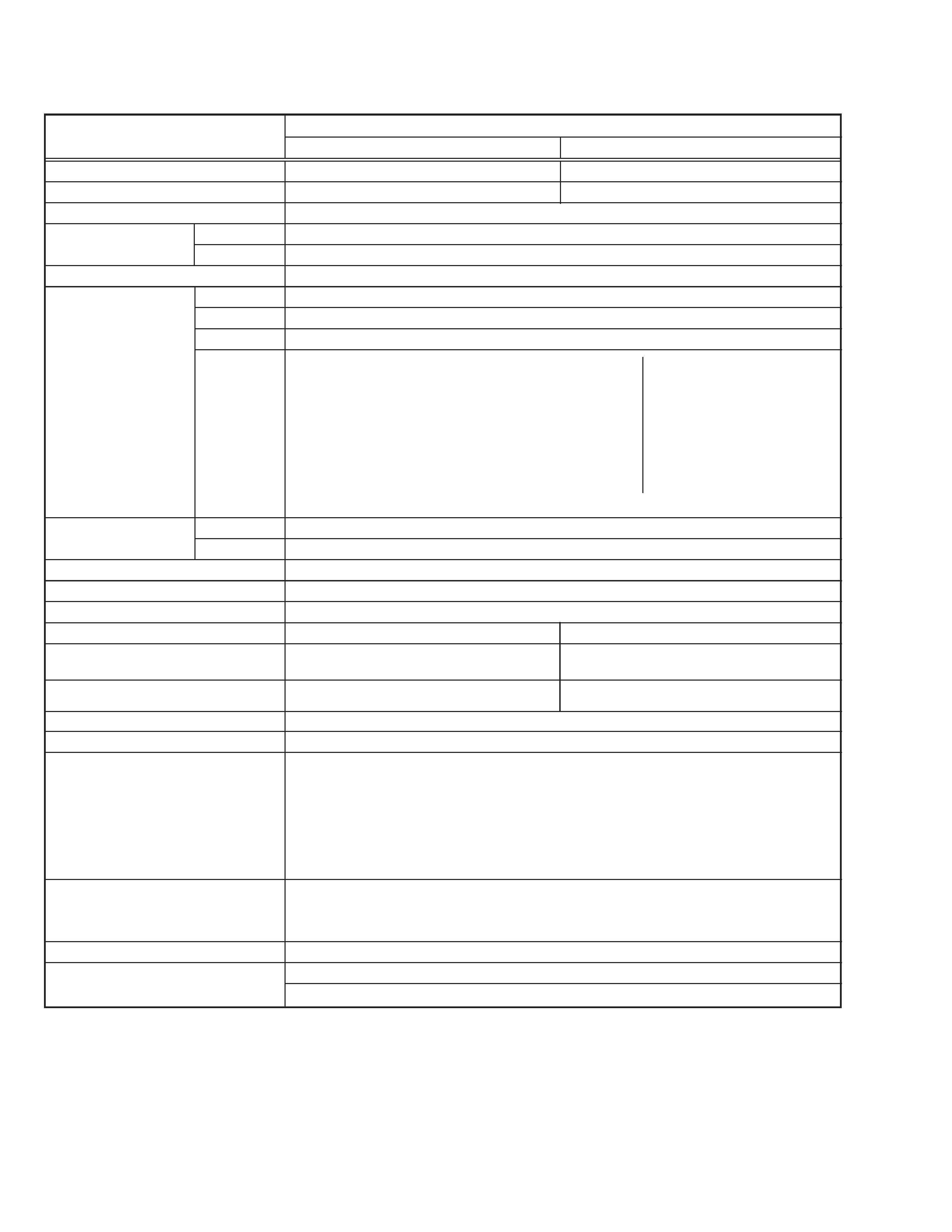
SPECIFICATIONS
Design & specifications are subject to change without notice.
Items
Contents
AV-21L31/AR
AV-25L31/AR
No. 51969
3
AV-21L31
AV-25L31
SAFETY PRECAUTIONS
1. The design of this product contains special hardware, many circuits
and components specially for safety purposes. For continued pro-
tection, no changes should be made to the original design unless
authorized in writing by the manufacturer. Replacement parts must
be identical to those used in the original circuits. Service should be
performed by qualified personnel only.
2. Alterations of the design or circuitry of the products should not be
made. Any design alterations or additions will void the manufactur-
er's warranty and will further relieve the manufacturer of responsi-
bility for personal injury or property damage resulting therefrom.
3. Many electrical and mechanical parts in the products have special
safety-related characteristics. These characteristics are often not
evident from visual inspection nor can the protection afforded by
them necessarily be obtained by using replacement components
rated for higher voltage, wattage, etc. Replacement parts which have
these special safety characteristics are identified in the parts list of
Service manual. Electrical components having such features are
identified by shading on the schematics and by (
!) on the parts
list in Service manual. The use of a substitute replacement which
does not have the same safety characteristics as the recommended
replacement part shown in the parts list of Service manual may
cause shock, fire, or other hazards.
4. Don't short between the LIVE side ground and ISOLATED (NEU-
TRAL) side ground or EARTH side ground when repairing.
Some model's power circuit is partly different in the GND. The differ-
ence of the GND is shown by the LIVE : (
) side GND, the ISO-
LATED (NEUTRAL) : (
) side GND and EARTH : (
) side GND.
Don't short between the LIVE side GND and ISOLATED (NEUTRAL)
side GND or EARTH side GND and never measure the LIVE side
GND and ISOLATED (NEUTRAL) side GND or EARTH side GND
at the same time with a measuring apparatus (oscilloscope etc.).
If above note will not be kept, a fuse or any parts will be broken.
5. If any repair has been made to the chassis, it is recommended that
the B1 setting should be checked or adjusted (See ADJUSTMENT
OF B1 POWER SUPPLY).
6. The high voltage applied to the picture tube must conform with that
specified in Service manual. Excessive high voltage can cause an
increase in X-Ray emission, arcing and possible component dam-
age, therefore operation under excessive high voltage conditions
should be kept to a minimum, or should be prevented. If severe
arcing occurs, remove the AC power immediately and determine
the cause by visual inspection (incorrect installation, cracked or
melted high voltage harness, poor soldering, etc.). To maintain the
proper minimum level of soft X-Ray emission, components in the
high voltage circuitry including the picture tube must be the exact
replacements or alternatives approved by the manufacturer of the
complete product.
7. Do not check high voltage by drawing an arc. Use a high voltage
meter or a high voltage probe with a VTVM. Discharge the picture
tube before attempting meter connection, by connecting a clip lead
to the ground frame and connecting the other end of the lead through
a 10kØ 2W resistor to the anode button.
8. When service is required, observe the original lead dress. Extra
precaution should be given to assure correct lead dress in the high
voltage circuit area. Where a short circuit has occurred, those com-
ponents that indicate evidence of overheating should be replaced.
Always use the manufacturer's replacement components.
9. Isolation Check
(Safety for Electrical Shock Hazard)
After re-assembling the product, always perform an isolation check
on the exposed metal parts of the cabinet (antenna terminals, video/
audio input and output terminals, Control knobs, metal cabinet, screw
heads, earphone jack, control shafts, etc.) to be sure the product is
safe to operate without danger of electrical shock.
(1) Dielectric Strength Test
The isolation between the AC primary circuit and all metal parts
exposed to the user, particularly any exposed metal part having a
return path to the chassis should withstand a voltage of 3000V AC
(r.m.s.) for a period of one second.
(. . . . Withstand a voltage of 1100V AC (r.m.s.) to an appliance rated
up to 120V, and 3000V AC (r.m.s.) to an appliance rated 200V or
more, for a period of one second.)
This method of test requires a test equipment not generally found in
the service trade.
(2) Leakage Current Check
Plug the AC line cord directly into the AC outlet (do not use a line
isolation transformer during this check.). Using a "Leakage Current
Tester", measure the leakage current from each exposed metal part
of the cabinet, particularly any exposed metal part having a return
path to the chassis, to a known good earth ground (water pipe, etc.).
Any leakage current must not exceed 0.5mA AC (r.m.s.).
However, in tropical area, this must not exceed 0.2mA AC (r.m.s.).
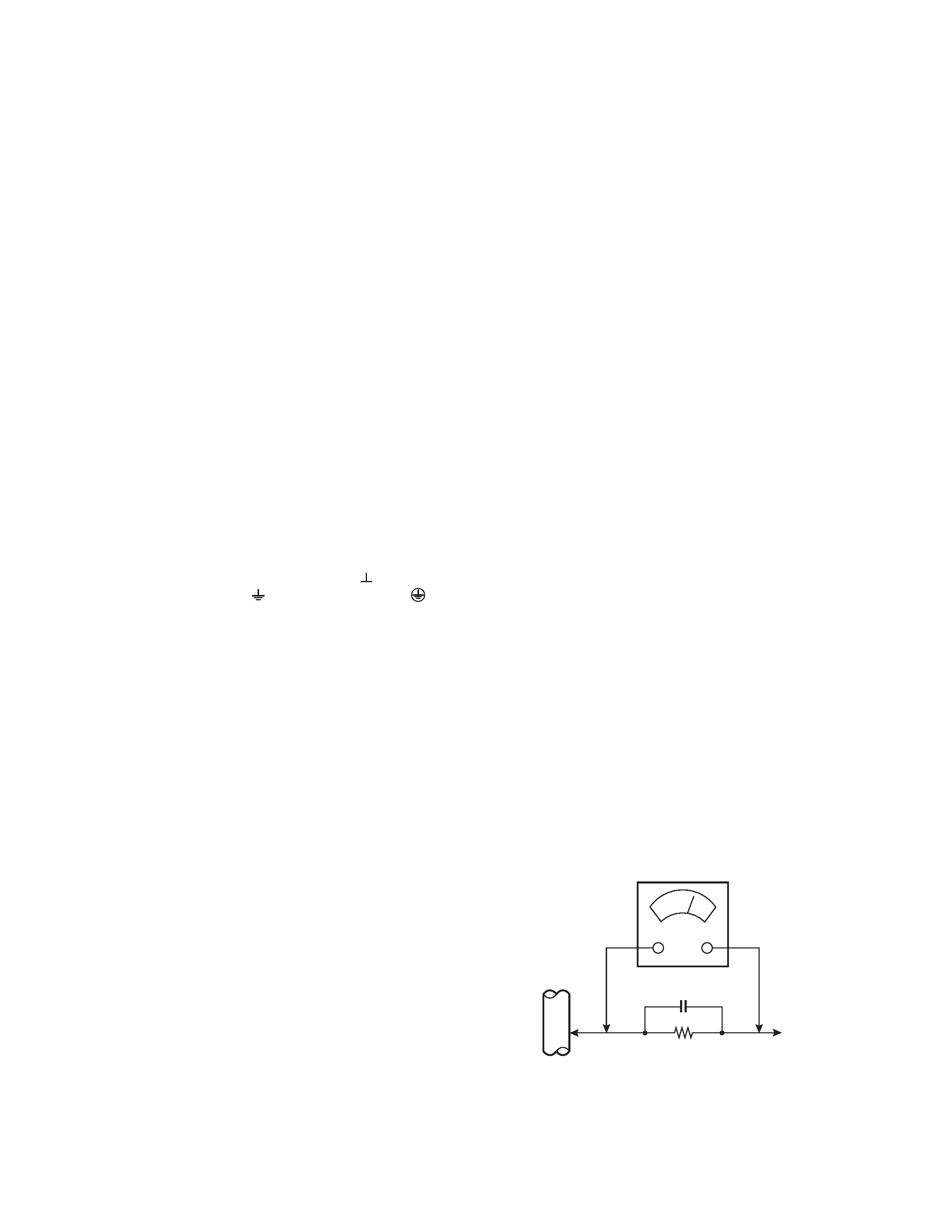
Alternate Check Method
Plug the AC line cord directly into the AC outlet (do not use a line
isolation transformer during this check.). Use an AC voltmeter hav-
ing 1000 ohms per volt or more sensitivity in the following manner.
Connect a 1500Ø 10W resistor paralleled by a 0.15µF AC-type ca-
pacitor between an exposed metal part and a known good earth
ground (water pipe, etc.). Measure the AC voltage across the resis-
tor with the AC voltmeter. Move the resistor connection to each ex-
posed metal part, particularly any exposed metal part having a re-
turn path to the chassis, and measure the AC voltage across the
resistor. Now, reverse the plug in the AC outlet and repeat each
measurement. Any voltage measured must not exceed 0.75V AC
(r.m.s.). This corresponds to 0.5mA AC (r.m.s.).
However, in tropical area, this must not exceed 0.3V AC (r.m.s.).
This corresponds to 0.2mA AC (r.m.s.).
AC VOLTMETER
(HAVING 1000/V,
OR MORE SENSITIVITY)
PLACE THIS PROBE
ON EACH EXPOSED
METAL PART
1500 10W
0.15µF AC-TYPE
GOOD EARTH GROUND
4No. 51969
AV-21L31
AV-25L31
FEATURES
s New chassis design enables use of an interactive on-screen control.
s Pure flat CRT produces fine textured picture in every detail.
s Wide range voltage (110V ~ 220V) for AC power input.
s With AUDIO/VIDEO/COMPONENT input terminals.
s I 2 C bus control utilizes single chip ICs.
s By means of AUTO PROGRAM, the TV stations can be selected
automatically and the TV channels can also be rearranged auto-
matically.
s Built-in DIGITAL ECO MODE (ECONOMY, ECOLOGY).
In accordance with the brightness in a room, the brightness and/or
contrast of the picture can be adjusted automatically to make the
optimum picture which is easy on the eye.
s Built-in OFF TIMER & RETURN +.
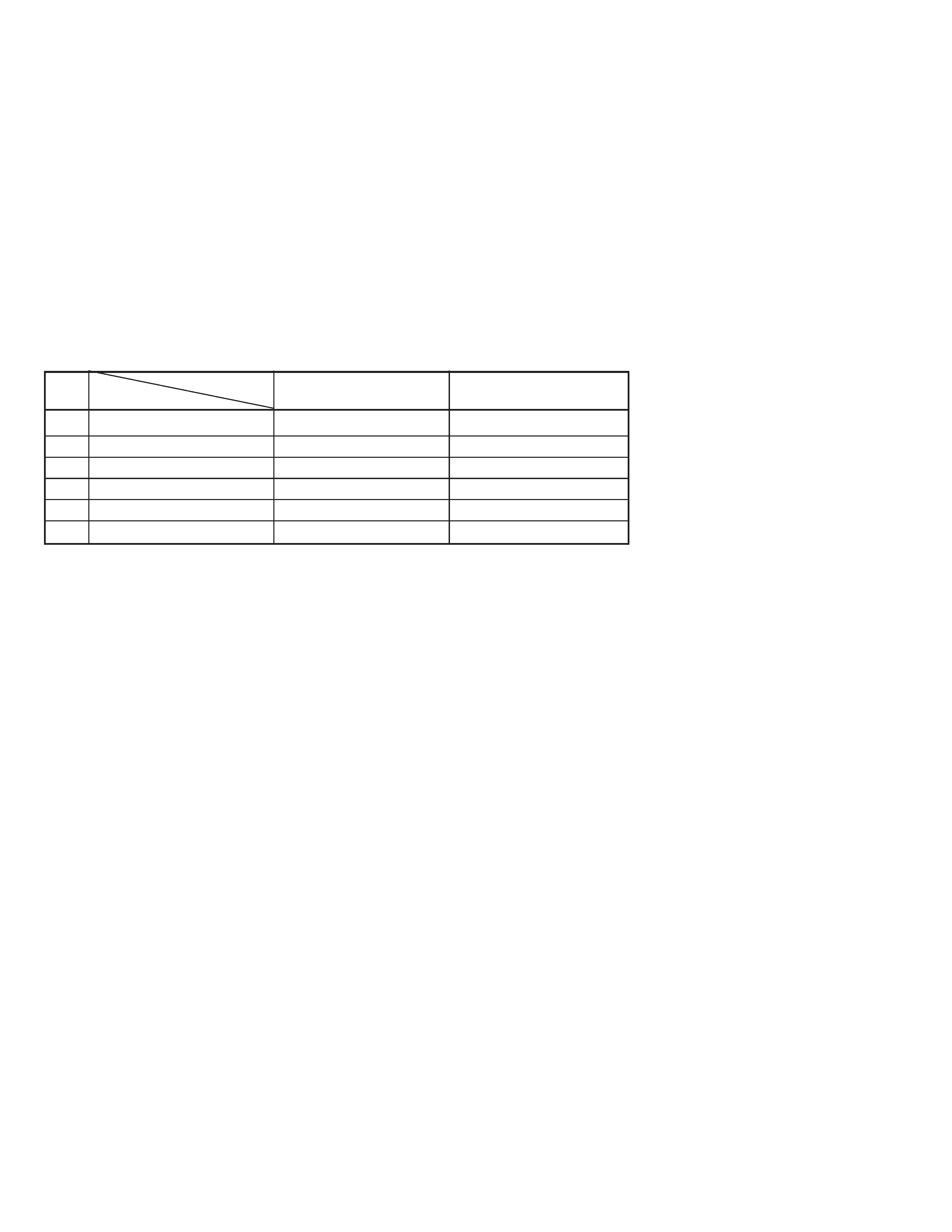
MAIN DIFFERENCE LIST
!
MODEL No.
AV-21L31/AR
AV-25L31/AR
Part Name
!
MAIN PWB ASS'Y
SCH-1503A-R2
SCH-1504A-R2
!
PICTURE TUBE
A51QDX992X002
A59QDF891X002/S
!
DEG COIL
QQW0118-001
QQW0119-001
!
FBT
QQH0104-001
QQH0097-001
FRONT CABINET
GG10129-020A-HK
GG10133-016A-HK
!
REAR COVER
GG10130-008A-HK
GG10134-004A-HK
No. 51969
5
AV-21L31
AV-25L31
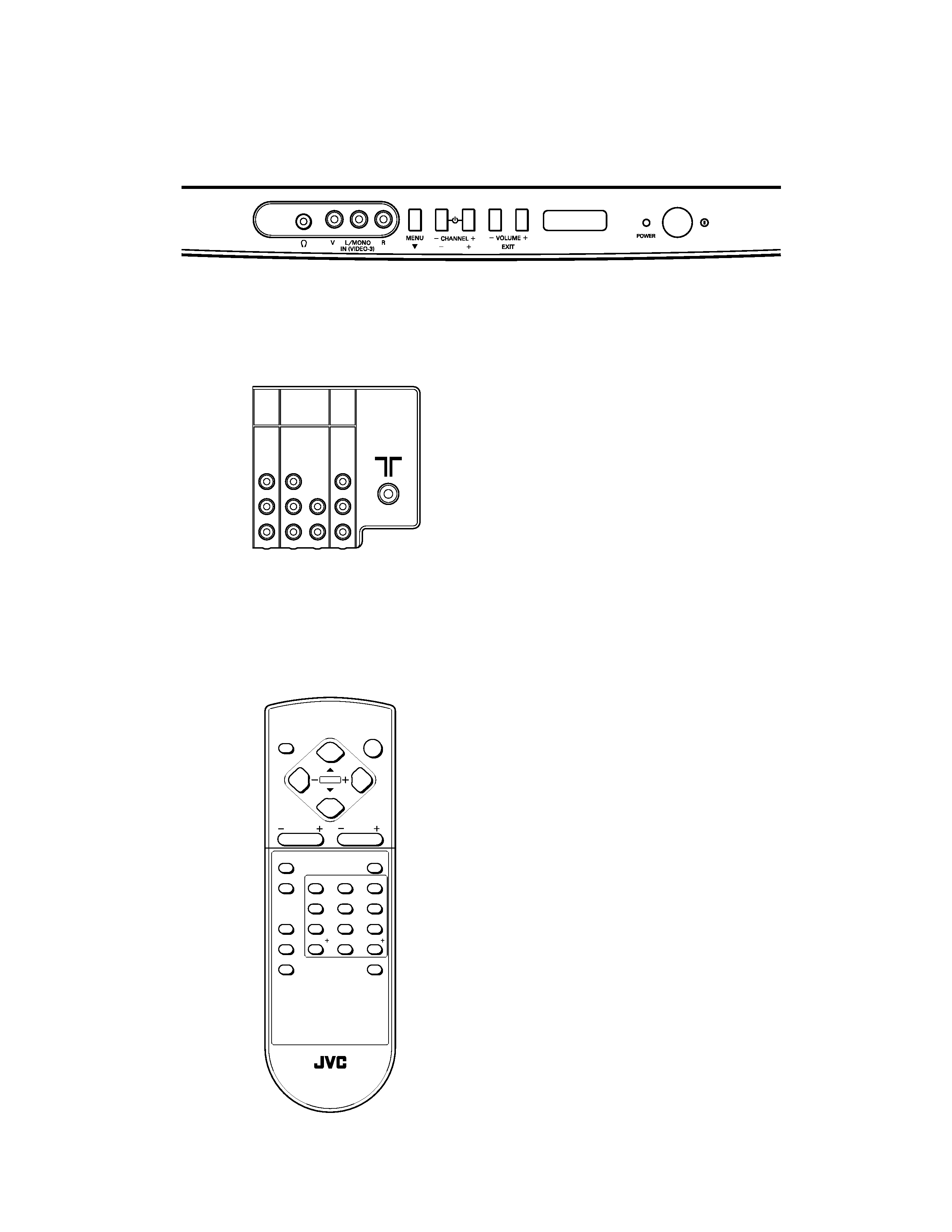
FUNCTIONS
a REAR PANEL
a FRONT PANEL
a REMOTE CONTROL UNIT
RM-C248-2C
RM-C248 REMOTE CONTROL UNIT
DISPLAY
MENU
POWER
CHANNEL
VOLUME
OFF TIMER
TV/VIDEO
PICTURE MODE
CHANNEL SCAN
ECO SENSOR
MUTING
RETURN
123
456
78
0
9
CLOSED
CAPTION
100
VIDEO-1
INPUT
OUTPUT
COMPONENT
(VIDEO-2)
INPUT
V
MONO
L/
V
Y/
V
L
MONO
L/
CB
R
RR
CR