No. 56039
1
AV-21PX
CONTENTS
s SPECIFICATIONS ........................................................................................................................... 2
s SAFETY PRECAUTIONS ................................................................................................................ 3
s FEATURES ...................................................................................................................................... 4
5 OPERATING INSTRUCTIONS (APPENDED) .............................................................................. 1-1
s SPECIFIC SERVICE INSTRUCTIONS ............................................................................................ 4
s SERVICE ADJUSTMENTS ............................................................................................................10
5 STANDARD CIRCUIT DIAGRAM (APPENDED) ......................................................................... 2-1
s PARTS LIST ................................................................................................................................... 29
BASIC CHASSIS
CM-F
COPYRIGHT
© 2000 VICTOR COMPANY OF JAPAN, LTD.
No. 56039
Jul. 2000
+
+
-
-
AV-21PX
SERVICE MANUAL
COLOUR TELEVISION
AV-21PX
AV-21PX
No. 56039
2
SPECIFICATIONS
Item
Content
Dimensions (W
× H × D)
596mm
× 468.5mm × 481.5mm
Mass
25kg
TV RF System
B / G, I, D / K, K1, M
Colour System
TV Mode
PAL / SECAM / NTSC3.58 / NTSC4.43
VIDEO Mode
PAL / SECAM / NTSC3.58 / NTSC4.43
Receiving Frequency
VHF (VL)
46.25MHz ~ 168.25MHz
VHF (VH)
175.25MHz ~ 463.25MHz
UHF
471.25MHz ~ 863.25MHz
CATV
q Cable TVs of Mid (X-Z, S1-S10)
Super (S11-S20) & Hyper (S21-S41) bands receivable
Intermediate
VIF Carrier
38.0MHz
Frequency
31.5MHz (6.5MHz)
SIF Carrier
32.0MHz (6.0MHz)
32.5MHz (5.5MHz)
33.5MHz (4.5MHz)
Colour Sub Carrier Frequency
PAL (4.43MHz), SECAM (4.40625MHz / 4.25MHz)
NTSC (3.58MHz / 4.43MHz)
Aerial Input Terminal
75
Unbalanced
Power Input
AC110 ~ 240V, 50/60Hz
Power Consumption
135W (Max.) / 89W (Avg.)
Picture Tube
Visible size : 51cm measured diagonally
High Voltage
29kV
+1/-1.5kV (at zero beam current)
Speaker
5
× 12cm Oval type × 2
Audio Output
5W + 5W
Input (S/Video-1,
Video
1Vp-p, 75
Video-2 & -3, Audio)
S/Video
Y: 1Vp-p Positive (negative sync provided, when terminated with 75
)
C: 0.286Vp-p (burst signal, when terminated with 75
)
Audio (L/R)
500mVrms (
-4dBs), High impedance
Output
Video
1Vp-p, 75
Audio (L/R)
500mVrms (4dBs), Low impedance
Headphone Jack
Stereo mini jack (3.5ø)
Remote Control Unit
RM-C235-1C
(Battery size : AA/R06/UM-3
× 2)
Design & specifications are subject to change without notice.
No. 56039
3
AV-21PX
SAFETY PRECAUTIONS
8.
When service is required, observe the original lead dress. Ex-
tra precaution should be given to assure correct lead dress in
the high voltage circuit area. Where a short circuit has occurred,
those components that indicate evidence of overheating should
be replaced. Always use the manufacturer's replacement com-
ponents.
9.
Isolation Check
(Safety for Electrical Shock Hazard)
After re-assembling the product, always perform an isolation
check on the exposed metal parts of the cabinet (antenna ter-
minals, video/audio input and output terminals, Control knobs,
metal cabinet, screw heads, earphone jack, control shafts, etc.)
to be sure the product is safe to operate without danger of elec-
trical shock.
(1) Dielectric Strength Test
The isolation between the AC primary circuit and all metal parts
exposed to the user, particularly any exposed metal part hav-
ing a return path to the chassis should withstand a voltage of
3000V AC (r.m.s.) for a period of one second.
(. . . . Withstand a voltage of 1100V AC (r.m.s.) to an appliance
rated up to 120V, and 3000V AC (r.m.s.) to an appliance rated
200V or more, for a period of one second.)
This method of test requires a test equipment not generally
found in the service trade.
(2) Leakage Current Check
Plug the AC line cord directly into the AC outlet (do not use a
line isolation transformer during this check.). Using a "Leakage
Current Tester", measure the leakage current from each ex-
posed metal part of the cabinet, particularly any exposed metal
part having a return path to the chassis, to a known good earth
ground (water pipe, etc.). Any leakage current must not exceed
0.5mA AC (r.m.s.).
However, in tropical area, this must not exceed 0.2mA AC
(r.m.s.).
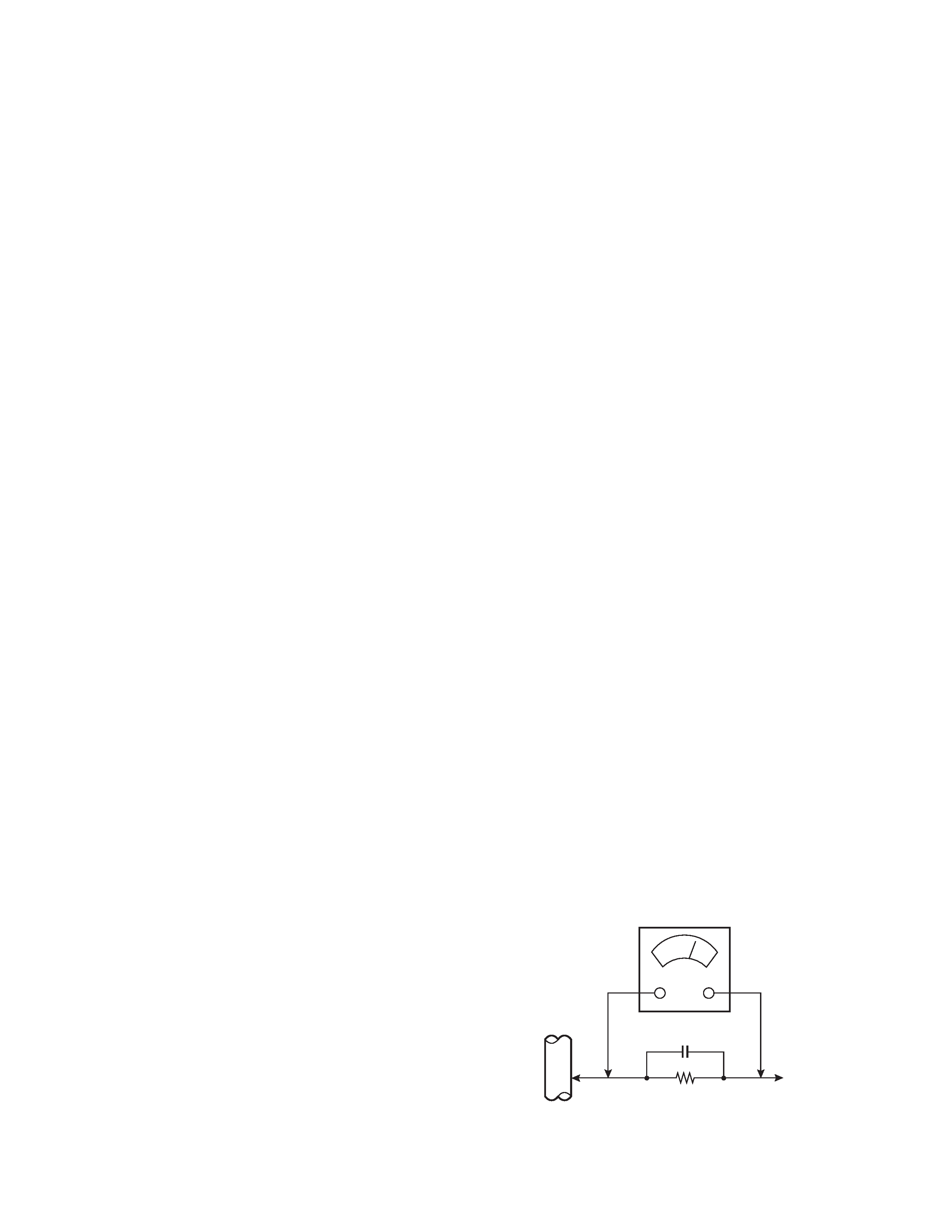
q Alternate Check Method
Plug the AC line cord directly into the AC outlet (do not use a
line isolation transformer during this check.). Use an AC volt-
meter having 1000 ohms per volt or more sensitivity in the fol-
lowing manner. Connect a 1500
10W resistor paralleled by a
0.15
µF AC-type capacitor between an exposed metal part and
a known good earth ground (water pipe, etc.). Measure the AC
voltage across the resistor with the AC voltmeter. Move the
resistor connection to each exposed metal part, particularly any
exposed metal part having a return path to the chassis, and
measure the AC voltage across the resistor. Now, reverse the
plug in the AC outlet and repeat each measurement. Any volt-
age measured must not exceed 0.75V AC (r.m.s.). This corre-
sponds to 0.5mA AC (r.m.s.).
However, in tropical area, this must not exceed 0.3V AC (r.m.s.).
This corresponds to 0.2mA AC (r.m.s.).
1.
The design of this product contains special hardware, many
circuits and components specially for safety purposes. For con-
tinued protection, no changes should be made to the original
design unless authorized in writing by the manufacturer. Re-
placement parts must be identical to those used in the original
circuits. Service should be performed by qualified personnel
only.
2.
Alterations of the design or circuitry of the products should not
be made. Any design alterations or additions will void the
manufacturer's warranty and will further relieve the manufac-
turer of responsibility for personal injury or property damage
resulting therefrom.
3.
Many electrical and mechanical parts in the products have spe-
cial safety-related characteristics. These characteristics are of-
ten not evident from visual inspection nor can the protection
afforded by them necessarily be obtained by using replace-
ment components rated for higher voltage, wattage, etc. Re-
placement parts which have these special safety characteris-
tics are identified in the parts list of Service manual. Electrical
components having such features are identified by shad-
ing on the schematics and by (!) on the parts list in Ser-
vice manual. The use of a substitute replacement which does
not have the same safety characteristics as the recommended
replacement part shown in the parts list of Service manual may
cause shock, fire, or other hazards.
4.
Don't short between the LIVE side ground and ISOLATED
(NEUTRAL) side ground or EARTH side ground when re-
pairing.
Some model's power circuit is partly different in the GND. The
difference of the GND is shown by the LIVE : (#) side GND,
the ISOLATED (NEUTRAL) : (") side GND and EARTH : ($)
side GND. Don't short between the LIVE side GND and ISO-
LATED (NEUTRAL) side GND or EARTH side GND and never
measure with a measuring apparatus (oscilloscope etc.) the
LIVE side GND and ISOLATED (NEUTRAL) side GND or
EARTH side GND at the same time.
If above note will not be kept, a fuse or any parts will be bro-
ken.
5.
If any repair has been made to the chassis, it is recommended
that the B1 setting should be checked or adjusted (See AD-
JUSTMENT OF B1 POWER SUPPLY).
6.
The high voltage applied to the picture tube must conform with
that specified in Service manual. Excessive high voltage can
cause an increase in X-Ray emission, arcing and possible com-
ponent damage, therefore operation under excessive high volt-
age conditions should be kept to a minimum, or should be pre-
vented. If severe arcing occurs, remove the AC power immedi-
ately and determine the cause by visual inspection (incorrect
installation, cracked or melted high voltage harness, poor sol-
dering, etc.). To maintain the proper minimum level of soft X-
Ray emission, components in the high voltage circuitry includ-
ing the picture tube must be the exact replacements or alterna-
tives approved by the manufacturer of the complete product.
7.
Do not check high voltage by drawing an arc. Use a high volt-
age meter or a high voltage probe with a VTVM. Discharge the
picture tube before attempting meter connection, by connect-
ing a clip lead to the ground frame and connecting the other
end of the lead through a 10k
2W resistor to the anode but-
ton.
AC VOLTMETER
(HAVING 1000
/V,
OR MORE SENSITIVITY)
PLACE THIS PROBE
ON EACH EXPOSED
METAL PART
1500
10W
0.15
µF AC-TYPE
GOOD EARTH GROUND
AV-21PX
No. 56039
4
SPECIFIC SERVICE INSTRUCTIONS
DISASSEMBLY PROCEDURE
REMOVING THE REAR COVER
1.
Unplug the AC power cord.
2.
Remove the 12 screws marked "A". (See Fig. 3 on the next
page.)
3.
Withdraw the rear cover backward.
REMOVING THE PB BASE
q
After removing the rear cover.
1.
Slightly raise both sides of the PB Base by hand and remove
the 2 claws under both sides of the PB Base from the front
cabinet. (See Fig. 3.)
2.
Withdraw the PB Base backward.
(If necessary, take off the wire clamp, connectors etc.)
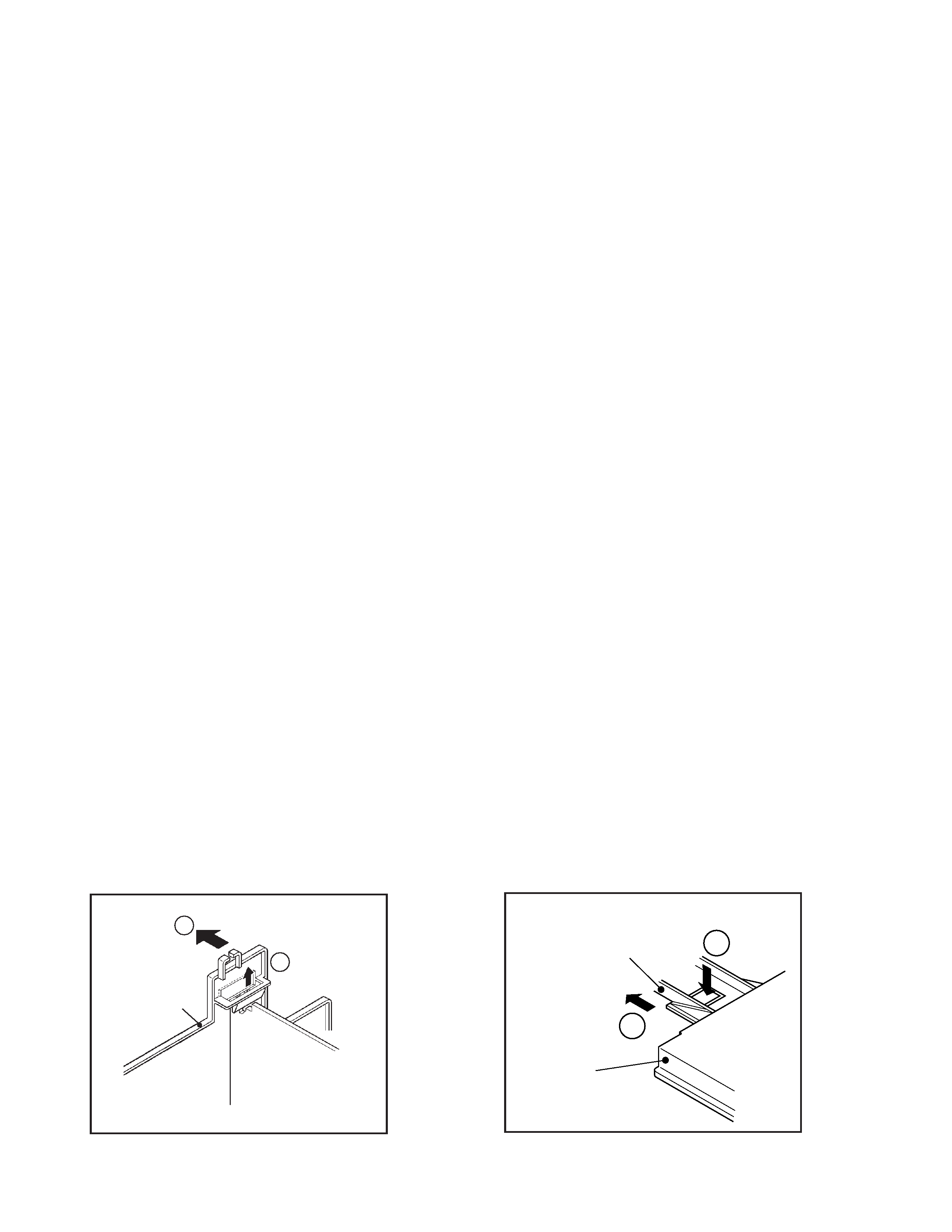
REMOVING THE AV TERMINAL BOARD
q
After removing the rear cover.
1.
Remove the 2 screws marked "B". (See Fig. 3.)
2.
Unhook the claw (marked "C") of the AV Terminal Board from
the PW Board by lifting it upward. (See Fig. 1.)
3.
Then remove the AV Terminal Board backward (in the arrow
direction marked "D"). (See Fig. 1.)
REMOVING THE CONTROL BASE
q
After removing the Rear Cover and the PB Base.
1.
While pushing down the claws marked "E", remove the Control
Base forward (in the arrow direction marked "F"). (See Fig. 2.)
(If necessary, take off the wire clamp, connectors, etc.)
FEATURES
q New chassis design enables use of an interactive on-screen
control.
q Pure flat CRT produces fine textured picture in every detail.
q Wide range voltage for AC power input.
q With AUDIO / VIDEO / S-VIDEO INPUT & OUTPUT terminals.
q MUTING button can reduce the audio level to zero instantly.
q Functional remote control to operate TV set (for channel select,
volume control, power ON/OFF, etc.) from a distance.
q I2C bus control utilizes single chip ICs for IF, V/C (Video/Chroma)
and VSM (Video Status Memory).
q By means of AUTO PROGRAM, the TV stations can be selected
automatically and the TV channels can also be rearranged au-
tomatically.
q Built-in ECO MODE (ECONOMY, ECOLOGY)
In accordance with the brightness in a room, the brightness and/
or contrast of the picture can be adjusted automatically to make
the optimum picture which is easy on the eye.
q Built-in ON TIMER & RETURN +.
q By means of ALC (Auto Level Control), the audio output is auto-
matically controlled at a constant level.
REMOVING THE SPEAKER
q
After removing the rear cover.
1.
Remove the Speaker block by removing the 2 screws marked
"G" . (See Fig. 3.)
2.
Remove the Speaker by removing the 4 screws marked "H".
(See Fig. 3.)
3.
Follow the same steps for removing the other hand speaker.
CHECKING THE MAIN PW BOARD
To check the back side of the Main PW Board, follow the next steps.
1.
Pull out the PB Base. (Refer to "REMOVING THE PB BASE".)
2.
Erect the PB Base vertically so that you can easily check the
back side of the Main PW Board.
CAUTION:
q
When erecting the PB Base, be careful so that there will be no
contacting with other PW Board.
q
Before turning on power, make sure that the CRT earth wire
and other connectors are properly connected.
q
When repairing, connect the Deg. coil to the DEG. connector
on the Main PW Board.
WIRE CLAMPING AND CABLE TYING
1.
Be sure to clamp the wire.
2.
Never remove the cable tie used for tying the wires together.
Should it be inadvertently removed, be sure to tie the wires with
a new cable tie.
Fig. 1
Fig. 2
AV TERMINAL
BOARD
[REAR SIDE]
C
D
CONTROL BASE
[FRONT SIDE]
PB BASE
E
F
No. 56039
5
AV-21PX
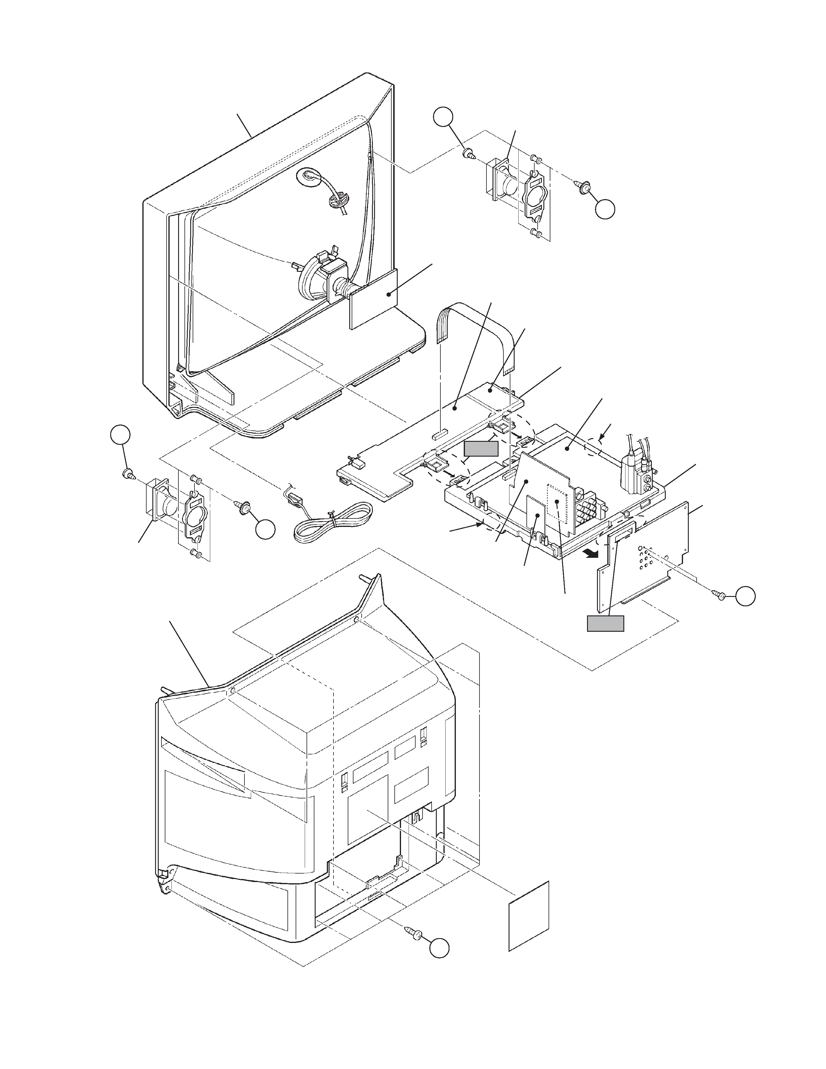
Fig. 3
CRT SOCKET
PWB
FRONT CABINET
FRONT CONTROL PWB
INNER PIN PWB
CONTROL BASE
REAR COVER
CLAW
CLAW
AV TERMINAL
BOARD
SPEAKER
MAIN PWB
PB BASE
B (×2)
Fig. 2
SPEAKER
Fig. 1
G
(
×2)
G
(
×2)
H (×4)
(
×4)
A (×12)
AV SW PWB
IF PWB
ALC PWB
H