No.51998
AV21BJ8ENS
AV21BJ8EPS
AV21BJ8EES
AV20BJ8EES
1
COPYRIGHT © 2002 VICTOR COMPANY OF JAPAN, LTD.
Apr. 2002
AV21BJ8ENS
AV21BJ8EPS
AV21BJ8EES
AV20BJ8EES
CONTENTS
! SPECIFICATIONS
2
!
SAFETY PRECAUTIONS
4
! FEATURES
5
! MAIN DEFERENCE LIST
5
! SPECIFIC SERVICE INSTRUCTIONS
6
!
SERVICE ADJUSTMENTS
11
! PARTS LIST
21
STANDARD CIRCUIT DIAGRAM
2-1
SERVICE MANUAL
COLOUR TELEVISION
AV21BJ8
AV20BJ8
No.51998
AV21BJ8ENS
AV21BJ8EPS
AV21BJ8EES
AV20BJ8EES
2
SPECIFICATIONS
Content
Item
AV21BJ8ENS
AV21BJ8EPS
AV21BJ8EES
AV20BJ8EES
Dimensions ( W×
×
×
×H×
×
×
×D )
596mm× 446mm×490mm
596mm×446mm×490mm
Mass
20kg
17.8kg
TV RF System
B/G (ENS models)
B/G , L/L' (EPS models)
B/G , D/K (EES models)
Colour System
PAL, NTSC3.58 / NTSC4.43(Only EXT mode)----ENS model
PAL , SECAM , NTSC3.58 / NTSC4.43(Only EXT mode)----EPS,EES models
Sound System
Mono
Teletext System
WST (World Standard system)
Receiving Frequency
VHF(VL) 46.25MHz 168.25MHz
(VH) 175.25MHz 463.25MHz
UHF 471.25MHz 863.25MHz
CATV S1-S20&S21-S41&S75-S79 ----- ENS models
S1-S20&S21-S41&S75-S79 ----- EPS models
S1-S20&S21-S41 ------------------- EES models
Intermediate Frequency
VIF Carrier 38.9MHz (B/G , D/K , L) / 33.9MHz (L')
SIF Carrier 33.4MHz (5.5MHz:B/G) / 32.9MHz (6.0MHz:D/K) / 32.4MHz (6.5MHz:L) / 40.4MHz (6.5MHz:L')
Colour Sub Carrier Freq.
PAL 4.43MHz
SECAM 4.25MHz / 4.40625MHz
NT SC 3.58MHz / 4.43MHz
Power Input
AC 220V240V , 50Hz
Power Consumption
85W , 4W(Stand by)
Aerial Input Term
75unbalanc ed, Coaxial
Picture Tube Size
Visible size : 51cm, Meas ured diagonally
Visible size : 48cm, Meas ured diagonally
High Voltage
26kV (in cut-off service mode)
Speaker
5cm×9cm Oval type×2
Au dio Output
8W
REAR TERMINAL(AV1)
21-pin Euro c onnector
FRONT T ERMINAL
Video 1Vp-p 75(RCA pin jack)
Au dio 500mVrms( -4dBs ), High Impedance ( RCA pin jack )
Headphone jack
Mini jac k (3.5mm )
Remote Control Unit
VE-30017763 (RM-C 1100), (AA/R06 dry battery×2)
Design & specifications are subject to change without notice.
No.51998
AV21BJ8ENS
AV21BJ8EPS
AV21BJ8EES
AV20BJ8EES
3
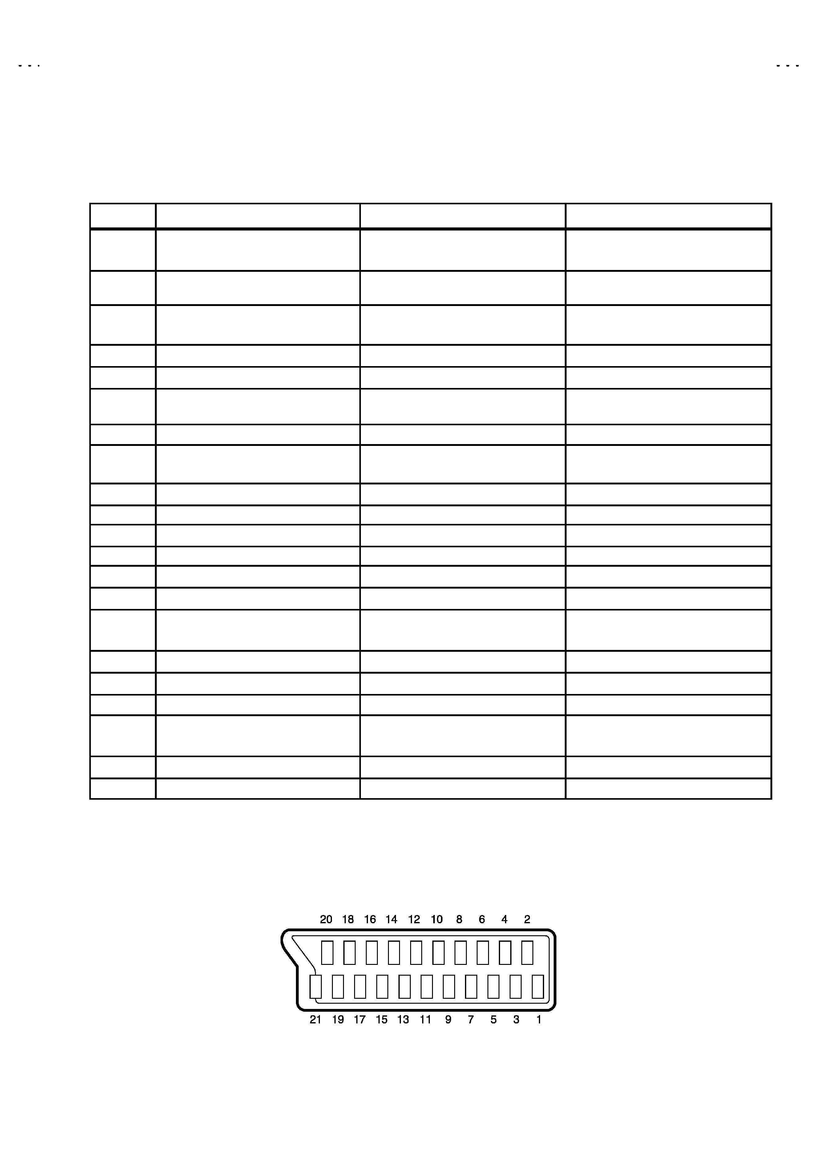
21-pin Euro connector (SCART socket) : AV-1
(P-P= Peak to Peak, S-W= Sync tip to white peak, B-W= Blanking to white peak)
Pin No.
Signal Designation
Matching Value
AV-1
1
AUDIO R output
500mVrms(Nominal),
Low impedanc e
(TV OUT)
2
AUDIO R input
500mVrms(Nominal),
High impedance
3
AUDIO L output
500mVrms(Nominal),
Low impedanc e
(TV OUT)
4
AUDIO GND
5
GND (B)
6
AUDIO L input
500mVrms(Nominal),
High impedance
7
B input
700mVB-W, 75
8
FUNCTON SW
(SLOW SW)
Low : 0-3V, High : 8-12V, High
impedanc e
9
GND (G)
10
SCL3
NC
11
G input
700mV
B-W, 75
12
SDA3
NC
13
GND (R)
14
GND (YS)
15
R / C input
R : 700mVB-W, 75
C : 300mVP-P, 75
(only R)
16
Ys input
Low : 0 - 0.4, High : 1 - 3V, 75
17
GND(VIDEO output)
18
GND(VIDEO input)
19
VIDEO output
1VP-P(Negative going sync ), 75
(TV)
20
VIDEO / Y input
1VP-P(Negative going sync ), 75
21
COMMON GND
[Pin assignment]
No.51998
AV21BJ8ENS
AV21BJ8EPS
AV21BJ8EES
AV20BJ8EES
4
SAFETY PRECAUTIONS
1. The design of this product contains special hardware, many
circuits and components specially for safety purposes. For
continued protection, no changes should be made to the original
design unless authorized in writing by the manufacturer.
Replacement parts must be identic al to thos e used in the original
circuits. Servic e should be performed by qualified personnel
only.
2. Alterations of the design or circuitry of the products should not be
made. Any design alterations or additions will void the
manufacturer's warranty and will further relieve the manufacturer
of responsibility for personal injury or property damage resulting
therefrom.
3. Many electrical and mechanical parts in the products have
special safety-related characteristics. T hese characteristics are
often not evident from visual inspection nor can the protection
afforded by them necessarily be obtained by using replacement
components rated for higher voltage, wattage, etc. Replacement
parts whic h have these special s afety characteristics are
identified in the parts list of Servic e manual. Electrical
components having su ch features are identified by shading
on the schematics and by (!
!
!
!
) on the parts list in Service
manual. The us e of a substitute replacement which does not
have the same safety characteristics as the recommended
replac ement part shown in the parts list of Service manual may
cause shock, fire, or other hazards .
4. Do n't short between the LIVE side ground and ISOL ATED
(NEUTRAL) side ground or EARTH side ground when
repairing.
Some model's power circuit is partly different in the GND. T he
differenc e of the GND is shown by the LIVE : (") side GND, the
ISOLATED(NEUTRAL) : (#) side GND and EARTH : ($) side
GND. Don't short between the LIVE side GND and
ISOLATED(NEUTRAL) side GND or EARTH side GND and
never measure with a measuring apparatus (oscilloscope etc.)
the LIVE side GND and ISOLATED(NEUTRAL) side GND or
EARTH side GND at the s ame time.
If above note will not be kept, a fuse or any parts will be broken.
5. If any repair has been made to the chassis, it is recommended
that the B1 setting should be checked or adjusted (See
ADJUSTMENT OF B1 POWER SUPPLY).
6. The high voltage applied to the picture tube must conform with
that specified in Service manual. Excessive high voltage can
cause an increase in X-Ray emission, arcing and possible
component damage, therefore operation under excessive high
voltage conditions should be k ept to a minimum, or should be
prevented. If s evere arc ing occurs, remove the AC power
immediately and determine the cause by visual inspection
(incorrect installation, cracked or melted high voltage harness,
poor soldering, etc.). To maintain the proper minimum level of
soft X-Ray emission, c omponents in the high voltage circuitry
including the picture tube must be the exact replacements or
alternatives approved by the manufacturer of the c omplete
product.
7. Do not c hec k high voltage by drawing an arc. Use a high voltage
meter or a high v oltage probe with a VTVM. Dis charge the
picture tube before attempting meter connection, by c onnecting
a clip lead to the ground frame and c onnecting the other end of
the lead through a 10k
2W resistor to the anode button.
8. When service is required, observe the original lead dress. Extra
prec aution should be given to assure correct lead dress in the
high voltage circuit area. W here a s hort circuit has occurred,
those components that indicate evidence of overheating should
be replaced. Always use the manufacturer's replacement
components.
9. Isolation Check
(Safety for Electrical Shock Hazard)
After re-ass embling the product, always perform an isolation
check on the exposed metal parts of the cabinet (antenna
terminals, video/audio input and output terminals, Control knobs,
metal cabinet, screwheads, earphone jack , control shafts, etc.)
to be sure the product is s afe to operate without danger of
electrical shoc k.
(1) Dielectric Strength Test
The isolation between the AC primary circuit and all metal parts
exposed to the us er, particularly any expos ed metal part having a
return path to the chass is should withs tand a voltage of 3000V
AC (r.m.s.) for a period of one sec ond.
(. . . . Withstand a voltage of 1100V AC (r.m.s.) to an applianc e
rated up to 120V, and 3000V AC (r.m.s.) to an appliance rated
200V or more, for a period of one second.)
This method of test requires a test equipment not generally found
in the servic e trade.
(2) Leakage Current Check
Plug the AC line c ord directly into the AC outlet (do not use a line
isolation transformer during this check.). Using a " Leakage
Current Tester", measure the leakage current from each exposed
metal part of the cabinet, particularly any expos ed metal part
having a return path to the chassis , to a known good earth
ground (water pipe, etc.). Any leakage current must not exceed
0.5mA AC (r.m.s.).
However, in tropic al area, this must not exceed 0.2mA AC
(r.m.s.).
"
"
"
"
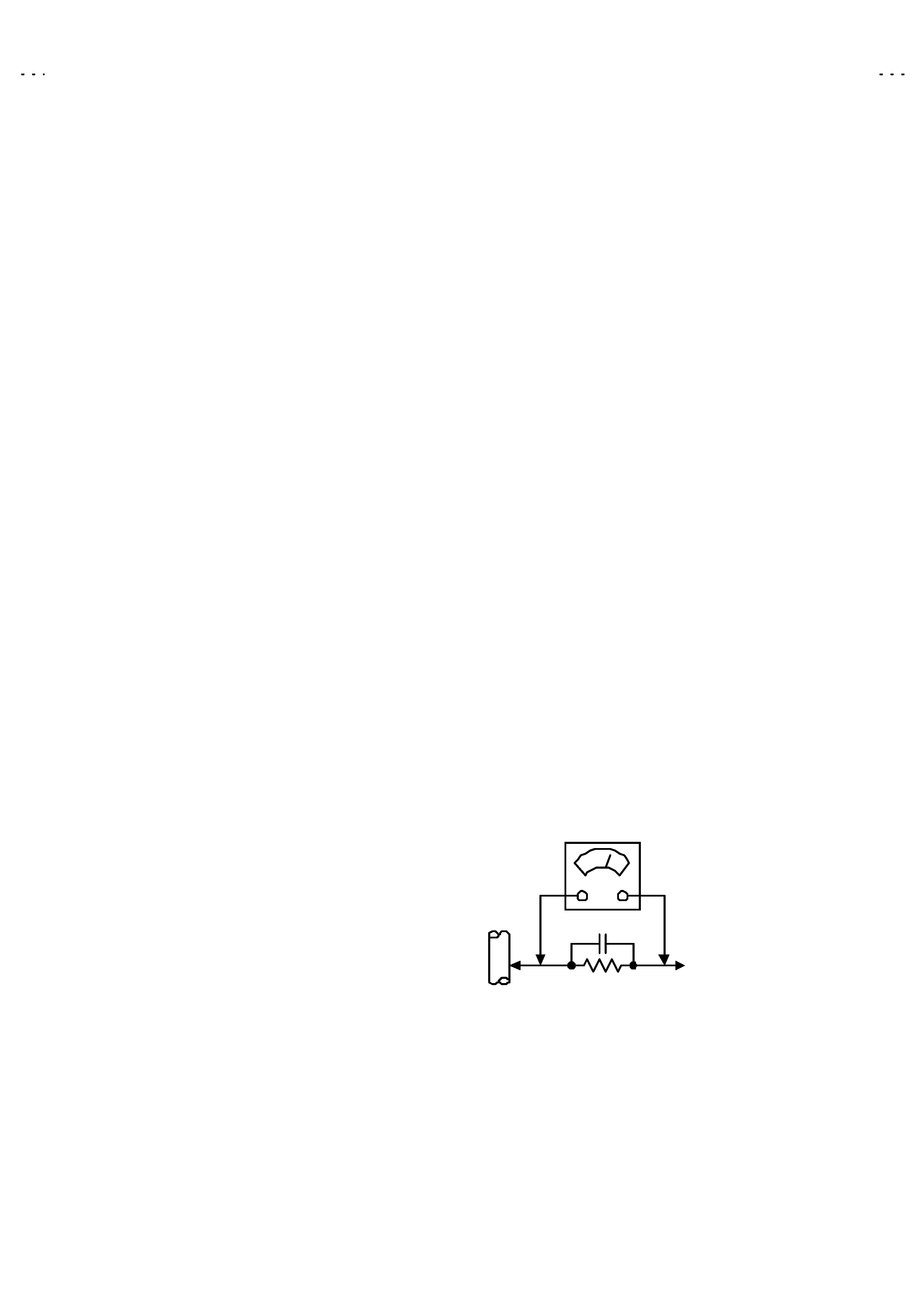
Alternate Check Method
Plug the AC line c ord directly into the AC outlet (do not use a line
isolation transformer during this check.). Use an AC voltmeter
having 1000 ohms per volt or more sens itivity in the following
manner. Connec t a 1500
10W res istor paralleled by a 0.15µF
AC-type c apacitor between an exposed metal part and a known
good earth ground (water pipe, etc.). Meas ure the AC voltage
across the res istor with the AC voltmeter. Move the resistor
connec tion to each exposed metal part, particularly any exposed
metal part having a return path to the chassis, and measure the
AC voltage ac ross the res istor. Now, reverse the plug in the AC
outlet and repeat eac h measurement. Any voltage measured
must not exc eed 0.75V AC (r.m.s.). This c orresponds to 0.5mA
AC (r.m.s.).
However, in tropical area, this must not exceed 0.3V AC ( r.m.s.).
This corresponds to 0.2mA AC (r.m.s.).
0.15F AC-TYPE
1500
10W
GOOD EARTH GROUND
PLACE THIS PROBE
ON EACH EXPOSED
METAL PART
AC VOLTMETER
(HAVING 1000
/V,
OR MOR E SENSITIVITY)
No.51998
AV21BJ8ENS
AV21BJ8EPS
AV21BJ8EES
AV20BJ8EES
5
FEATURES
" This TV set is monaural TV
"
The TELETEXT SYSTEM has a built-in WST system.
" Built-in CHILD LOCK function.
"
Built-in SLEEP TIMER function.
MAIN DIFFERENCE LIST
!
!
!
!
Model Name
Part Name
AV21BJ8ENS
AV21BJ8EPS
AV21BJ8EES
AV20BJ8EES
MAIN PWB
VE-20096167
VE-20096166
VE-20096169
VE-20096170
FRONT AV JACK PWB
VE-20090024
VE-20096663
! PICTURE TUBE (ITC)
VE-30002749
VE-30002748
! DEG COIL
VE-30002124
VE-30002119
! INST BOOK
VE-50026383
VE-50026394
VE20026398