No.51879
AV21BF5ENS
AV21BF5EES
1
COPYRIGHT © 2002 VICTOR COMPANY OF JAPAN, LTD.
Jan. 2002
AV21BF5ENS
AV21BF5EES
CONTENTS
SPECIFICATIONS
2
SAFETY PRECAUTIONS
4
FEATURES
5
MAIN DIFFERENCE LIST
5
SPECIFIC SERVICE INSTRUCTIONS
6
SERVICE ADJUSTMENTS
9
PARTS LIST
17
OPERATING INSTRUCTIONS
STANDARD CIRCUIT DIAGRAM
2-1
SERVICE MANUAL
COLOUR TELEVISION
No.51879
AV21BF5ENS
AV21BF5EES
2
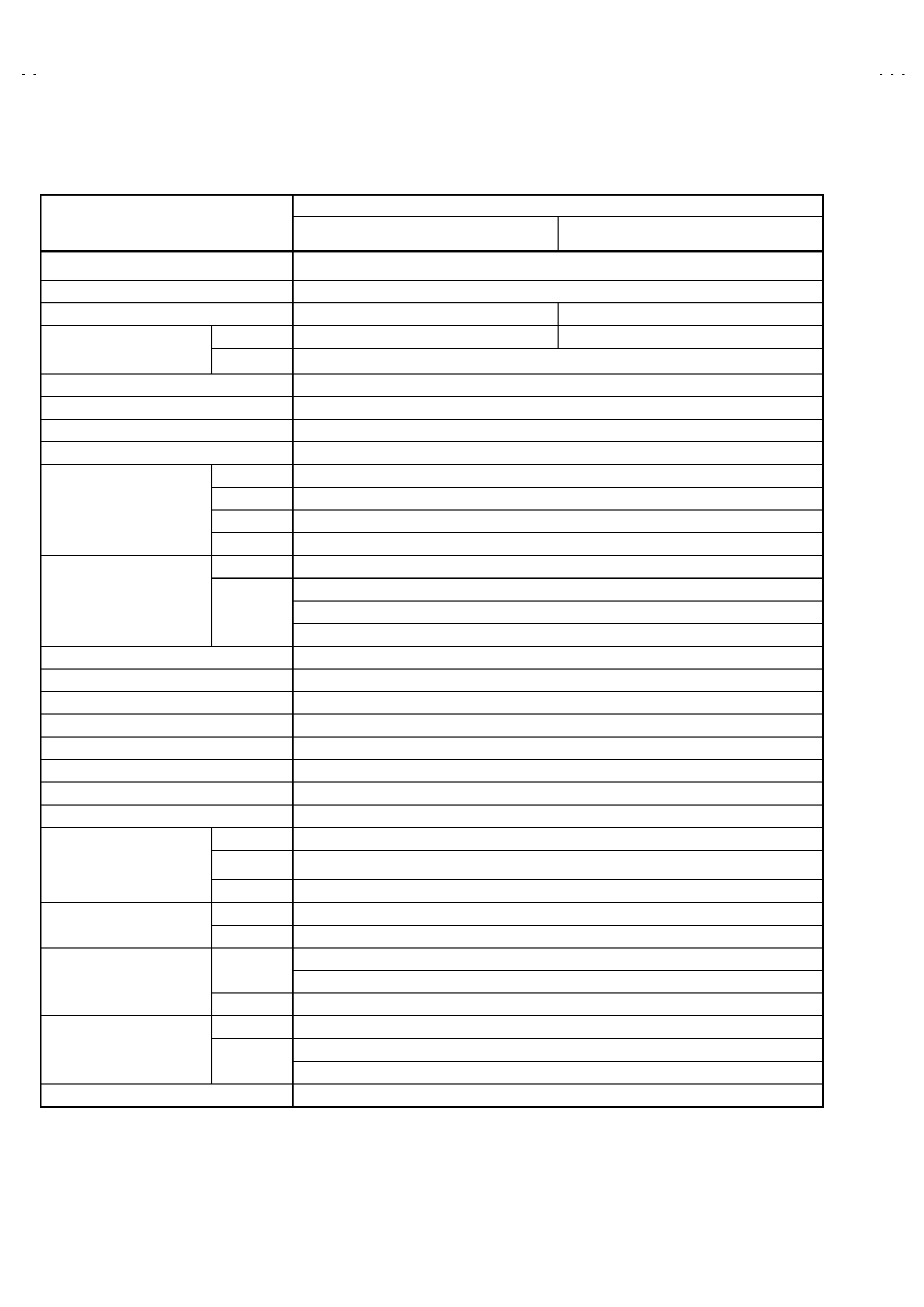
SPECIFICATIONS
Content
ITEM
AV21BF5ENS
AV21BF5EES
Dimensions (WxHxD)
60 x 45 x 48 cm
Weight
22.2 kg
TV RF System
B/G
B/G, D/K, K1
TV Mode
PAL
PAL / SECAM
Colour System
Video Mode
PAL / SECAM / NTSC 3.58 / NTSC 4.43
Teletext System
Fastext / Toptext
Stereo System
A2 / NICAM
Tuning System
Frequency Synthesizer Tuning System
Number Of CH memory position
100 ch
VHF (VL)
46.25MHZ ~ 168.25MHz
VHF (VH)
175.25MHz ~ 463.25MHz
UHF
471.25MHz ~ 863.25MHz
Receiving Frequency
CATV
Super (S11-S20) & Hyper (S21-S41) bands receivable
VIF Carrier
38.9MHz
32.4MHz (6.5MHz)
32.9MHz (6.0MHz)
Intermediate Frequency
SIF Carrier
33.4MHz (5.5MHz)
Colour Sub Carrier Frequency
PAL (4.43MHz), SECAM (4.43MHz), NTSC (3.58MHz/4.43MHz)
Aerial Input Terminal
75 Ohm Unbalanced
Power Input
AC 220 ~ 240V, 50Hz
Power Consumption
95W(Max.)/73W(Avg.) Stand-by<5W
Picture Tube
21 inch measured diagonally
High Voltage
27kV (in cut-off service mode)
Speaker
57x160 mm oval type x2
Audio Output
8W+8W
Video
1Vp-p, 75 Ohm
S/Video
Y: 1Vp-p Positive
C: 0.286Vp-p
Input
Audio (L/R)
500 mVrms, High Impedance
Video
1 Vp-p, 75 Ohm
Output
Audio (L/R)
500 mVrms, Low Impedance
AV1 (Video/Audio/RGB)
Rear Side
AV2 (Video/Audio/S-VHS)
Input Terminal
Front Side
AV3 (Video/Audio)
Front Side
Headphone jack (Stereo mini jack 3.5 )
AV1 (Video/Audio)
Output Terminal
Rear Side
AV2 (Video/Audio) (Selected TV, AV1 or AV3)
Remote Control Unit
RM-C85, Battery size:AAA/R03 x 2
Design & specifications are subject to change without notice.
No.51879
AV21BF5ENS
AV21BF5EES
3
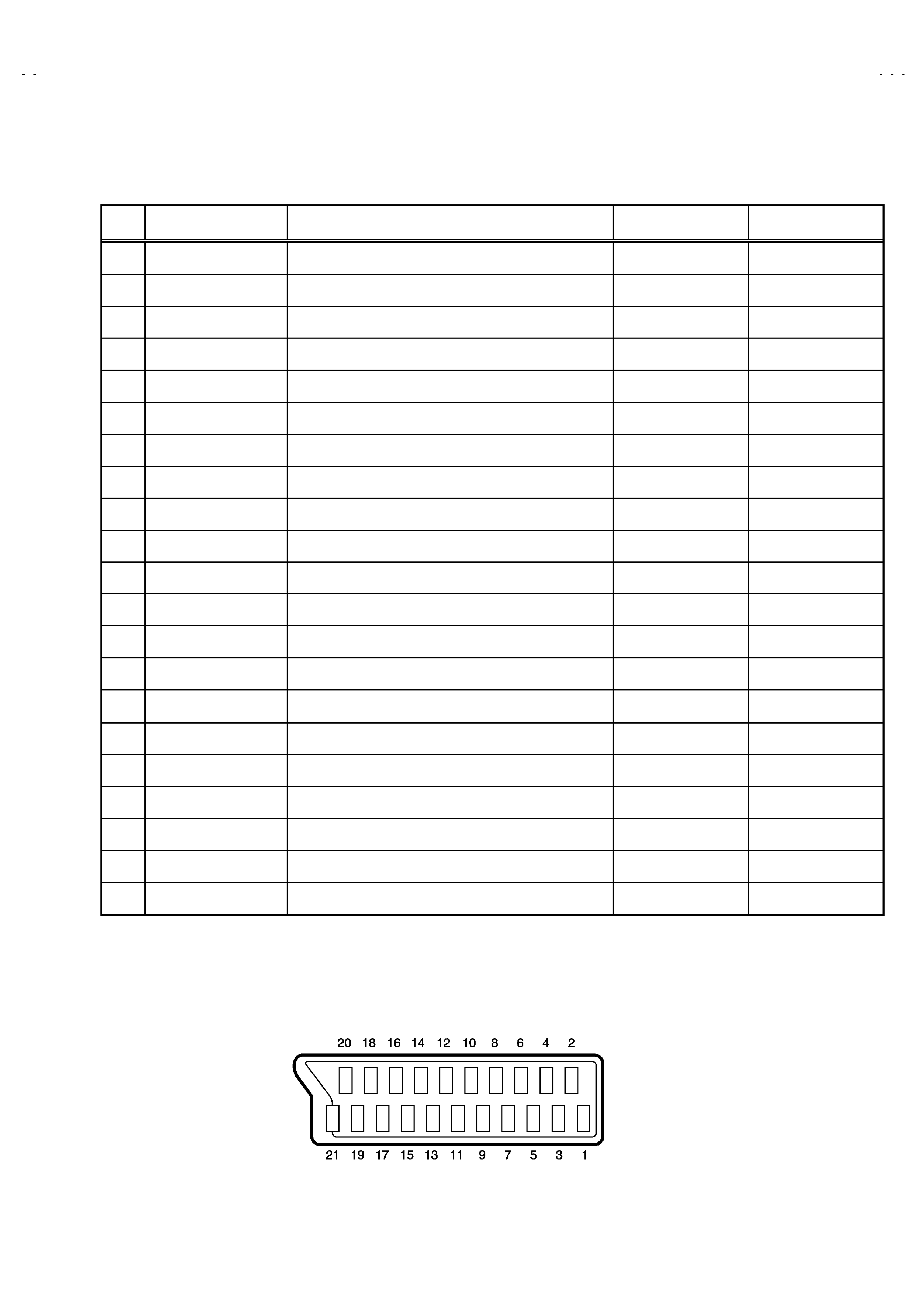
21-pin Euro connector (SCART socket) : AV-1 / AV-2
(P-P= Peak to Peak, S-W= Sync tip to white peak, B-W= Blanking to white peak)
Pin
No.
Signal Designation
Matching Value
AV-1
AV-2
1
AUDIO R output
500mVrms(Nominal),Low impedance
(TV OUT)
(TV/LINE OUT)
2
AUDIO R input
500mVrms(Nominal),High impedance
3
AUDIO L output
500mVrms(Nominal),Low impedance
(TV OUT)
(TV/LINE OUT)
4
AUDIO GND
5
GND (B)
6
AUDIO L input
500mVrms(Nominal), High impedance
7B input
700mVB-W, 75
NC
8
FUNCTON SW
(SLOW SW)
Low : 0-3V, High : 8-12V, High impedance
NC
9
GND (G)
10
-
NC
-
11
G input
700mVB-W, 75
NC
12
-
NC
-
13
GND (R)
14
GND (YS)
NC
15
R / C input
R : 700mVB-W, 75
C : 300mVP-P, 75
(R/C)
(only C)
16
Ys input
Low : 0 0.4, High : 1 - 3V, 75
NC
17
GND(VIDEO output)
18
GND(VIDEO input)
19
VIDEO output
1VS-W(Negative going sync), 75
(TV)
(TV/LINE OUT)
20
VIDEO / Y input
1VS-W(Negative going sync), 75
21
COMMON GND
[Pin assignment]
No.51879
AV21BF5ENS
AV21BF5EES
4
SAFETY PRECAUTIONS
1. The design of this product contains special hardware, many
circuits and components specially for safety purposes. For
continued protection, no changes should be made to the original
design unless authorized in writing by the manufacturer.
Replacement parts must be identical to those used in the original
circuits. Service should be performed by qualified personnel
only.
2. Alterations of the design or circuitry of the products should not be
made. Any design alterations or additions will void the
manufacturer's warranty and will further relieve the manufacturer
of responsibility for personal injury or property damage resulting
therefrom.
3. Many electrical and mechanical parts in the products have
special safety-related characteristics. These characteristics are
often not evident from visual inspection nor can the protection
afforded by them necessarily be obtained by using replacement
components rated for higher voltage, wattage, etc. Replacement
parts which have these special safety characteristics are
identified in the parts list of Service manual. Electrical
components having such features are identified by shading
on the schematics and by ( ) on the parts list in Service
manual. The use of a substitute replacement which does not
have the same safety characteristics as the recommended
replacement part shown in the parts list of Service manual may
cause shock, fire, or other hazards.
4. Don't short between the LIVE side ground and ISOLATED
(NEUTRAL) side ground or EARTH side ground when
repairing.
Some model's power circuit is partly different in the GND. The
difference of the GND is shown by the LIVE side GND, the
ISOLATED(NEUTRAL) side GND and EARTH side GND. Don't
short between the LIVE side GND and ISOLATED(NEUTRAL)
side GND or EARTH side GND and never measure with a
measuring apparatus (oscilloscope etc.) the LIVE side GND and
ISOLATED(NEUTRAL) side GND or EARTH side GND at the
same time.
If above note will not be kept, a fuse or any parts will be broken.
5. If any repair has been made to the chassis, it is recommended
that the B1 setting should be checked or adjusted (See
ADJUSTMENT OF B1 POWER SUPPLY).
6. The high voltage applied to the picture tube must conform with
that specified in Service manual. Excessive high voltage can
cause an increase in X-Ray emission, arcing and possible
component damage, therefore operation under excessive high
voltage conditions should be kept to a minimum, or should be
prevented. If severe arcing occurs, remove the AC power
immediately and determine the cause by visual inspection
(incorrect installation, cracked or melted high voltage harness,
poor soldering, etc.). To maintain the proper minimum level of
soft X-Ray emission, components in the high voltage circuitry
including the picture tube must be the exact replacements or
alternatives approved by the manufacturer of the complete
product.
7. Do not check high voltage by drawing an arc. Use a high voltage
meter or a high voltage probe with a VTVM. Discharge the
picture tube before attempting meter connection, by connecting
a clip lead to the ground frame and connecting the other end of
the lead through a 10k 2W resistor to the anode button.
8. When service is required, observe the original lead dress. Extra
precaution should be given to assure correct lead dress in the
high voltage circuit area. Where a short circuit has occurred,
those components that indicate evidence of overheating should
be replaced. Always use the manufacturer's replacement
components.
9. Isolation Check
(Safety for Electrical Shock Hazard)
After re-assembling the product, always perform an isolation
check on the exposed metal parts of the cabinet (antenna
terminals, video/audio input and output terminals, Control knobs,
metal cabinet, screwheads, earphone jack, control shafts, etc.)
to be sure the product is safe to operate without danger of
electrical shock.
(1) Dielectric Strength Test
The isolation between the AC primary circuit and all metal parts
exposed to the user, particularly any exposed metal part having a
return path to the chassis should withstand a voltage of 3000V
AC (r.m.s.) for a period of one second.
(. . . . Withstand a voltage of 1100V AC (r.m.s.) to an appliance
rated up to 120V, and 3000V AC (r.m.s.) to an appliance rated
200V or more, for a period of one second.)
This method of test requires a test equipment not generally found
in the service trade.
(2) Leakage Current Check
Plug the AC line cord directly into the AC outlet (do not use a line
isolation transformer during this check.). Using a "Leakage
Current Tester", measure the leakage current from each exposed
metal part of the cabinet, particularly any exposed metal part
having a return path to the chassis, to a known good earth
ground (water pipe, etc.). Any leakage current must not exceed
0.5mA AC (r.m.s.).
However, in tropical area, this must not exceed 0.2mA AC
(r.m.s.).
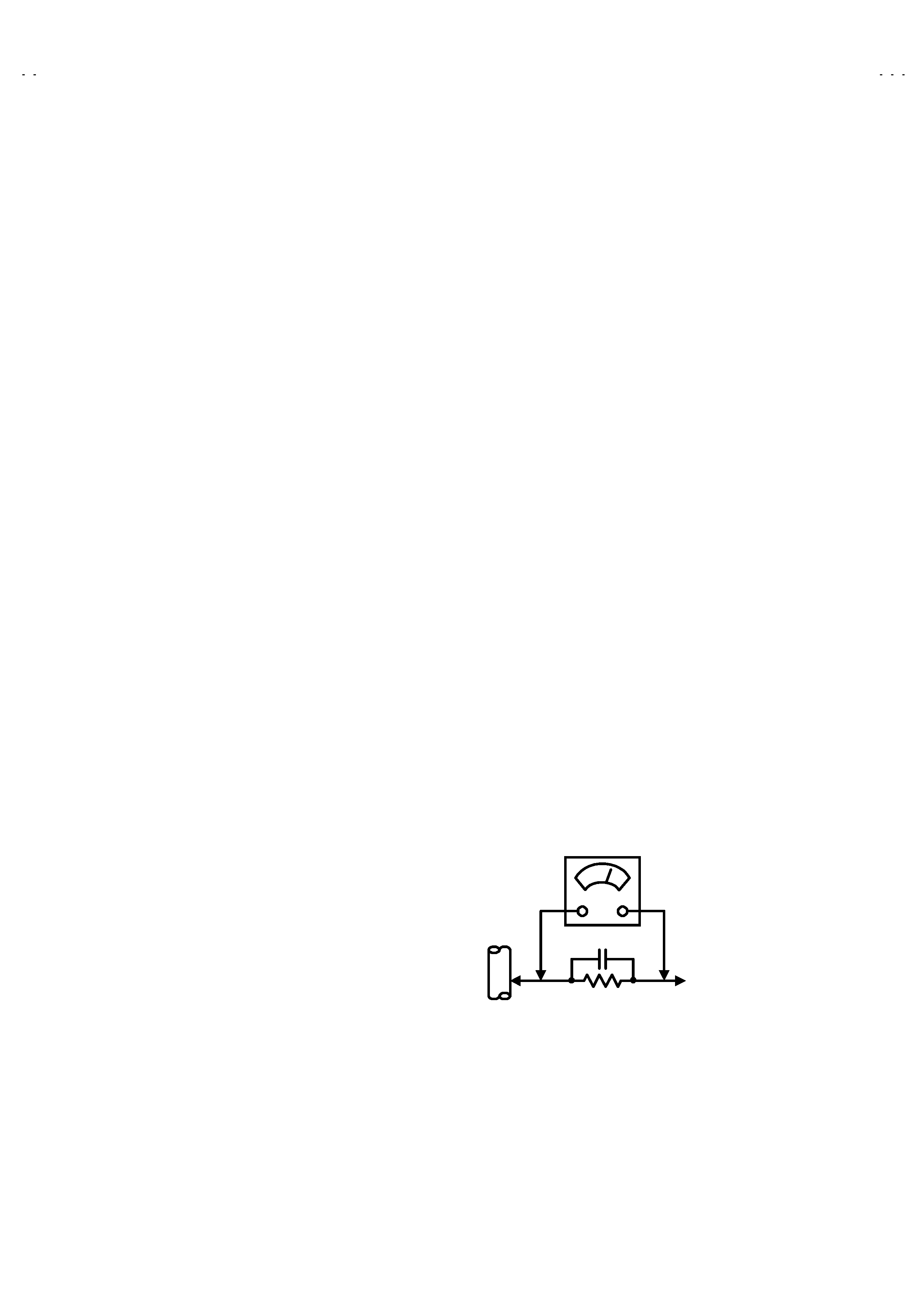
Alternate Check Method
Plug the AC line cord directly into the AC outlet (do not use a line
isolation transformer during this check.). Use an AC voltmeter
having 1000 ohms per volt or more sensitivity in the following
manner. Connect a 1500
10W resistor paralleled by a 0.15 F
AC-type capacitor between an exposed metal part and a known
good earth ground (water pipe, etc.). Measure the AC voltage
across the resistor with the AC voltmeter. Move the resistor
connection to each exposed metal part, particularly any exposed
metal part having a return path to the chassis, and measure the
AC voltage across the resistor. Now, reverse the plug in the AC
outlet and repeat each measurement. Any voltage measured
must not exceed 0.75V AC (r.m.s.). This corresponds to 0.5mA
AC (r.m.s.).
However, in tropical area, this must not exceed 0.3V AC (r.m.s.).
This corresponds to 0.2mA AC (r.m.s.).
0.15F AC-TYPE
1500
10W
GOOD EARTH GROUND
PLACE THIS PROBE
ON EACH EXPOSED
METAL PART
AC VOLTMETER
(HAVING 1000
/V,
OR MORE SENSITIVITY)
No.51879
AV21BF5ENS
AV21BF5EES
5
FEATURES
1. It is a remote controlled color television.
2. 100 programs from VHF, UHF bands or cable channels can be
preset.
3. It can tune cable channels.
4. Controlling the TV is very easy by its menu driven system.
5. It has two Euroconnector sockets for external device (such as
video recorder, video games, audio set, etc.)
6. Front AV Input available.
7. Stereo sound systems (German + Nicam) are available.
8. Full function Teletext (Fastext, Toptext).
9. It is possible to connect headphone.
10. Direct channel access.
11. APS (Automatic Programming System).
12. All programs can be named.
13. Forward or backward automatic tuning.
14. Automatic sound mute when no transmission.
15. 5 minutes after the broadcasting (closedown), the TV switches
itself automatically to stand-by mode.
MAIN DIFFERENCE LIST
MODEL No.
Parts Name
AV21BF5ENS
AV21BF5EES
MAIN PWB
VE-20073855
VE-20073865
F CARTON BOX
VE-20074340
VE-20074390
INST BOOK
VE-50021021
VE-50021020
RATING LABEL
VE-20074339
VE-20074389
TV RF system
B/G
B/G, D/K, K1
Colour system
(TV MODE)
PAL
PAL / SECAM