INSTRUCTIONS
COLOR TELEVISION
GGT0006-001A-H
0303-NIC-JMT
2003 VICTOR COMPANY OF JAPAN, LIMITED
AV-21YT11
AV-20NT11
AV-14FT11
AV-21YN11
AV-20NN11
AV-14FN11
GGT0006-21YT11-E5
5/11/03, 8:59 AM
3
2
WARNING:
TO PREVENT FIRE OR SHOCK
HAZARD, DO NOT EXPOSE
THIS APPLIANCE TO RAIN OR
MOISTURE.
CAUTION:
TO ENSURE PERSONAL SAFETY,
OBSERVE THE FOLLOWING
RULES REGARDING THE USE OF
THIS TV.
· Operate only from the power source
specified on the TV.
· Avoid damaging the power cord and main
plug. When you unplug the TV, pull it out by
the main plug. Do not pull on the power cord.
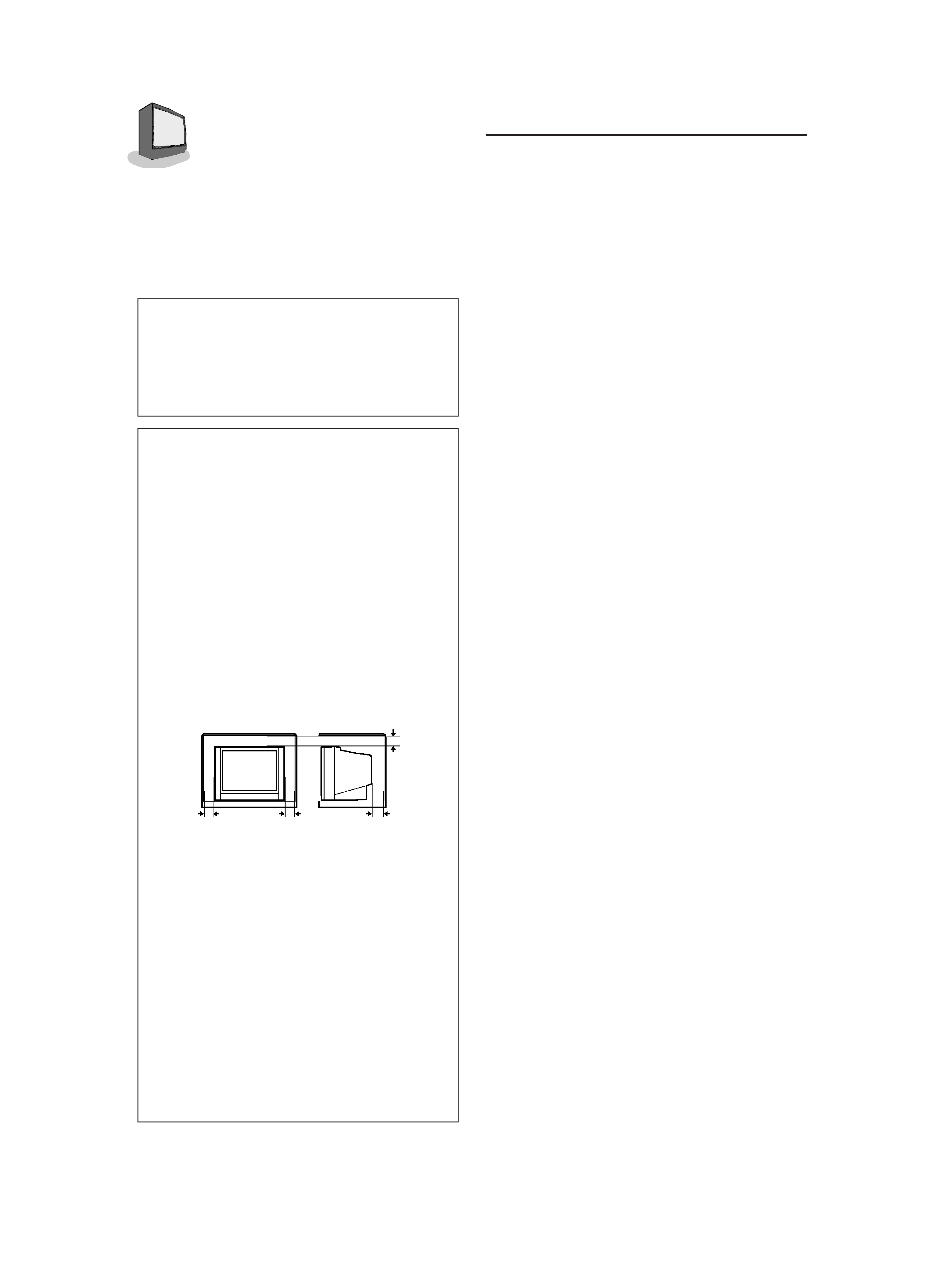
· Never block or cover the cabinet opening
for ventilation. Never install the TV where
good ventilation is unattainable. When
installing this TV, leave spaces for
ventilation around the TV more than the
minimum distances shown in the diagram.
· Do not allow objects or liquid into the
cabinet openings.
· In the event of a fault, unplug the TV and
bring to JVC service centre. Do not attempt
to repair it by yourself or remove the rear
cover.
· The surface of the TV screen is easily
damaged. Be very careful with it when
handling the TV. Should the TV screen
become soiled, wipe it with a soft dry cloth.
Never rub it forcefully. Never use any
cleaner or detergent on it.
· When you don't use this TV for a long
period of time, be sure to disconnect the
power plug from the AC outlet.
· The apparatus shall not be exposed to
dripping or splashing and that no objects
filled with liquids, such as vases, shall be
be placed on the apparatus.
TABLE OF CONTENTS
CONNECTIONS
Front & Rear Panel Diagrams ............................... 3
Indoor Antenna Connection .................................. 3
Connecting the Antenna and VCR ........................ 4
Connecting other External Devices ....................... 4
GETTING STARTED
Remote Controls .................................................... 6
Power ................................................................... 7
Adjusting Volume ................................................... 7
Changing Channels ............................................... 7
SETUP TOUR ......................................................... 8
MENU FUNCTIONS
Using the Menu ...................................................... 9
Initial Setup
Auto Tuner Setup ..................................... 10
Background ............................................. 10
Closed Caption ........................................ 10
Language (for on-screen menus) ........... 10
Noise Muting ............................................ 10
Picture Settings
Tint ........................................................... 11
Color ........................................................ 11
Picture ...................................................... 11
Bright ....................................................... 11
Detail ........................................................ 11
Sound Settings
Bass ......................................................... 12
Treble ....................................................... 12
Balance .................................................... 12
MTS (Multi-channel TV Sound) ................ 12
Some Sound Advice ................................ 12
General Items
Set Clock ................................................. 13
On/Off Timer ............................................ 13
Channel Summary ................................... 14
Set Lock Code ......................................... 15
Child Lock ................................................ 15
BUTTON FUNCTIONS
Display ................................................................. 16
Closed Caption .................................................... 16
Video Status ......................................................... 16
Sleep Timer .......................................................... 16
Hyper Surround ................................................... 16
Number Buttons (10 Key Pad) ............................ 17
100+
................................................................. 17
Muting ................................................................. 17
Menu Buttons ....................................................... 17
TV/Video ............................................................... 17
Color System ........................................................ 17
Return+ ................................................................ 18
Picture Booster .................................................... 18
APPENDICES
Troubleshooting ................................................... 19
Specifications ....................................... Back cover
15 cm
10 cm
15 cm
10 cm
Thank you for purchasing this JVC color
television.
To ensure your complete understanding,
please read this manual thoroughly be-
fore operation.
GGT0006-21YT11-E5
5/11/03, 9:04 AM
2
3
CONNECTIONS
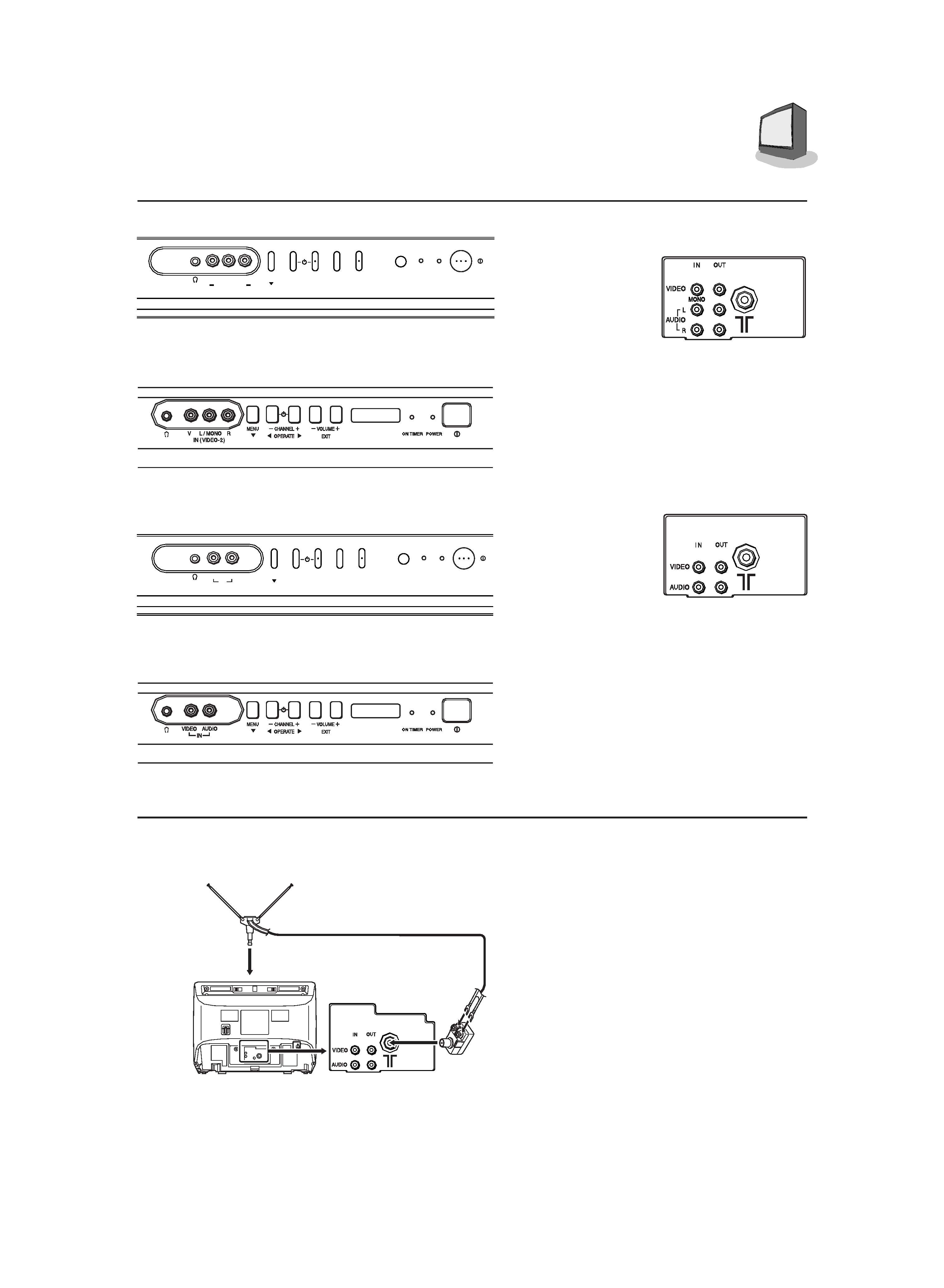
FRONT & REAR PANEL DIAGRAMS
INDOOR ANTENNA CONNECTION
To Install rod aerial:
Install into the top-rear aerial holder.
Once installed, it cannot be removed.
You can connect an indoor antenna
included.
1) Connect the indoor antenna to
the Matching adaptor and connect
the Matching adaptor to the TV RF
input.
You will receive the best reception,or
best picture, if you use connect your
TV to an outdoor antenna of a cable
output.
IN (VIDEO-2)
VR
L/MONO
POWER
ON
TIMER
MENU
VOLUME +
EXIT
CHANNEL +
OPERATE :
;
AV-21YT11 Front Panel
AV-20NT11/AV-14FT11 Front Panel
IN
VIDEO AUDIO
POWER
ON
TIMER
MENU
VOLUME +
EXIT
CHANNEL +
OPERATE :
;
AV-21YN11 Front Panel
AV-20NN11/AV-14FN11 Front Panel
AV-21YN11
AV-20NN11
AV-14FN11
Rear Panel
AV-21YT11
AV-20NT11
AV-14FT11
Rear Panel
Illustration of AV-14FN11
VHF/UHF indoor Antenna
(supplied)
Matching adaptor
(supplied)
TV
GGT0006-21YT11-E5
5/11/03, 9:04 AM
3
4
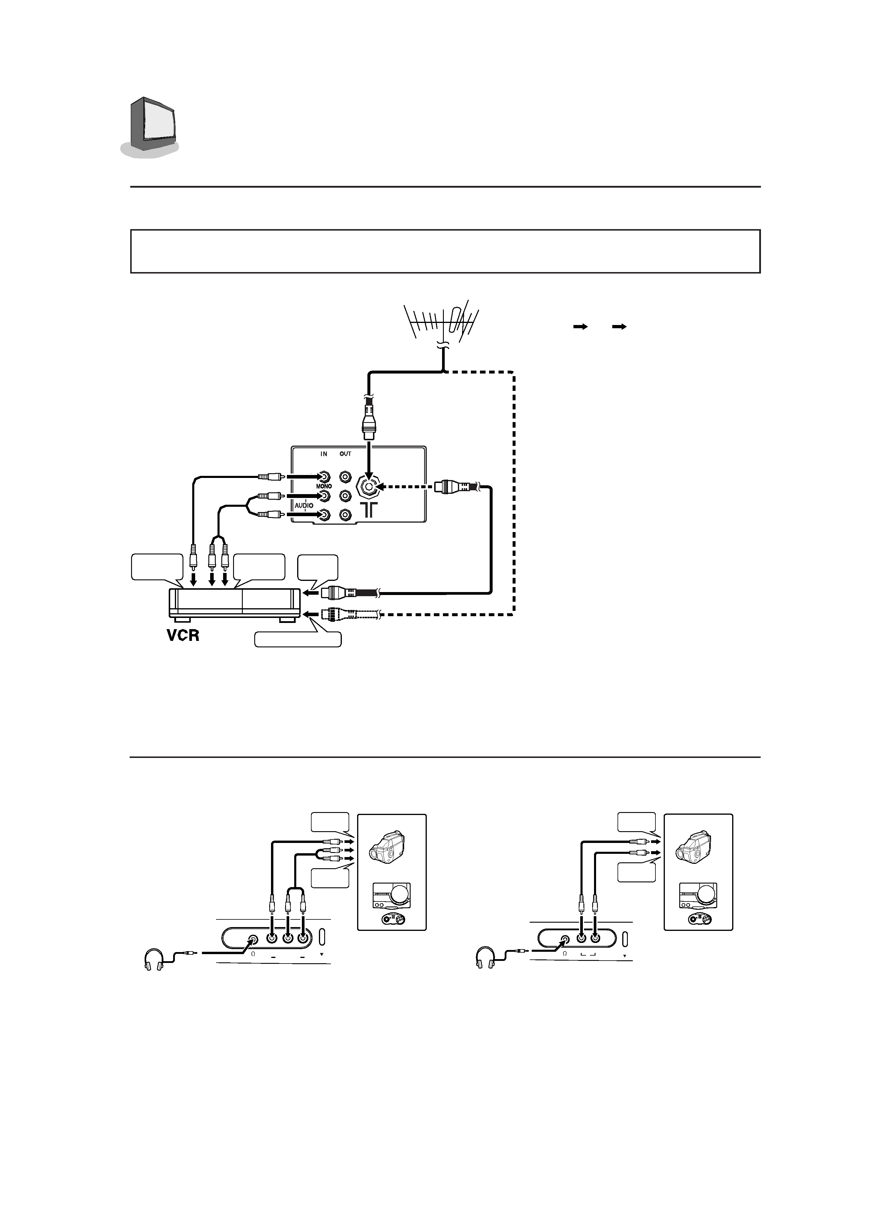
CONNECTIONS
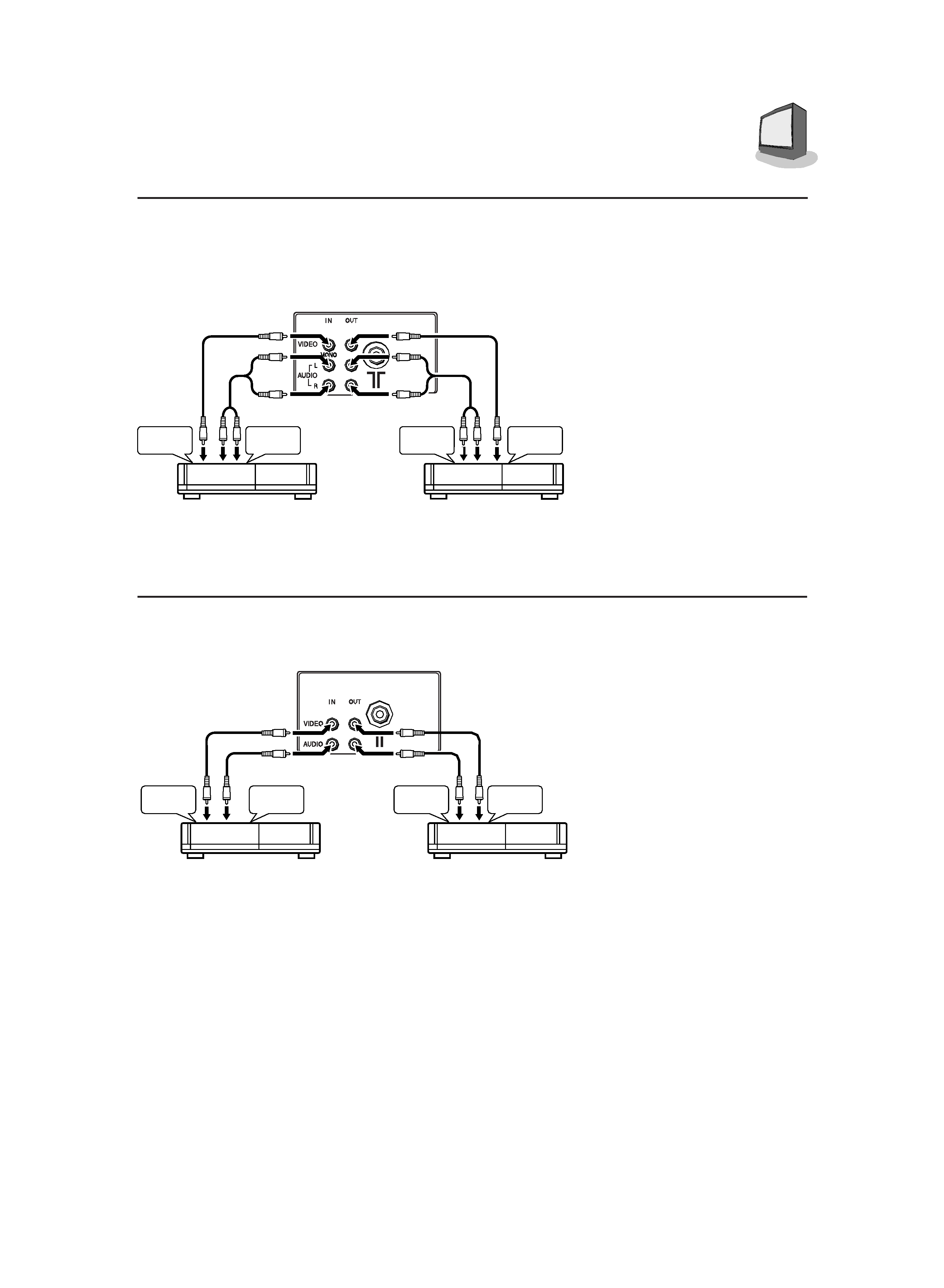
CONNECTING THE ANTENNA AND VCR
· For further details, refer to the manuals provided with the devices you are connecting.
· Connecting cables are not supplied.
If not connecting a VCR, do 1.
If connecting a VCR, proceed
1
2
3.
· You can view images from the
VCR without doing 3.
Note: When connecting mon-
aural audio to the TV,
use the L/MONO jack.
Note: The sound and picture
that you are watching
are output from VIDEO/
AUDIO (L/R) output
jacks on the rear panel.
Note: The front and rear AU-
DIO/VIDEO input jacks
are directly connected so
that input to either jack is
output through both. You
cannot provide input to
both the front and rear
jacks at the same time.
Disconnect one input, or
use one of the jacks as
an output jack only (for
monitoring or recording).
CONNECTING OTHER EXTERNAL DEVICES
Camcorder
or
TV game
To audio
output
To video
output
Headphones
MENU
IN (VIDEO-2)
VR
L/MONO
Illustration of AV-21YT11
Camcorder
Headphones
or
TV game
To audio
output
To video
output
VIDEO AUDIO
IN
MENU
Illustration of AV-21YN11
VHF/UHF outdoor antenna
1
To RF
output
To video
output
To antenna input
To audio
output
2
3
1
Illustration of AV-21YT11
Note: Use headphones with a
stereo mini jack. When
using headphones, the
speaker sound output is
disabled.
GGT0006-21YT11-E5
5/11/03, 9:04 AM
4
5
CONNECTIONS
CONNECTING OTHER EXTERNAL DEVICES
To audio
input
To video
input
VCR (for playing)
VCR (for recording)
To video
output
To audio
output
Note: When connecting mon-
aural audio to the TV,
use the L/MONO jack.
Note: The sound and picture
that you are watching
are output from VIDEO/
AUDIO (L/R) output
jacks on the rear panel.
Note: The front and rear AU-
DIO/VIDEO input jacks
are directly connected
so that input to either
jack is output through
both. You cannot pro-
vide input to both the
front and rear jacks at
the same time.
Disconnect one input, or
use one of the jacks as
an output jack only (for
monitoring or recording).
To audio
input
To video
input
VCR (for playing)
VCR (for recording)
To video
output
To audio
output
Illustration of AV-21YT11
Illustration of AV-21YN11
GGT0006-21YT11-E5
5/11/03, 9:04 AM
5