No. 51911
Sept. 2001
AV-20F702
COPYRIGHT © 2001 VICTOR COMPANY OF JAPAN, LTD.
AV-20F702
CONTENTS
! SPECIFICATIONS
2
OPERATING INSTRUCTIONS (APPENDED)
! SAFETY PRECAUTIONS
3
! SPECIFIC SERVICE INSTRUCTIONS
4
! SERVICE ADJUSTMENTS
8
! GUIDE FOR REPAIRING
13
STANDARD CIRCUIT DIAGRAM (APPENDED)
! PARTS LIST
20
SERVICE MANUAL
COLOUR TELEVISION
MC-Service
No.51911
2
AV-20F702
SPECIFICATIONS
Items
Contents
Dimensions (W~
~
~
~H~
~
~
~D)
59.0cm~44.4cm~49.85cm
Mass
50.6Ibs
TV System and Color system
TV RF System
Color System
CCIR(M)
NTSC
TV Receiving Channels and Frequency
VHF
UHF
CATV
2-13
14-69
01-97 (5A)-(A-3)
98-99 (A-2)-(A-1)
14-22 (A)-(I)
23-36 (J)-(W)
37-65 (AA)-(FFF)
66-125 (GGG)-(125)
TV/CATV Total Channel
180 Channels
Intermediate Frequency
Video IF Carrier
Sound IF Carrier
Color Sub Carrier
45.75 MHz
41.25 MHz (4.5MHz)
3.58 MHz
Power Input
120V AC, 60Hz
Power Consumption
105W
Picture Tube
20
Speaker
2" x 4-3/4", 8 ohm x 2
Audio Power Output
2.5 W + 2.5 W
Input (1 / 2 /3)
Video
: 1Vp-p 75ohm (RCA pin jack)
Audio
: 8dB, 47kohm (RCA pin jack)
S-Video Y : 1.0Vp-p, 75 ohm
C : 0.3Vp-p, 75 ohm
Component Input
Y: 1.0Vp-p, 75 ohm
PB: 0.7Vp-p, 75 ohm
PR: 0.7Vp-p, 75 ohm
Antenna terminal
75¶ (VHF/UHF) Terminal, F-Type Connector
Remote Control Unit
RM-C309G
Design & specification are subject to change without notice.
No.51911
3
AV-20F702
SAFETY PRECAUTIONS
SERVICING NOTICES ON CHECKING
6. AVOID AN X-RAY
1. KEEP THE NOTICES
As for the places which need special attentions,
they are indicated with the labels or seals on the
cabinet, chassis and parts. Make sure to keep the
indications and notices in the operation manual.
3. USE THE DESIGNATED PARTS
5. TAKE CARE TO DEAL WITH THE
CATHODE-RAY TUBE
Safety is secured against an X-ray by consider-
ing about the cathode-ray tube and the high
voltage peripheral circuit, etc.
Therefore, when repairing the high voltage pe-
ripheral circuit, use the designated parts and
make sure not modify the circuit.
Repairing except indicates causes rising of high
voltage, and it emits an X-ray from the cathode-
ray tube.
Please include the following informations when you order parts. (Particularly the VERSION LETTER.)
1. MODEL NUMBER and VERSION LETTER
The MODEL NUMBER can be found on the back of each product and the VERSION LETTER can be
found at the end of the SERIAL NUMBER.
2. PART NO. and DESCRIPTION
You can find it in your SERVICE MANUAL.
HOW TO ORDER PARTS
Inferior silicon grease can damage IC's and transistors.
When replacing an IC's or transistors, use only specified silicon grease (YG6260M).
Remove all old silicon before applying new silicon.
IMPORTANT
2. AVOID AN ELECTRIC SHOCK
There is a high voltage part inside. Avoid an
electric shock while the electric current is
flowing.
The parts in this equipment have the specific
characters of incombustibility and withstand
voltage for safety. Therefore, the part which is
replaced should be used the part which has
the same character.
Especially as to the important parts for safety
which is indicated in the circuit diagram or the
table of parts as a
mark, the designated
parts must be used.
4. PUT PARTS AND WIRES IN THE
ORIGINAL POSITION AFTER
ASSEMBLING OR WIRING
There are parts which use the insulation
material such as a tube or tape for safety, or
which are assembled in the condition that
these do not contact with the printed board.
The inside wiring is designed not to get closer
to the pyrogenic parts and high voltage parts.
Therefore, put these parts in the original
positions.
In the condition that an explosion-proof cathode-
ray tube is set in this equipment, safety is
secured against implosion. However, when
removing it or serving from backward, it is
dangerous to give a shock. Take enough care to
deal with it.
PERFORM A SAFETY CHECK AFTER
SERVICING
7.
Confirm that the screws, parts and wiring which
were removed in order to service are put in the
original positions, or whether there are the
portions which are deteriorated around the
serviced places serviced or not. Check the
insulation between the antenna terminal or
external metal and the AC cord plug blades.
And be sure the safety of that.
(INSULATION CHECK PROCEDURE)
1.
2.
3.
4.
Unplug the plug from the AC outlet.
Remove the antenna terminal on TV and turn
on the TV.
Insulation resistance between the cord plug
terminals and the eternal exposure metal
[Note 2] should be more than 1M ohm by
using the 500V insulation resistance meter
[Note 1].
If the insulation resistance is less than 1M
ohm, the inspection repair should be
required.
[Note 1]
If you have not the 500V insulation
resistance meter, use a Tester.
[Note 2]
External exposure metal: Antenna terminal
Earphone jack
Licensed by BBE Sound, Inc. under USP4638258 and 4482866.
BBE and BBE symbol are registered trademarks of BBE
Sound, Inc.
MC-Service
No.51911
4
AV-20F702
SPECIFIC SERVICE INSTRUCTIONS
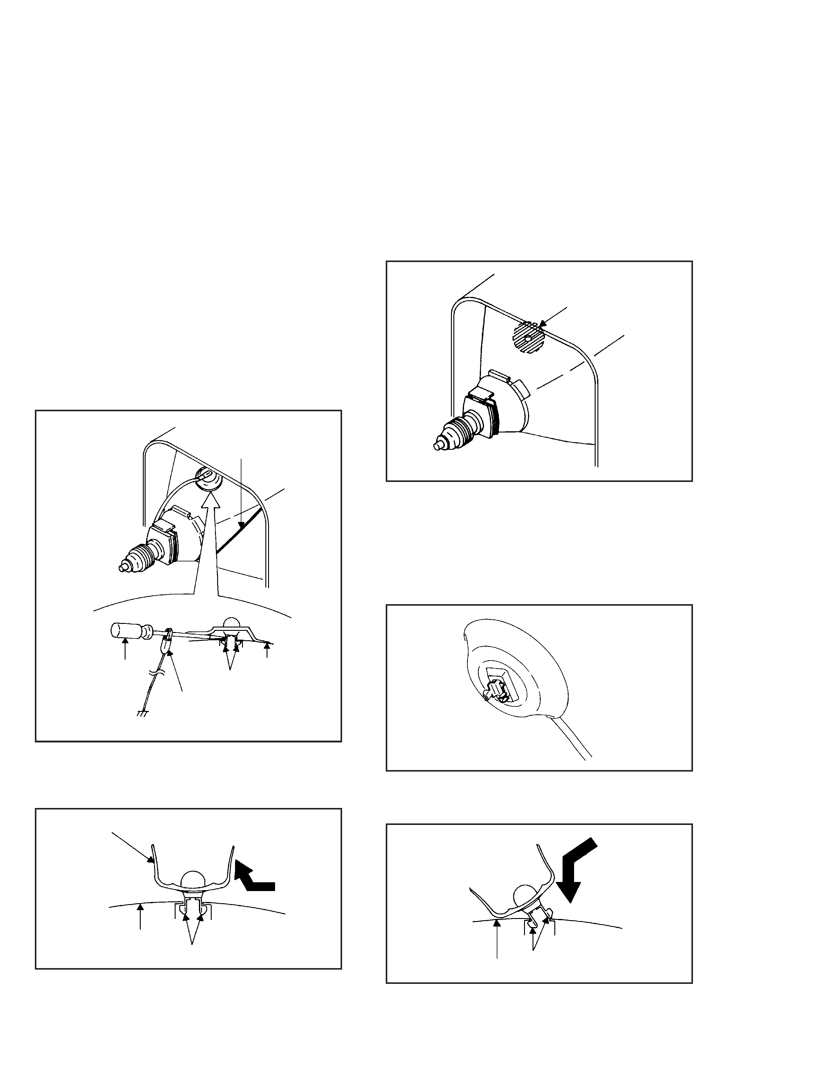
1. REMOVAL OF ANODE CAP
Read the following NOTED items before starting work.
After turning the power off there might still be a potential
voltage that is very dangerous. When removing the
Anode Cap, make sure to discharge the Anode Cap's
potential voltage.
Do not use pliers to loosen or tighten the Anode Cap
terminal, this may cause the spring to be damaged.
*
*
REMOVAL
1. Follow the steps as follows to discharge the Anode Cap.
(Refer to Fig. 1-1.)
Connect one end of an Alligator Clip to the metal part of a
flat-blade screwdriver and the other end to ground.
While holding the plastic part of the insulated Screwdriver,
touch the support of the Anode with the tip of the
Screwdriver.
A cracking noise will be heard as the voltage is discharged.
Flip up the sides of the Rubber Cap in the direction of the
arrow and remove one side of the support.
(Refer to Fig. 1-2.)
2.
DISASSEMBLY INSTRUCTIONS
GND on the CRT
Screwdriver
Alligator Clip
Support
CRT
GND on the CRT
Rubber Cap
CRT
Support
Fig. 1-1
Fig. 1-2
3. After one side is removed, pull in the opposite direction to
remove the other.
NOTE
Take care not to damage the Rubber Cap.
INSTALLATION
1. Clean the spot where the cap was located with a small
amount of alcohol. (Refer to Fig. 1-3.)
Location of Anode Cap
Fig. 1-3
NOTE
Confirm that there is no dirt, dust, etc. at the spot where
the cap was located.
2.
3.
Arrange the wire of the Anode Cap and make sure the
wire is not twisted.
Turn over the Rubber Cap. (Refer to Fig. 1-4.)
Fig. 1-4
4. Insert one end of the Anode Support into the anode button,
then the other as shown in Fig. 1-5.
5.
6.
Confirm that the Support is securely connected.
Put on the Rubber Cap without moving any parts.
CRT
Support
Fig. 1-5
No.51911
5
AV-20F702
Masking Tape
(Cotton Tape)
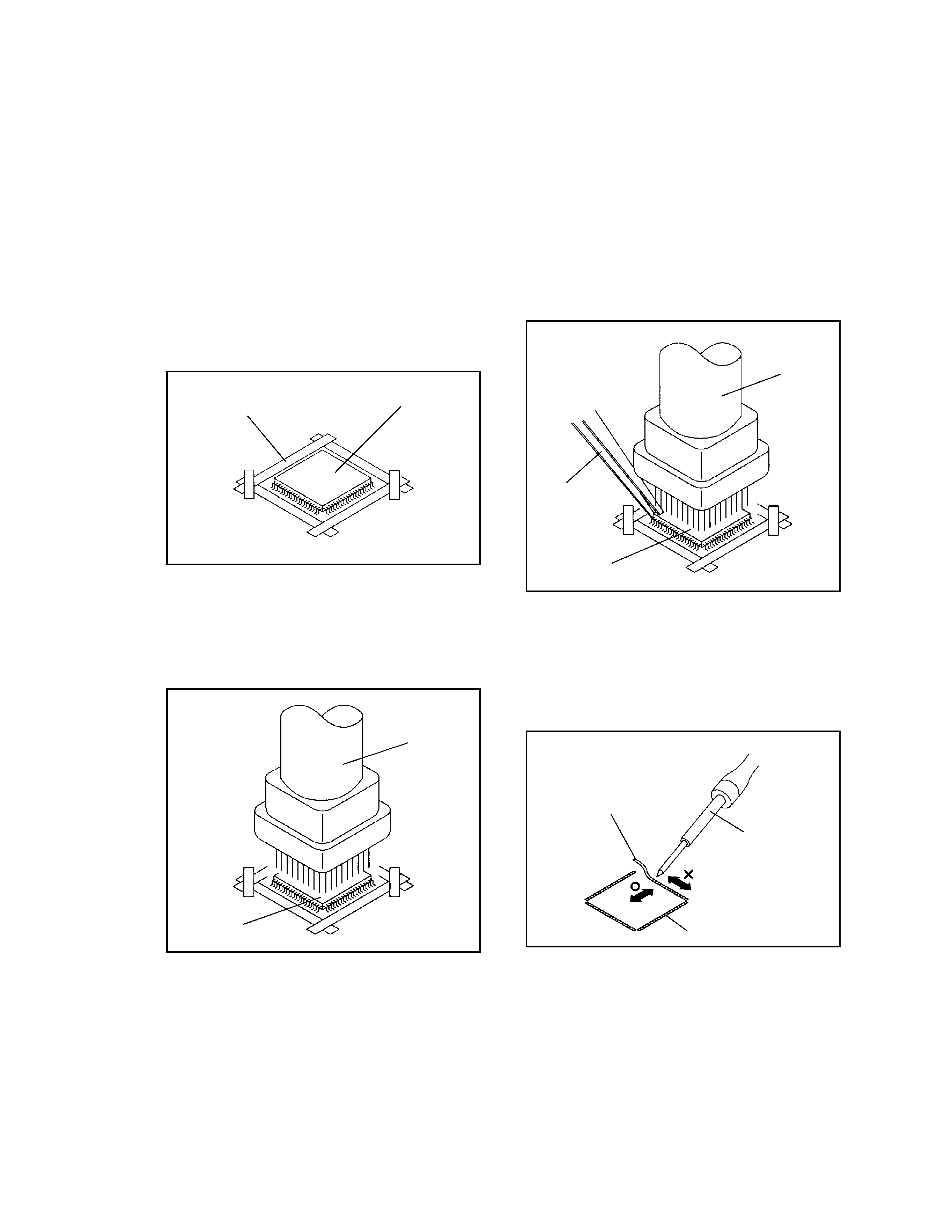
DISASSEMBLY INSTRUCTIONS
2.
REMOVAL
IC
Put the Masking Tape (cotton tape) around the Flat
Package IC to protect other parts from any damage.
(Refer to Fig. 2-1.)
1.
Fig. 2-1
NOTE
REMOVAL AND INSTALLATION OF
FLAT PACKAGE IC
Some ICs on the PCB are affixed with glue, so be
careful not to break or damage the foil of each IC
leads or solder lands under the IC when removing it.
NOTE
Masking is carried out on all the parts located within
10 mm distance from IC leads.
Blower type IC
desoldering machine
IC
Heat the IC leads using a blower type IC desoldering
machine. (Refer to Fig. 2-2.)
2.
Fig. 2-2
NOTE
Do not add the rotating and the back and forth
directions force on the IC, until IC can move back and
forth easily after desoldering the IC leads completely.
When IC starts moving back and forth easily after
desoldering completely, pickup the corner of the IC using
a tweezers and remove the IC by moving with the IC
desoldering machine. (Refer to Fig. 2-3.)
3.
Blower type IC
desoldering
machine
IC
Fig. 2-3
Tweezers
Peel off the Masking Tape.
4.
Absorb the solder left on the pattern using the Braided
Shield Wire. (Refer to Fig. 2-4.)
5.
NOTE
Do not move the Braided Shield Wire in the vertical
direction towards the IC pattern.
Braided Shield Wire
Soldering Iron
Fig. 2-4
IC pattern
MC-Service