COLOUR TELEVISION
INSTRUCTIONS
Thank you for purchasing this JVC
colour television.
To ensure your complete
understanding, please read this
manual thoroughly before operation.
AV-14A10
AV-21D10
AV-14ATG2
AV-21DM10
AV-14FTG2
AV-21DTG2
AV-20NTG2
AV-21LT1
AV-21ATG2
AV-21LTG1
15 cm
10 cm
15 cm
10 cm
CAUTION:
· TO ENSURE PERSONAL SAFETY, OBSERVE THE FOLLOWING RULES
REGARDING THE USE OF THIS TV.
· Operate only from the power source specified on the TV.
· Avoid damaging the power plug and power cord.
· Avoid improper installation and never position this TV where good ventilation is
unattainable. When installing this TV
distance recommendations must be
maintained between the floor and
wall, as well as installment in a tightly
enclosed area or piece of furniture.
Adhere to the minimum distance
guidelines shown for safe operation.
· Do not allow objects or liquid into the cabinet openings.
· In the event of a fault, unplug this TV and call a service technician. Do not
attempt to repair it by yourself or remove the rear cover.
· When you don't use this TV for a long period of time, be sure to disconnect the
power plug from the AC outlet.
LCT0994-001B-H
0701-Ki-NV-JMT
2001 VICTOR COMPANY OF JAPAN, LIMITED
Locations ................................
2
Preparation .............................
3
Basic operation ......................
9
Remote control buttons
and functions ........................
10
Using the TV's menus ..........
13
Using the button on the TV ...
16
Troubleshooting ...................
18
Specifications .......................
19
Contents
WARNING:
TO PREVENT FIRE OR SHOCK
HAZARD, DO NOT EXPOSE THIS
APPLIANCE TO RAIN OR
MOISTURE.
LCT0994-001B-H_cover
7/3/1, 1:18 PM
1
Black
2
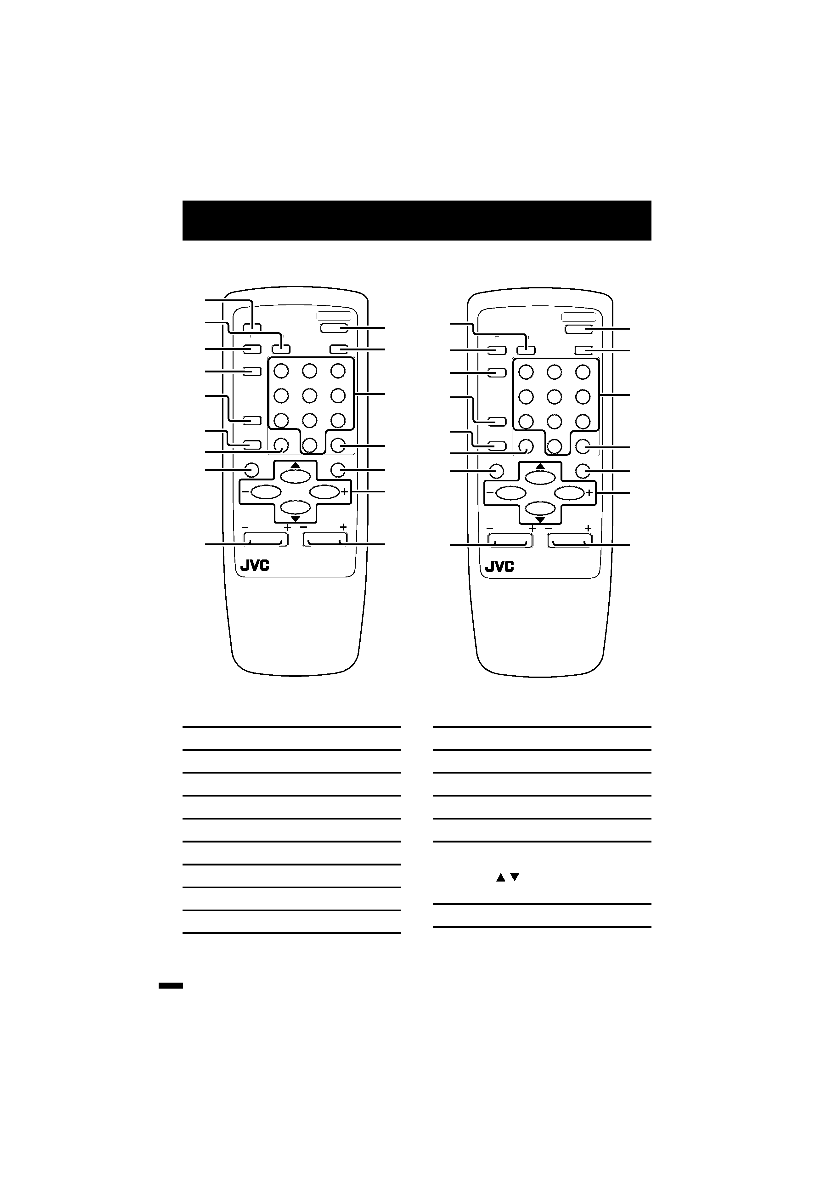
Locations
1 ECO SENSOR button
p.11
2 SOUND SYSTEM button
p.10
3 COLOUR SYSTEM button
p.10
4 TV/VIDEO button
p.9
5 OFF TIMER button
p.11
6 CHANNEL SCAN button
p.12
7 RETURN + button
p.12
8 DISPLAY button
p.11
9 CHANNEL /+ buttons
p.9
POWER
12
3
45
6
78
9
RETURN
+
0
-/--
PICTURE
MODE
SYSTEM
COLOUR
TV/VIDEO
CHANNEL
SCAN
OFF
TIMER
ECO
SENSOR
DISPLAY
MENU
VOLUME
MUTING
SOUND
5
6
!
@
9
3
2
1
8
4
7
#
~
-
0
=
CHANNEL
REMOTE CONTROL UNIT
RM-C364GY
0 POWER button
p.5,9
- PICTURE MODE button
p.10
= Number buttons
p.9
~ -/-- button
p.9
! MUTING button
p.11
@ MENU buttons
· MENU
/
buttons
· MENU /+ buttons
# VOLUME /+ buttons
p.9
RM-C364GY
RM-C360GY
POWER
12
3
45
6
78
9
RETURN
+
0
-/--
PICTURE
MODE
SYSTEM
COLOUR
TV/VIDEO
CHANNEL
SCAN
OFF
TIMER
DISPLAY
MENU
VOLUME
MUTING
SOUND
5
6
!
@
9
3
2
8
4
7
#
~
-
0
=
CHANNEL
REMOTE CONTROL UNIT
RM-C360GY
LCT0994-001B-H
6/29/01, 4:46 PM
2
Black
3
Preparation
1. Connecting the aerial and external devices
Notes: .........................................................................................................................
· For further details, refer to the manuals provided with the devices you are connecting.
· Connecting cables are not supplied.
· The front and rear AUDIO/VIDEO input jacks are directly connected so that input to either
jack is output through both. You cannot provide input to both the front and rear jacks at the
same time. Disconnect one input, or use one of the jacks as an output jack only (for
monitoring or recording).
· The rod aerial is supplied with the AV-14A10/AV-14ATG2/AV-14FTG2.
....................................................................................................................................
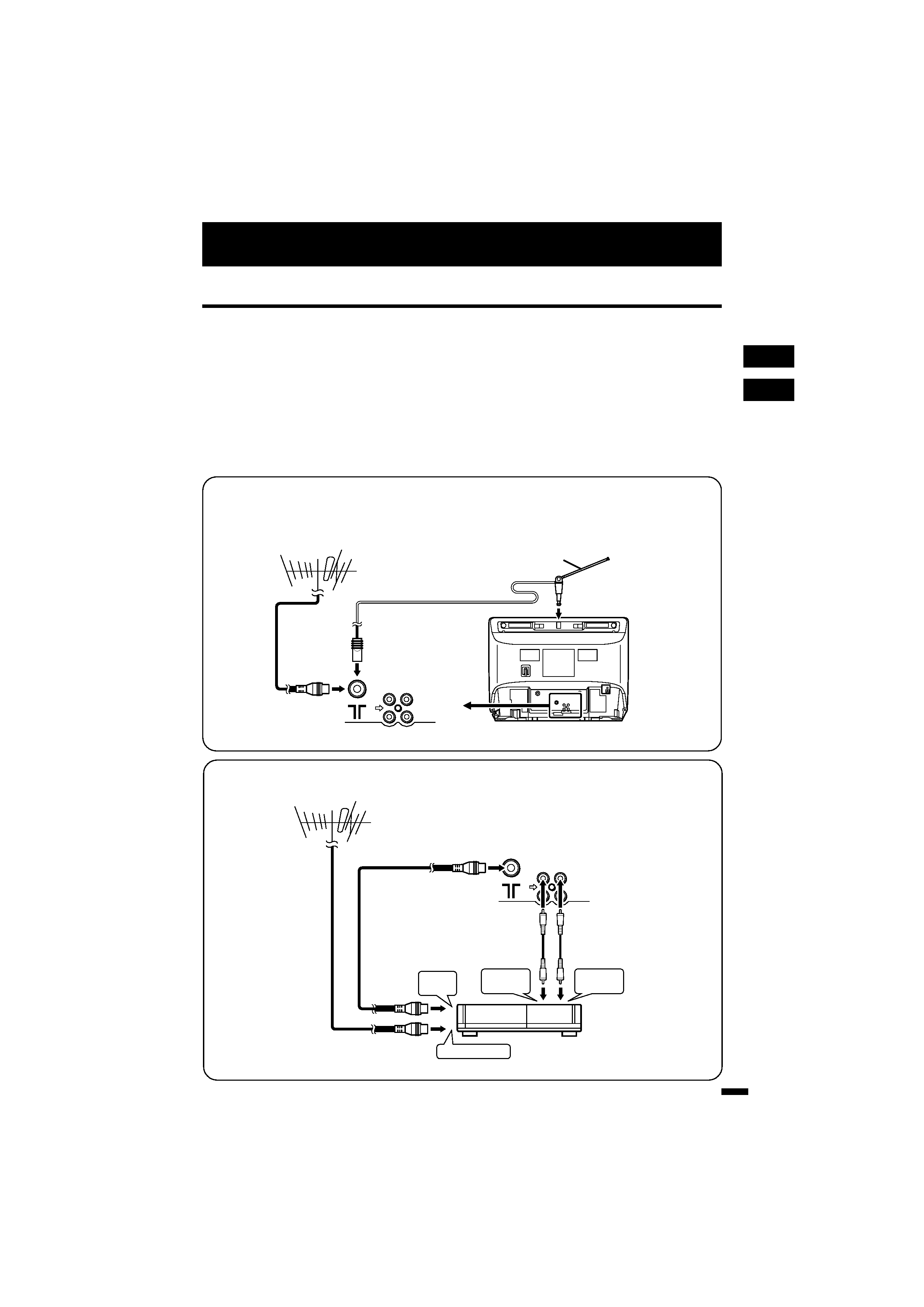
I Connecting the aerial and VCR
Connecting the aerial
To install rod aerial:
Install into the top-rear aerial holder. Once installed, it cannot be removed.
To RF
output
To video
output
To aerial input
To audio
output
3
2
VCR
VHF/UHF outdoor aerial
1
VIDEO
AUDIO
IN
OUT
· Illustration of AV-14FTG2.
Connecting the aerial and VCR
· Illustration of AV-14FTG2.
VHF/UHF outdoor aerial
VIDEO
AUDIO
IN
OUT
Indoor aerial
Rod aerial
LCT0994-001B-H
6/29/01, 4:46 PM
3
Black
4
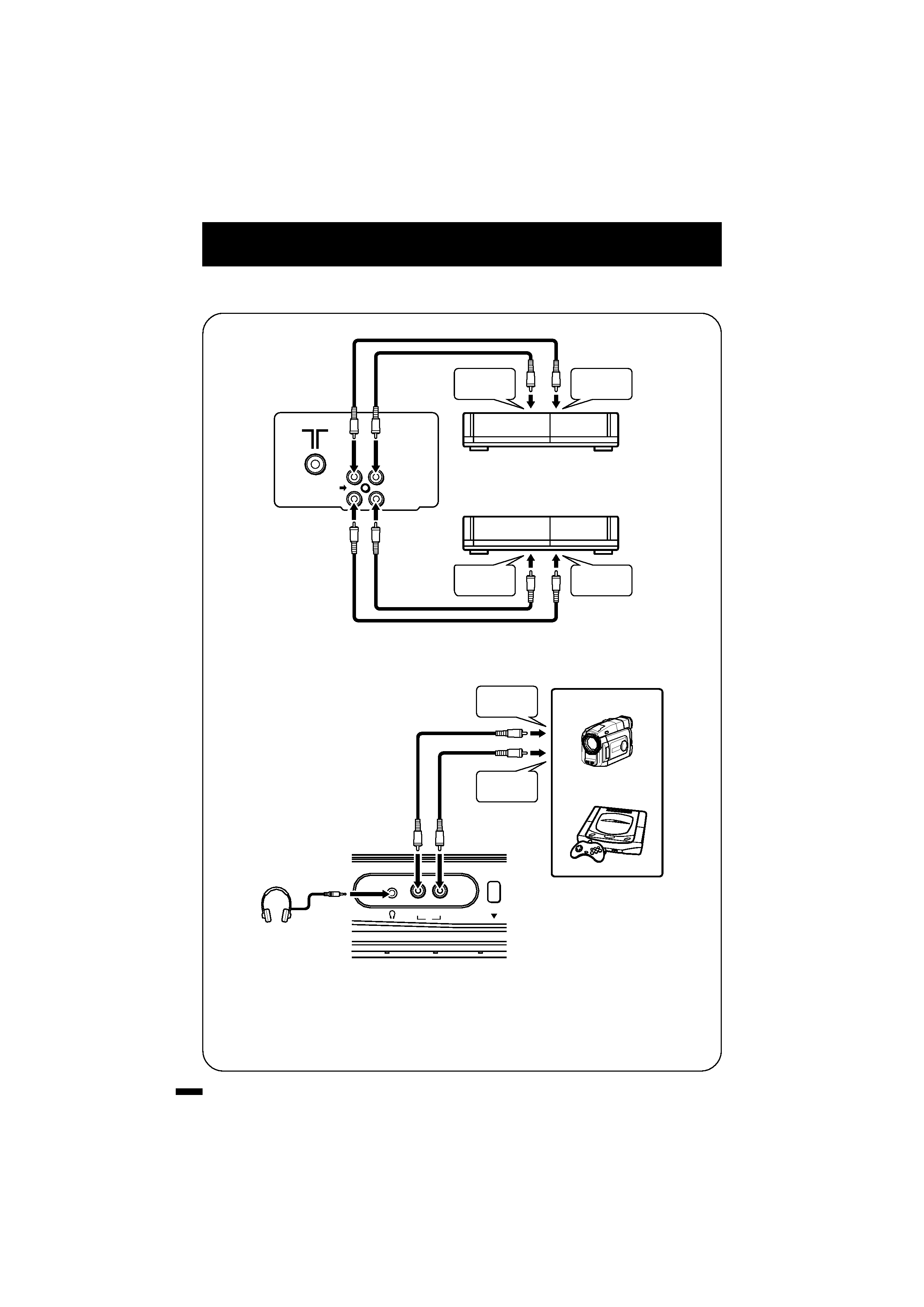
I Connecting other external devices
Preparation
Note: ..................................................................................................................
· Use the headphones with a stereo mini jack (3.5 mm in diameter). When you connect
the headphones, the TV speakers go off.
...........................................................................................................................
· Illustration of AV-21DTG2.
VIDEO
IN
OUT
AUDIO
VCR (for recording)
VCR (for playing)
To audio
output
To video
output
To audio
input
To video
input
· Illustration of AV-21DTG2.
MENU
VIDEO
AUDIO
IN
To audio
output
To video
output
Headphones
Camcorder
or
TV game
LCT0994-001B-H
6/29/01, 4:46 PM
4
Black
5
Preparation
CAUTION: ...........................................
· Follow the cautions printed on the
batteries.
............................................................
Notes: .................................................
· Use AA/R6/UM-3 dry cell batteries.
· If the remote control does not work
properly, fit new batteries.
The supplied batteries are for testing, not
regular use.
............................................................
4. Turning your TV on
1. Press the Main power button on the TV to turn the TV's main power
on.
The POWER lamp or POWER/ON TIMER lamp lights.
If image does not appear:
Your TV is in the standby mode. Press the POWER button on the remote control
to turn your TV on.
· You can also turn on your TV by pressing the CHANNEL /+ button on your TV.
To turn your TV off:
Press the POWER button on the remote control. Your TV enters the standby
mode.
To turn the TV's main power off:
Press the Main power button on the TV.
2. Connecting the power cord
Insert the Power plug into an AC outlet.
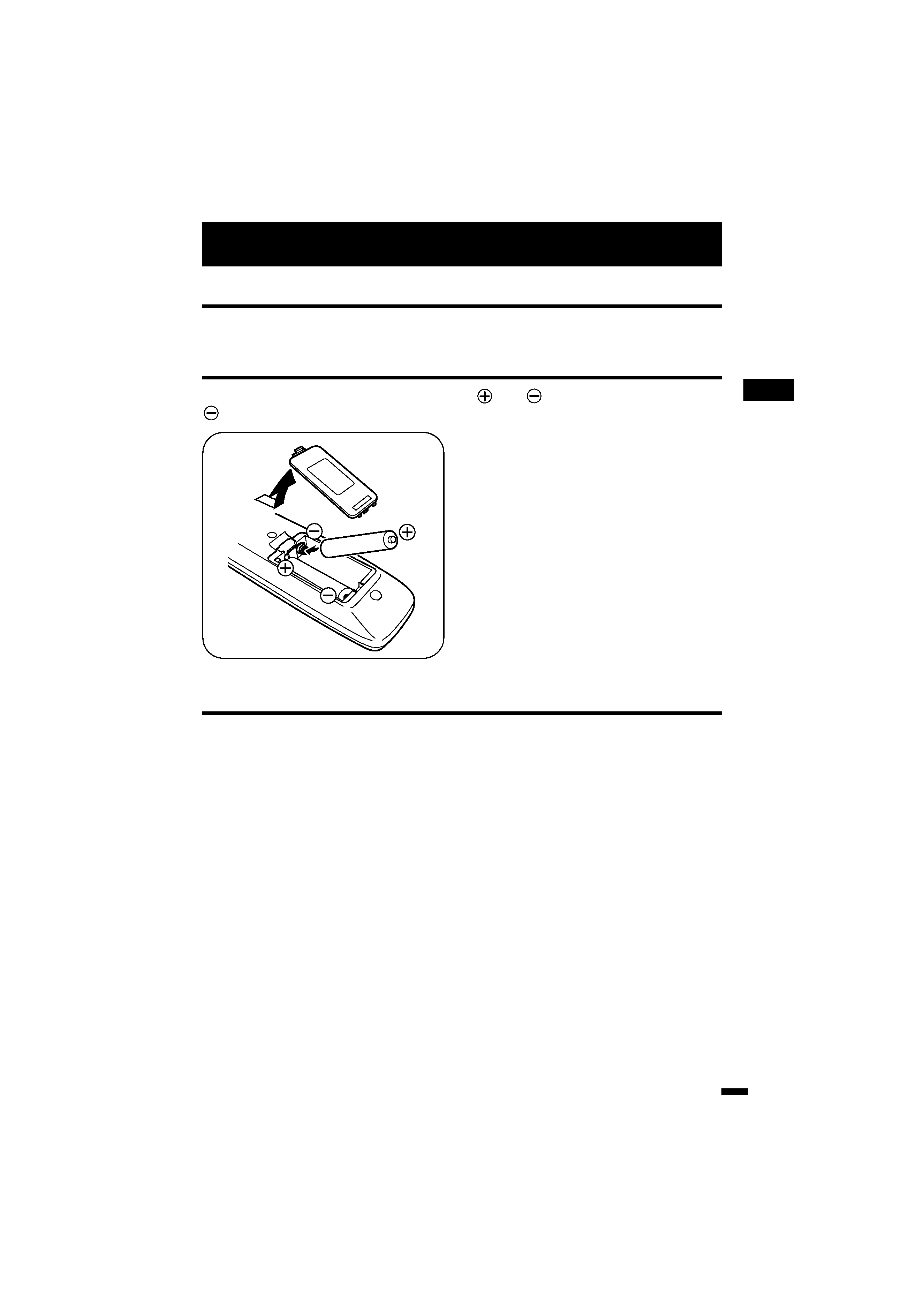
3. Inserting batteries into the remote control
Correctly insert two batteries, observing the
and
polarities and inserting the
end first.
LCT0994-001B-H
6/29/01, 4:46 PM
5
Black