SERVICE MANUAL
COPYRIGHT © 2003 VICTOR COMPANY OF JAPAN, LIMITED
No.52122
2003/6
COLOUR TELEVISION
52122
2003
6
AV-14FN11/P, AV-14FT11/P,
AV-20NN11/P, AV-20NT11/P
TABLE OF CONTENTS
1
PRECAUTION. . . . . . . . . . . . . . . . . . . . . . . . . . . . . . . . . . . . . . . . . . . . . . . . . . . . . . . . . . . . . . . . . . . . . . . . . 1-3
2
SPECIFIC SERVICE INSTRUCTIONS . . . . . . . . . . . . . . . . . . . . . . . . . . . . . . . . . . . . . . . . . . . . . . . . . . . . . . 1-4
3
DISASSEMBLY . . . . . . . . . . . . . . . . . . . . . . . . . . . . . . . . . . . . . . . . . . . . . . . . . . . . . . . . . . . . . . . . . . . . . . . 1-5
4
ADJUSTMENT . . . . . . . . . . . . . . . . . . . . . . . . . . . . . . . . . . . . . . . . . . . . . . . . . . . . . . . . . . . . . . . . . . . . . . . 1-12
5
TROUBLE SHOOTING . . . . . . . . . . . . . . . . . . . . . . . . . . . . . . . . . . . . . . . . . . . . . . . . . . . . . . . . . . . . . . . . . 1-31
BASIC CHASSIS
CJ
[AV-14FN11/P]
[AV-14FT11/P]
[AV-20NN11/P]
[AV-20NT11/P]
RM-C372GY
[AV-14FN11/P]
[AV-14FT11/P]
RM-C373GY
[AV-20NN11/P]
[AV-20NT11/P]
1-2 (No.52122)
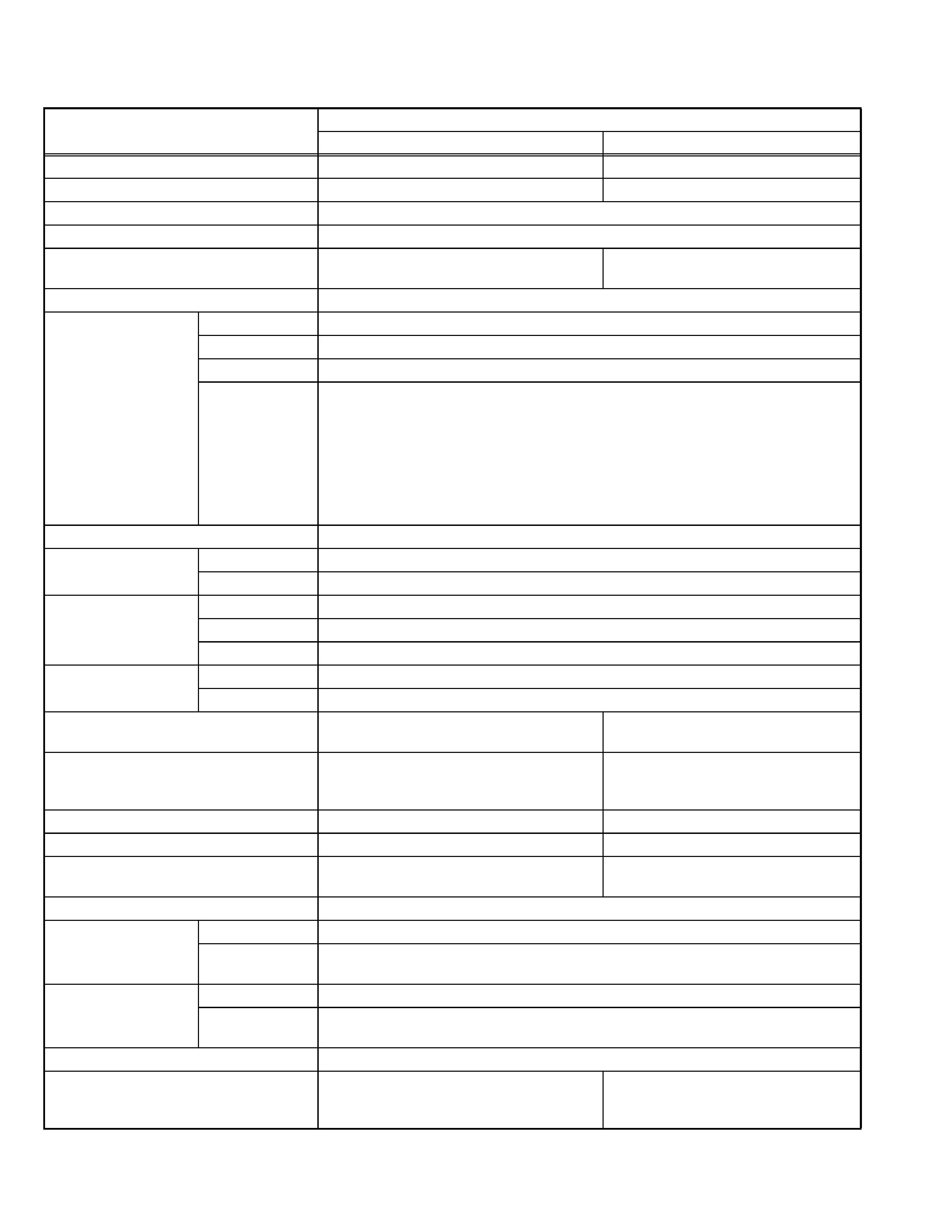
SPECIFICATION
Design & specifications are subject to change without notice.
Items
Contents
AV-14FN11/P, AV-14FT11/P
AV-20NN11/P, AV-20NT11/P
Dimensions (W
× H × D)
462mm
× 340.5mm × 375mm
619mm
× 458mm × 488mm
Mass
10.0 kg
19.0 kg
TV RF System
CCIR(M)&(N)
Colour System
NTSC / PAL-M / PAL-N
Sound System
BTSC(Multi Channel Sound)
[AV-14FT11/P]
BTSC(Multi Channel Sound)
[AV-20NT11/P]
Teletext System
Closed caption (CC1-CC4 / T1-T4)
TV Receiving Channels
and Frequency
VHF LOW 02ch~06ch : 54MHz~88MHz
VHF HIGH 07ch~13ch : 174MHz~216MHz
UHF 14ch~69ch : 470MHz~806MHz
CATV 54MHz~804MHz
Low Band : 02~06, A-8 by 02~06&01
High Band : 07~13 by 07~13
Mid Band : A~I by 14~22
Super Band : J~W by 23~36
Hyper Band : W+1~W+28 by 37~64
Ultra Band : W+29~W+84 by 65~125
Sub Mid Band : A8, A4~A1 by 01, 96~99
TV / CATV Total Channel
181 channels
Intermediate Frequency
Video IF Carrier 45.75 MHz
Sound IF Carrier 41.25 MHz (4.5MHz)
Colour Sub Carrier
NTSC 3.579545MHz
PAL-M 3.57561149MHz
PAL-N 3.58205625MHz
Power Input
Rated Voltage AC110V~AC240V, 50Hz/60Hz
Operating Voltage AC90V~AC260V, 50Hz/60Hz
Power Consumption
48W [AV-14FN11/P]
52W [AV-14FT11/P]
59W [AV-20NN11/P]
62W [AV-20NT11/P]
Picture Tube
Visible size : 34cm
[measured diagonally]
W:28.7cm
× H:21.7cm
Visible size : 48cm
[measured diagonally]
W:41.2cm
× H:31.2cm
High Voltage
26.5kV ±1kV (at zero beam current)
Speaker
5cm
× 9cm Oval type × 2
5cm
× 12cm Oval type × 2
Audio Power Output
3W (monaural) [AV-14FN11/P]
3W+3W (stereo) [AV-14FT11/P]
3W (monaural) [AV-20NN11/P]
3W+3W (stereo) [AV-20NT11/P]
Antenna Terminal (VHF / UHF)
75
unbalanced coaxial, F-type connector
Input
Video input 1V(p-p), negative sync, 75
, RCA pin jack × 2
Audio input 500mV(rms) (-4dBs), high impedance, RCA pin jack
× 2 [AV-14FN11/P,AV-20NN11/P]
500mV(rms) (-4dBs), high impedance, RCA pin jack
× 4 [AV-14FT11/P,AV-20NT11/P]
Output
Video output 1V(p-p), negative sync, 75
, RCA pin jack × 1
Audio output 500mV(rms) (-4dBs), high impedance, RCA pin jack
× 1 [AV-14FN11/P,AV-20NN11/P]
500mV(rms) (-4dBs), high ismpedance, RCA pin jack
× 2 [AV-14FT11/P,AV-20NT11/P]
Headphone Jack
3.5mm mini jack
× 1
Remote Control Unit
RM-C372GY [AV-14FN11/P]
RM-C373GY [AV-14FT11/P]
(AA/R6/UM-3 battery
× 2)
RM-C372GY [AV-20NN11/P]
RM-C373GY [AV-20NT11/P]
(AA/R6/UM-3 battery
× 2)
(No.52122)1-3
SECTION 1
PRECAUTION
1.1
SAFETY PRECAUTIONS
(1) The design of this product contains special hardware,
many circuits and components specially for safety
purposes. For continued protection, no changes should be
made to the original design unless authorized in writing by
the manufacturer. Replacement parts must be identical to
those used in the original circuits. Service should be
performed by qualified personnel only.
(2) Alterations of the design or circuitry of the products should
not be made. Any design alterations or additions will void
the manufacturer's warranty and will further relieve the
manufacturer of responsibility for personal injury or
property damage resulting therefrom.
(3) Many electrical and mechanical parts in the products have
special
safety-related
characteristics.
These
characteristics are often not evident from visual inspection
nor can the protection afforded by them necessarily be
obtained by using replacement components rated for
higher voltage, wattage, etc. Replacement parts which
have these special safety characteristics are identified in
the parts list of Service manual. Electrical components
having such features are identified by shading on the
schematics and by (
) on the parts list in Service
manual. The use of a substitute replacement which does
not
have
the
same
safety
characteristics
as
the
recommended replacement part shown in the parts list of
Service manual may cause shock, fire, or other hazards.
(4) Don't short between the LIVE side ground and
ISOLATED (NEUTRAL) side ground or EARTH side
ground when repairing.
Some model's power circuit is partly different in the GND.
The difference of the GND is shown by the LIVE : (
) side
GND, the ISOLATED (NEUTRAL) : (
) side GND and
EARTH : (
) side GND.
Don't short between the LIVE side GND and ISOLATED
(NEUTRAL) side GND or EARTH side GND and never
measure the LIVE side GND and ISOLATED (NEUTRAL)
side GND or EARTH side GND at the same time with a
measuring apparatus (oscilloscope etc.). If above note will
not be kept, a fuse or any parts will be broken.
(5) If any repair has been made to the chassis, it is
recommended that the B1 setting should be checked or
adjusted (See ADJUSTMENT OF B1 POWER SUPPLY).
(6) The high voltage applied to the picture tube must conform
with that specified in Service manual. Excessive high
voltage can cause an increase in X-Ray emission, arcing
and possible component damage, therefore operation
under excessive high voltage conditions should be kept to
a minimum, or should be prevented. If severe arcing
occurs, remove the AC power immediately and determine
the cause by visual inspection (incorrect installation,
cracked or melted high voltage harness, poor soldering,
etc.). To maintain the proper minimum level of soft X-Ray
emission, components in the high voltage circuitry
including the picture tube must be the exact replacements
or alternatives approved by the manufacturer of the
complete product.
(7) Do not check high voltage by drawing an arc. Use a high
voltage meter or a high voltage probe with a VTVM.
Discharge the picture tube before attempting meter
connection, by connecting a clip lead to the ground frame
and connecting the other end of the lead through a 10k
2W resistor to the anode button.
(8) When service is required, observe the original lead dress.
Extra precaution should be given to assure correct lead
dress in the high voltage circuit area. Where a short circuit
has occurred, those components that indicate evidence of
overheating
should
be
replaced.
Always
use
the
manufacturer's replacement components.
(9) Isolation Check (Safety for Electrical Shock Hazard)
After re-assembling the product, always perform an
isolation check on the exposed metal parts of the cabinet
(antenna terminals, video/audio input and output terminals,
Control knobs, metal cabinet, screw heads, earphone jack,
control shafts, etc.) to be sure the product is safe to operate
without danger of electrical shock.
a) Dielectric Strength Test
The isolation between the AC primary circuit and all metal
parts exposed to the user, particularly any exposed metal
part having a return path to the chassis should withstand a
voltage of 3000V AC (r.m.s.) for a period of one second. (.
. . . Withstand a voltage of 1100V AC (r.m.s.) to an
appliance rated up to 120V, and 3000V AC (r.m.s.) to an
appliance rated 200V or more, for a period of one second.)
This method of test requires a test equipment not generally
found in the service trade.
b) Leakage Current Check
Plug the AC line cord directly into the AC outlet (do not use
a line isolation transformer during this check.). Using a
"Leakage Current Tester", measure the leakage current
from each exposed metal part of the cabinet, particularly
any exposed metal part having a return path to the chassis,
to a known good earth ground (water pipe, etc.). Any
leakage current must not exceed 0.5mA AC (r.m.s.).
However, in tropical area, this must not exceed 0.2mA AC
(r.m.s.).
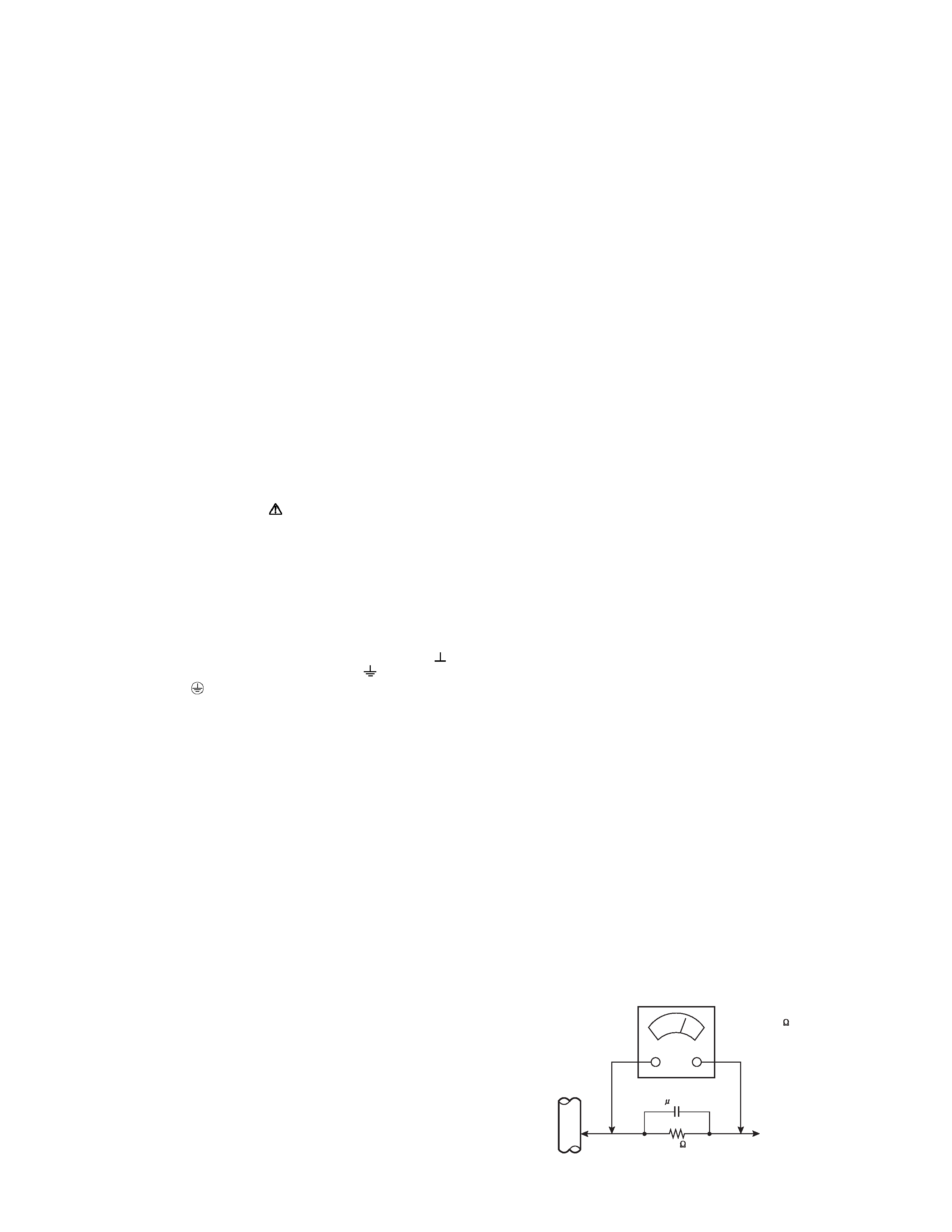
Alternate Check Method
Plug the AC line cord directly into the AC outlet (do not
use a line isolation transformer during this check.). Use
an AC voltmeter having 1000
per volt or more
sensitivity in the following manner. Connect a 1500
10W resistor paralleled by a 0.15
µF AC-type capacitor
between an exposed metal part and a known good earth
ground (water pipe, etc.). Measure the AC voltage
across the resistor with the AC voltmeter. Move the
resistor connection to each exposed metal part,
particularly any exposed metal part having a return path
to the chassis, and measure the AC voltage across the
resistor. Now, reverse the plug in the AC outlet and
repeat each measurement. Any voltage measured must
not exceed 0.75V AC (r.m.s.). This corresponds to
0.5mA AC (r.m.s.).
However, in tropical area, this must not exceed 0.3V AC
(r.m.s.). This corresponds to 0.2mA AC (r.m.s.).
AC VOLTMETER
(HAVING 1000 /V,
OR MORE SENSITIVITY)
PLACE THIS PROBE
ON EACH EXPOSED
METAL PART
1500
10W
0.15 F AC-TYPE
GOOD EARTH GROUND
1-4 (No.52122)
SECTION 2
SPECIFIC SERVICE INSTRUCTIONS
2.1
FEATURES
· New chassis design enables use of a main board with simplified circuitry.
· Provided with miniature tuner (TV/CATV).
· PLL synthesizer system TV/CATV totaling 181 channels.
· Multifunctional remote control permits picture adjustment.
· With NTSC/PAL-M/PAL-N colour/sound systems.
· Adoption of the VIDEO STATUS function.
·With 75
VHF/UHF in common (F-Type) antenna terminal.
· Wide range rated voltage (110V~240V) AC power input.
· Closed caption broadcasts can be viewed.
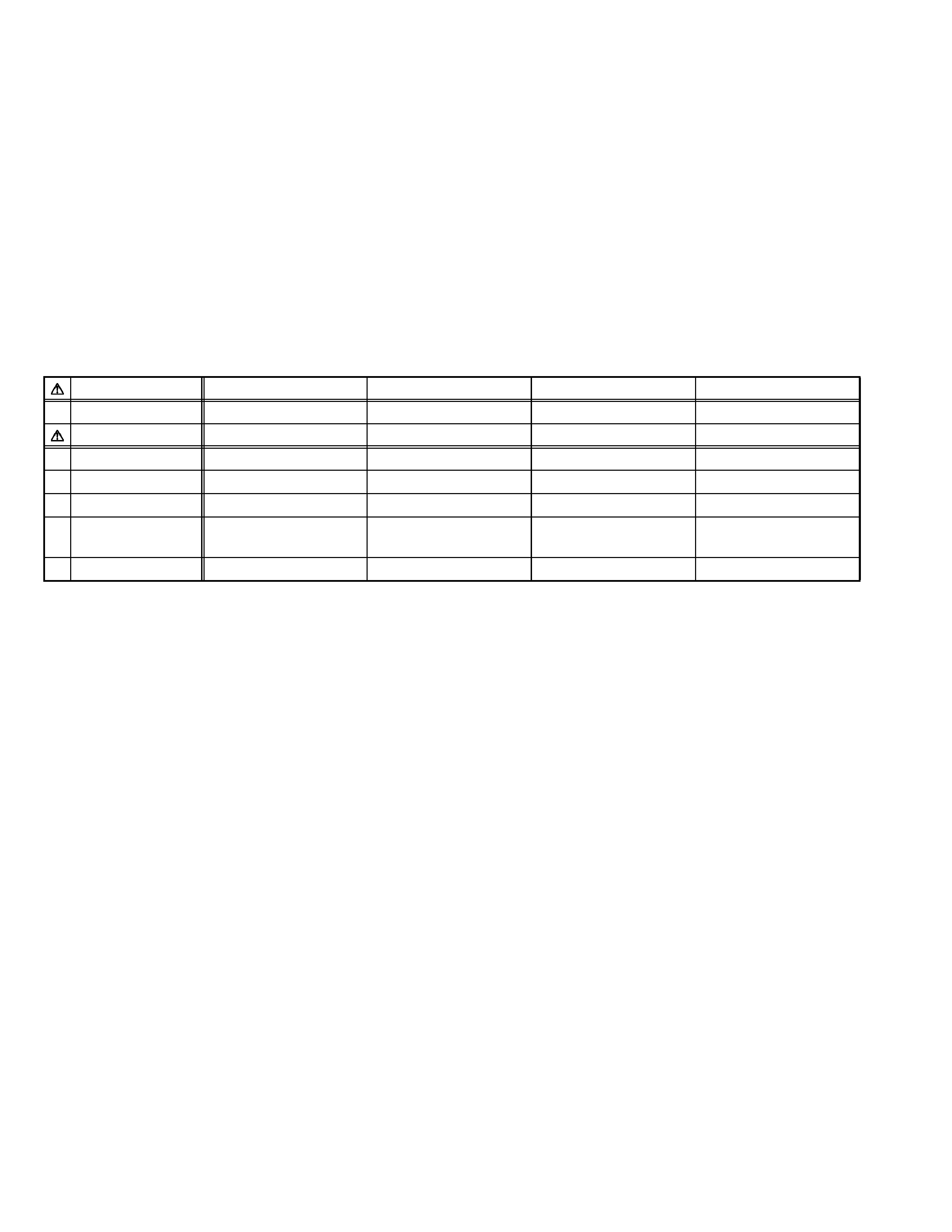
2.2
MAIN DIFFERENCE LIST
Item
AV-14FN11/P
AV-14FT11/P
AV-20NN11/P
AV-20NT11/P
MAIN PWB
SCJ-1002A-H2
SCJ-1008A-H2
SCJ-1007A-H2
SCJ-1001A-H2
PICTURE TUBE
A34KQW42X
A48LWX10X
Colour System
NTSC / PAL-M / PAL-N
NTSC / PAL-M / PAL-N
NTSC / PAL-M / PAL-N
NTSC / PAL-M / PAL-N
Sound System
---
BTSC (Multi Channel Sound)
---
BTSC (Multi Channel Sound)
Power Consumption 48W
52W
59W
62W
Speaker
5cm
× 9cm Oval type × 2
(monaural)
5cm
× 9cm Oval type × 2
(stereo)
5cm
× 12cm Oval type × 2
(monaural)
5cm
× 12cm Oval type × 2
(stereo)
Audio Power Output 3W (monaural)
3W + 3W (stereo)
3W (monaural)
3W+3W (stereo)

(No.52122)1-5
SECTION 3
DISASSEMBLY
3.1
DISASSEMBLY PROCEDURE [AV-14FN11 / AV-14FT11]
3.1.1 REMOVING THE REAR COVER
(1) Unplug the power plug.
(2) Remove the 4 screws [A], and 1 screw [B] as shown in
Fig.1.
(3) Remove the 2 screws [C] as shown in Fig.1.
(4) Withdraw the REAR COVER toward you.
CAUTION:
When reinstalling the rear cover, carefully push it inward after
inserting the MAIN PWB into the rear cover groove.
3.1.2 REMOVING THE MAIN PW BOARD
· Remove the REAR COVER.
(1) Slightly raise the both side of the MAIN PW BOARD by
hand, and remove the PWB STOPPER [D] from the front
cabinet.
(2) Withdraw the MAIN PWB backward.(If necessary, remove
the wire clamp and connectors, etc.)
3.1.3 REMOVING THE SPEAKER
· Remove the REAR COVER.
(1) Remove the 2 screws [E].
(2) Then you can remove the SPEAKER.
3.1.4 CHECKING THE MAIN PW BOARD
(1) Pull out the MAIN PW board. (Refer to REMOVING THE
MAIN PW Board)
(2) Erect the chassis vertically so that you can easily check the
MAIN PWB from the reverse (solder) side.
CAUTION:
· When erecting the MAIN PWB, be careful so that there will
be no contacting with other PWB.
· Before turning power on, make sure that the CRT earth wire
and other connectors are properly connected.
3.1.5 WIRE CLAMPING AND CABLE TYING
(1) Be sure to clamp the wire.
(2) Never remove the cable tie used for tying the wires
together. Should it be inadvertently removed, be sure to tie
the wires with a new cable tie.