No.51865
Nov. 2000
AV-14FR10/AV-14F10
AV-1434TEE/AV-1434EE
AV-14FTT2/AV-14FTG2
1
COPYRIGHT © 2001 VICTOR COMPANY OF JAPAN, LTD.
Nov. 2001
AV-14FR10/AV-14F10
AV-1434TEE/AV-1434EE
AV-14FTT2/AV-14FTG2/-A
CONTENTS
! SPECIFICATIONS
2
! SAFETY PRECAUTIONS
3
! FEATURES
4
! MAIN DIFFERENCE LIST
5
! FUNCTIONS
6
! SPECIFIC SERVICE INSTRUCTIONS
8
! SERVICE ADJUSTMENTS
15
! PARTS LIST
33
OPERATING INSTRUCTIONS
STANDARD CIRCUIT DIAGRAM
2-1
BASIC CHASSIS
CG
SERVICE MANUAL
COLOUR TELEVISION
[ RM-C364GY ]
[ RM-C90 ]
No. 51865
AV-14FR10/AV-14F10
AV-1434TEE/AV-1434EE
AV-14FTT2/AV-14FTG2
2
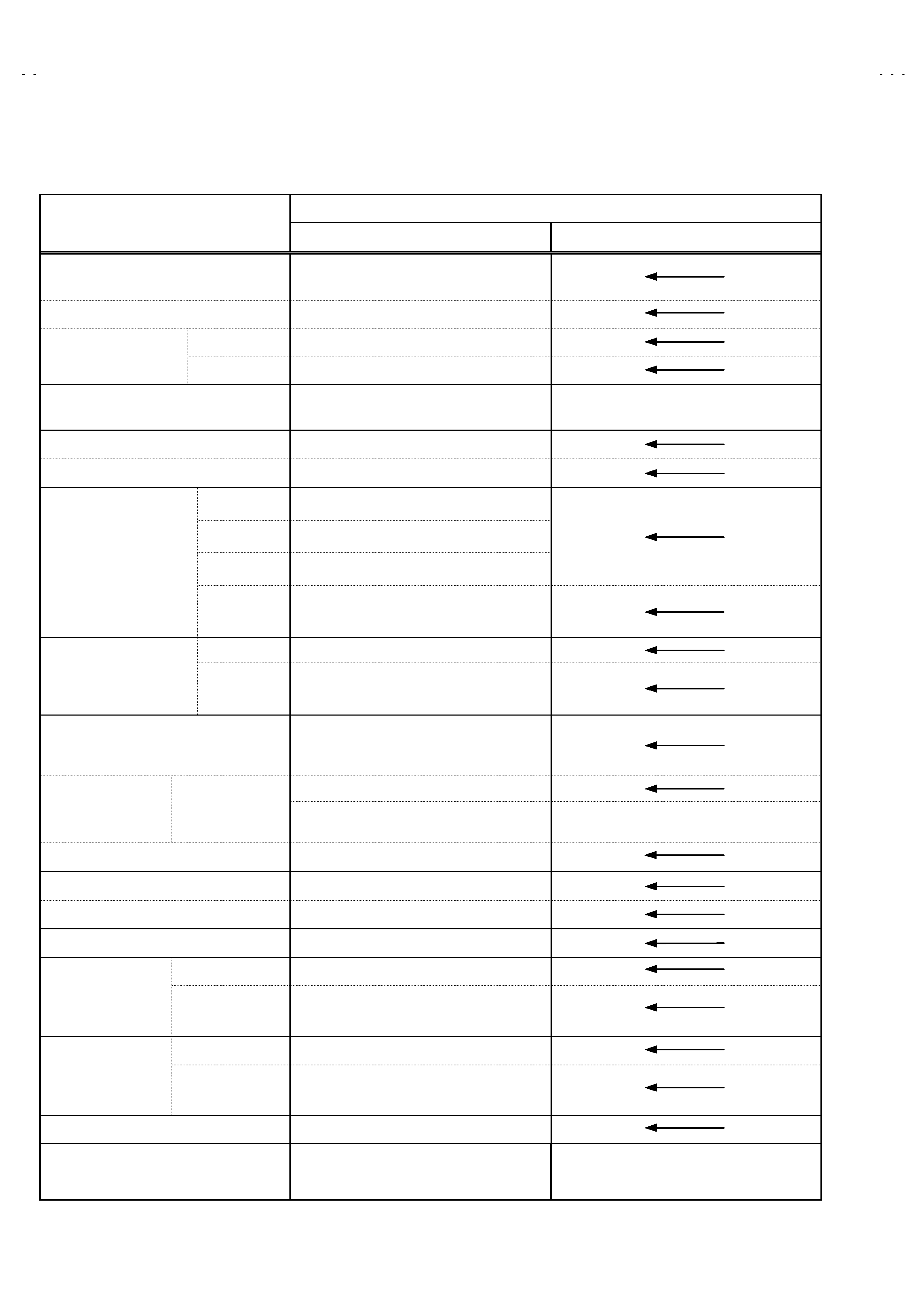
SPECIFICATIONS
CONTENT
ITEM
AV-14FR10 / AV-1434TEE / AV-14FTT2
AV-14F10 / AV-1434EE / AV-14FTG2/-A
Dimensions(W×H×D)
Mass
462mm×340.5mm×375mm
10kg
TV RF System
B/G, I, D/K, K1,
RF Mode
PAL / SECAM
Colour System
VIDEO Mode
PAL / SECAM / NTSC3.58 / NTSC4.43
Teletext System
FLOF (UK system )
WST (world standard system)
×
×
×
×
Picture Tube
Visible size: 34cm measured diagonally
High Voltage
22.5kV±1.5kV(at zero beam current)
Receiving Frequency
VHF (VL)
43.75MHz155.75MHz
VHF (VH)
155.78MHz466.25MHz
UHF
466.28MHz864.75MHz
CATV
Cable TVs of Mid (X-Z, S1-S10)
Super (S11-S20) & Hyper (S21-S41)
bands receivable
VIF Carrier
38.0MHz
Intermediate
Frequency
SIF Carrier
32.5MHz(5.5MHz)
31.5MHz (6.5MHz)
32.0MHz (6.0MHz)
Colour Sub Carrier Frequency
PAL (4.43MHz),
SECAM (4.40625MHz / 4.25MHz)
NTSC (3.58MHz / 4.43MHz)
AC220240V, 50 / 60Hz
Power Input
Rated Voltage
AC110240V, 50 / 60Hz
[ Only AV-14FTT2 ]
AC110240V, 50 / 60Hz
[ Only AV-14FTG2/-A ]
Power Consumption
68W (Max) / 47W(Avg.)
Speaker
5cm×9cm, Oval type×2
Audio Output
2W (monaural)
Aerial Input Terminal
75 Unbalanced
Input
Video
1V(p-p), 75, RCA×2 (Front / Rear)
Audio
500mV(rms) (-4dBs), High impedance,
RCA×2 (Front / Rear)
Output
Video
1V(p-p), 75, RCA×1
Audio
500mV(rms) (-4dBs), Low impedance,
RCA×1
Headphone jack
3.5mm mini jack
Remote Control Unit
RM-C90
(Battery size : AA / R06 / UM-3×2)
RM-C364GY
(Battery size : AA / R06 / UN-3×2)
Design and specifications are subject to change without notice.
No.51865
AV-14FR10/AV-14F10
AV-1434TEE/AV-1434EE
AV-14FTT2/AV-14FTG2
3
SAFETY PRECAUTIONS
1.
The design of this product contains special hardware, many
circuits and components specially for safety purposes. For
continued protection, no changes should be made to the original
design unless authorized in writing by the manufacturer.
Replacement parts must be identical to those used in the original
circuits. Service should be performed by qualified personnel
only.
2.
Alterations of the design or circuitry of the products should not be
made. Any design alterations or additions will void the
manufacturer's warranty and will further relieve the manufacturer
of responsibility for personal injury or property damage resulting
therefrom.
3.
Many electrical and mechanical parts in the products have
special safety-related characteristics. These characteristics are
often not evident from visual inspection nor can the protection
afforded by them necessarily be obtained by using replacement
components rated for higher voltage, wattage, etc. Replacement
parts which have these special safety characteristics are
identified in the parts list of Service manual. Electrical
components having such features are identified by shading
on the schematics and by (!
!
!
!) on the parts list in Service
manual. The use of a substitute replacement which does not
have the same safety characteristics as the recommended
replacement part shown in the parts list of Service manual may
cause shock, fire, or other hazards.
4.
Don't short between the LIVE side ground and ISOLATED
(NEUTRAL) side ground or EARTH side ground when
repairing.
Some model's power circuit is partly different in the GND. The
difference of the GND is shown by the LIVE : (") side GND, the
ISOLATED(NEUTRAL) : (#) side GND and EARTH : ($) side
GND.
Don't
short
between
the
LIVE
side
GND
and
ISOLATED(NEUTRAL) side GND or EARTH side GND and
never measure with a measuring apparatus (oscilloscope etc.)
the LIVE side GND and ISOLATED(NEUTRAL) side GND or
EARTH side GND at the same time.
If above note will not be kept, a fuse or any parts will be broken.
5.
If any repair has been made to the chassis, it is recommended
that the B1 setting should be checked or adjusted (See
ADJUSTMENT OF B1 POWER SUPPLY).
6.
The high voltage applied to the picture tube must conform with
that specified in Service manual. Excessive high voltage can
cause an increase in X-Ray emission, arcing and possible
component damage, therefore operation under excessive high
voltage conditions should be kept to a minimum, or should be
prevented. If severe arcing occurs, remove the AC power
immediately and determine the cause by visual inspection
(incorrect installation, cracked or melted high voltage harness,
poor soldering, etc.). To maintain the proper minimum level of
soft X-Ray emission, components in the high voltage circuitry
including the picture tube must be the exact replacements or
alternatives approved by the manufacturer of the complete
product.
7.
Do not check high voltage by drawing an arc. Use a high voltage
meter or a high voltage probe with a VTVM. Discharge the
picture tube before attempting meter connection, by connecting
a clip lead to the ground frame and connecting the other end of
the lead through a 10k
! 2W resistor to the anode button.
8.
When service is required, observe the original lead dress. Extra
precaution should be given to assure correct lead dress in the
high voltage circuit area. Where a short circuit has occurred,
those components that indicate evidence of overheating should
be replaced. Always use the manufacturer's replacement
components.
9.
Isolation Check
(Safety for Electrical Shock Hazard)
After re-assembling the product, always perform an isolation
check on the exposed metal parts of the cabinet (antenna
terminals, video/audio input and output terminals, Control knobs,
metal cabinet, screwheads, earphone jack, control shafts, etc.)
to be sure the product is safe to operate without danger of
electrical shock.
(1) Dielectric Strength Test
The isolation between the AC primary circuit and all metal parts
exposed to the user, particularly any exposed metal part having a
return path to the chassis should withstand a voltage of 3000V
AC (r.m.s.) for a period of one second.
(. . . . Withstand a voltage of 1100V AC (r.m.s.) to an appliance
rated up to 120V, and 3000V AC (r.m.s.) to an appliance rated
200V or more, for a period of one second.)
This method of test requires a test equipment not generally found
in the service trade.
(2) Leakage Current Check
Plug the AC line cord directly into the AC outlet (do not use a line
isolation transformer during this check.). Using a "Leakage
Current Tester", measure the leakage current from each exposed
metal part of the cabinet, particularly any exposed metal part
having a return path to the chassis, to a known good earth
ground (water pipe, etc.). Any leakage current must not exceed
0.5mA AC (r.m.s.).
However, in tropical area, this must not exceed 0.2mA AC
(r.m.s.).
"
"
"
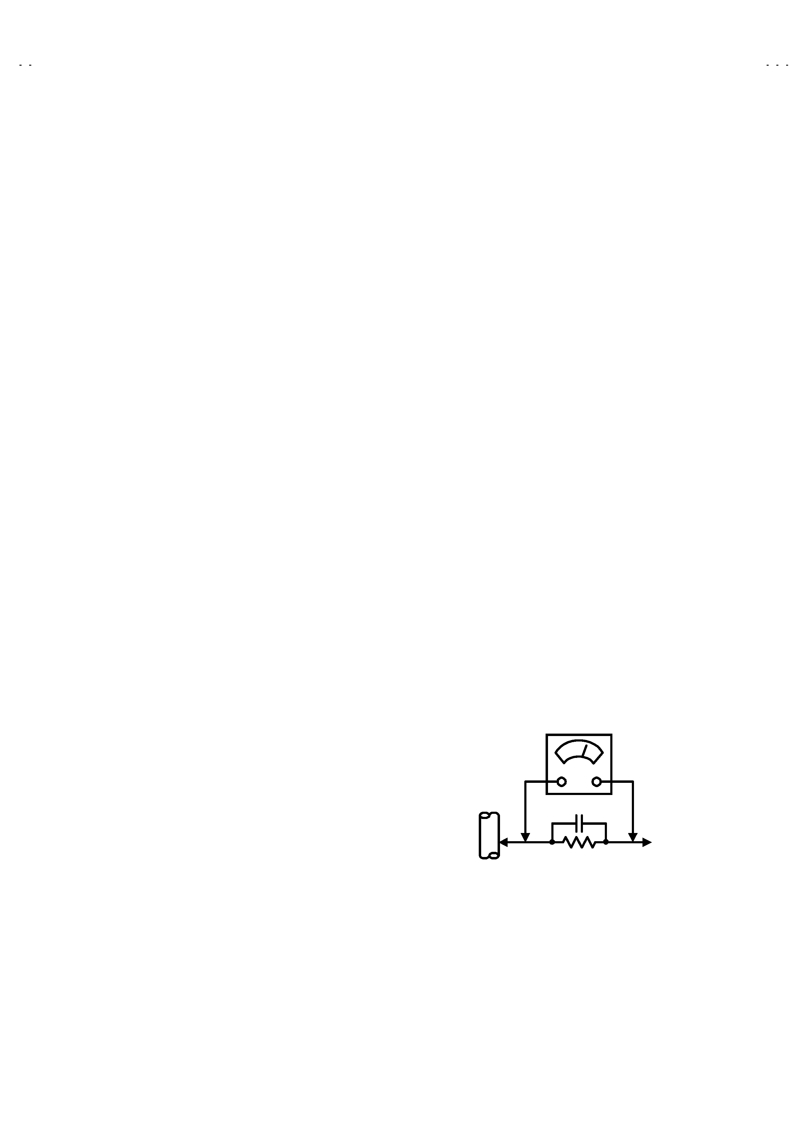
" Alternate Check Method
Plug the AC line cord directly into the AC outlet (do not use a line
isolation transformer during this check.). Use an AC voltmeter
having 1000 ohms per volt or more sensitivity in the following
manner. Connect a 1500
! 10W resistor paralleled by a 0.15"F
AC-type capacitor between an exposed metal part and a known
good earth ground (water pipe, etc.). Measure the AC voltage
across the resistor with the AC voltmeter. Move the resistor
connection to each exposed metal part, particularly any exposed
metal part having a return path to the chassis, and measure the
AC voltage across the resistor. Now, reverse the plug in the AC
outlet and repeat each measurement. Any voltage measured
must not exceed 0.75V AC (r.m.s.).
This corresponds to 0.5mA
AC (r.m.s.).
However, in tropical area, this must not exceed 0.3V AC (r.m.s.).
This corresponds to 0.2mA AC (r.m.s.).
0.15F AC-TYPE
1500
! 10W
GOOD EARTH GROUND
PLACE THIS PROBE
ON EACH EXPOSED
METAL PART
AC VOLTMETER
(HAVING 1000
!/V,
OR MORE SENSITIVITY)
No. 51865
AV-14FR10/AV-14F10
AV-1434TEE/AV-1434EE
AV-14FTT2/AV-14FTG2
4
FEATURES
! New chassis design enables use of an interactive on-screen control.
! Wide range voltage (110V240V) AC power input (AV-14FTT2 / AV-14FTG2/-A)
! With AUDIO / VIDEO INPUT & OUTPUT terminal.
! MUTING button can reduce the audio level to zero instantly.
! Functional remote control to operate TV set (for channel select, volume control, power ON/OFF, etc.) from a distance.
! I2C bus control utilizes single chip ICs for IF, V/C, DEF. VSM PRESET, PRESET & TURBO TIMER.
! By means of AUTO PROGRAM, the TV stations can be selected automatically and the TV channels can also be rearranged automatically.
! The TELETEXT SYSTEM has a built-in FASTEXT / WST system (for AV-14FR10 / AV-1434TEE / AV-14FTT2)
! Built-in ECO MODE (ECONOMY, ECOLOGY)
In accordance with the brightness in a room, the brightness and / of contrast of the picture can be adjusted automatically to make the
optimum picture which is easy on the eye.
! Built-in ON TIMER, RETURN + & CHILD LOCK.
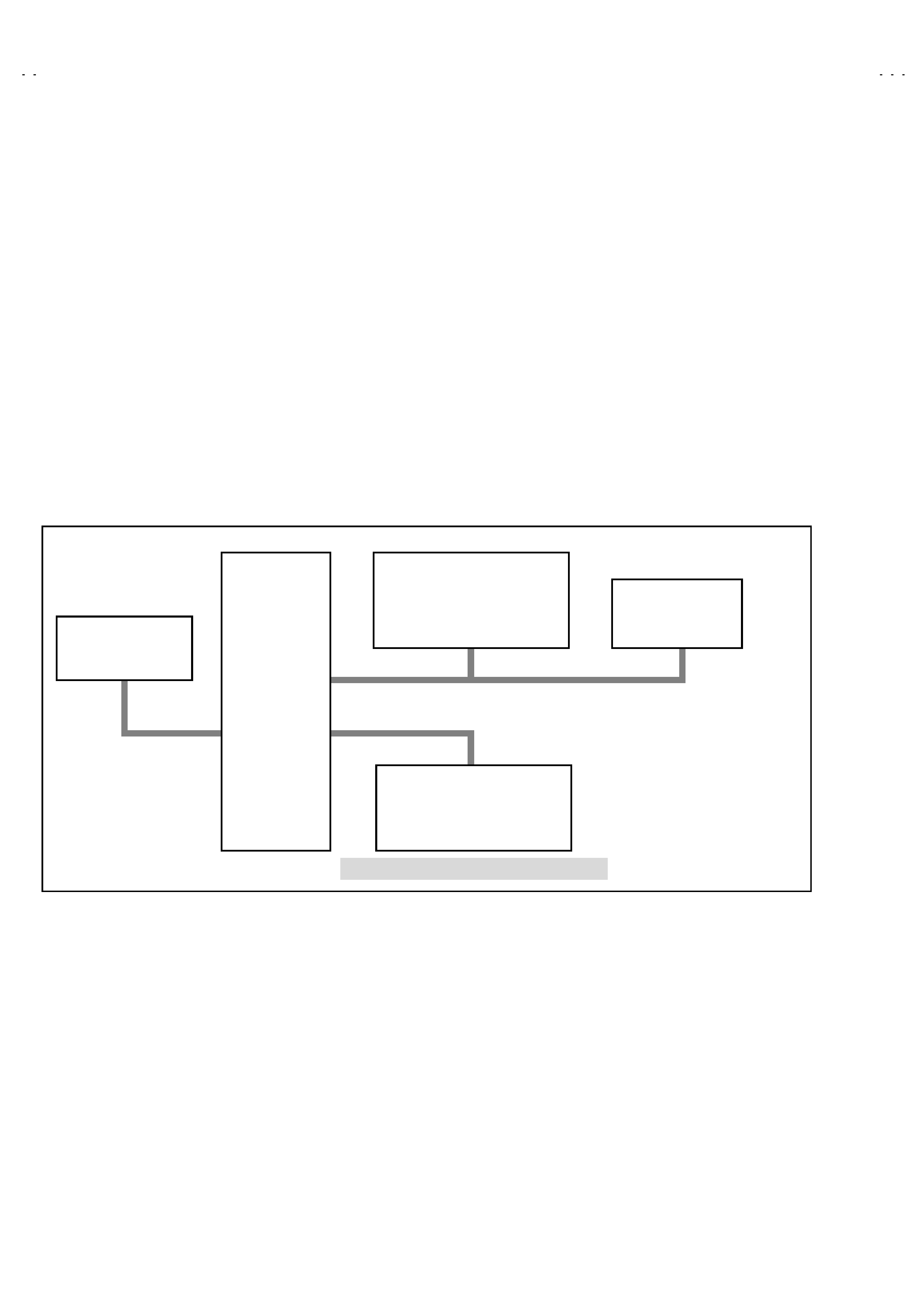
SYSTEM BLOCK DIAGRAM
IC301
VIDEO/CHROMA
DECORDER
IC702
MEMORY
TU001
TUNER
IC701
MICRO
COMPUTER
IC821
TEXT DECORDER
SCL1/SDA1
SCL2/SDA2
TCL/TDA
(for AV-14FR10 / AV-1434TEE / AV-14FTT2)
No. 51865
AV-14FR10/AV-14F10
AV-1434TEE/AV-1434EE
AV-14FTT2/AV-14FTG2
5
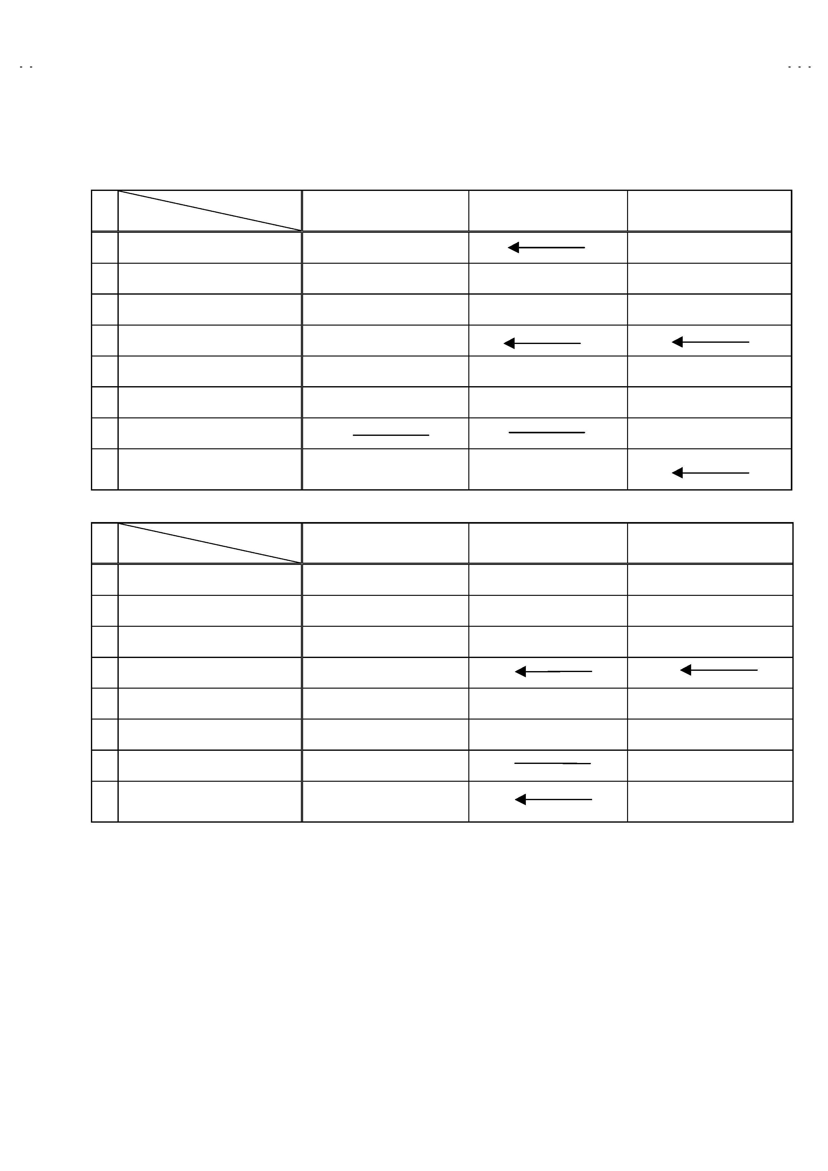
MAIN DIFFERENCE LIST
!
Model Name
Part Name
AV-14FR10
AV-1434TEE
AV-14FTT2
MAIN PWB
SCG-1289A-H2
SCG-1290A-H2
!
FRONT CABINET
LC10831-013A-H
LC10831-018A-H
LC10831-017A-H
PACKING CASE
GG10056-059A-H
GG10056-060A-H
GG10056-058A-H
REMOTE CONTROL UNIT
RM-C90-1H
!
RATING LABEL
GG20014-002A-H
GG20014-005A-H
LC20377-001B-H
!
INST. BOOK
LCT1028-001A-H
LCT1029-001A-H
LCT0990-001B-H
!
DIGEST MANUAL
LCT0992-001B-H
!
POWER CORD
QMPR340-165-K2
QMP40D0-200J5
or QMP40D0-200J3
!
Model Name
Part Name
AV-14F10
AV-1434EE
AV-14FTG2/-A
MAIN PWB
SCG-1285A-H2
SCG-1286A-H2
SCG-1024A-H2
!
FRONT CABINET
LC10831-014A-H
LC10831-015A-H
LC10831-012A-H
PACKING CASE
GG10056-047A-H
GG10056-045A-H
LC10845-027A-H
REMOTE CONTROL UNIT
RM-C364GY-1H
!
RATING LABEL
GG20014-002A-H
GG20014-005A-H
LC20413-002B-H
!
INST. BOOK
LCT1039-001A-H
LCT1029-001A-H
LCT0994-001B-H
!
DIGEST MANUAL
LCT1034-001A-H
LCT0993-001B-H
!
POWER CORD
QMP40D0-200J5
or QMP40D0-200J3
QMPR010-200-E2
or QMPR010-200-K2