SERVICE MANUAL
No.86592
November 2000
AA-V40EG/EK
SPECIFICATIONS
AC POWER ADAPTER/CHARGER
This service manual is made from all recycled paper.
COPYRIGHT © 2000 VICTOR COMPANY OF JAPAN, LTD
Power
Power
consumption
Output
Operating
temperature
Charging
temperature
Dimensions
Weight
AC 110 V -- 240 V,
50 Hz/60 Hz
23 W
DC 7.2 V
, 1.2 A
(When charging)
DC 6.3 V
, 1.8 A
(When supplying power)
0
°C -- 40°C
10
°C -- 35°C
68 (W) x 38 (H) x 110 (D) mm
AA-V40EG : Approx. 260 g
AA-V40EK : Approx. 340 g
Important Safety Precautions
Prior to shipment from the factory, JVC products are strictly inspected to conform with the recognized product safety and electrical codes
of the countries in which they are to be sold. However, in order to maintain such compliance, it is equally important to implement the
following precautions when a set is being serviced.
Fig.1
1. Locations requiring special caution are denoted by labels and
inscriptions on the cabinet, chassis and certain parts of the
product. When performing service, be sure to read and com-
ply with these and other cautionary notices appearing in the
operation and service manuals.
2. Parts identified by the
symbol and shaded (
) parts are
critical for safety.
Replace only with specified part numbers.
Note: Parts in this category also include those specified to com-
ply with X-ray emission standards for products using
cathode ray tubes and those specified for compliance
with various regulations regarding spurious radiation
emission.
3. Fuse replacement caution notice.
Caution for continued protection against fire hazard.
Replace only with same type and rated fuse(s) as specified.
4. Use specified internal wiring. Note especially:
1) Wires covered with PVC tubing
2) Double insulated wires
3) High voltage leads
5. Use specified insulating materials for hazardous live parts.
Note especially:
1) Insulation Tape
3) Spacers
5) Barrier
2) PVC tubing
4) Insulation sheets for transistors
6. When replacing AC primary side components (transformers,
power cords, noise blocking capacitors, etc.) wrap ends of
wires securely about the terminals before soldering.
Power cord
Fig.2
10. Also check areas surrounding repaired locations.
11. Products using cathode ray tubes (CRTs)
In regard to such products, the cathode ray tubes themselves,
the high voltage circuits, and related circuits are specified for
compliance with recognized codes pertaining to X-ray emission.
Consequently, when servicing these products, replace the cath-
ode ray tubes and other parts with only the specified parts.
Under no circumstances attempt to modify these circuits.
Unauthorized modification can increase the high voltage value
and cause X-ray emission from the cathode ray tube.
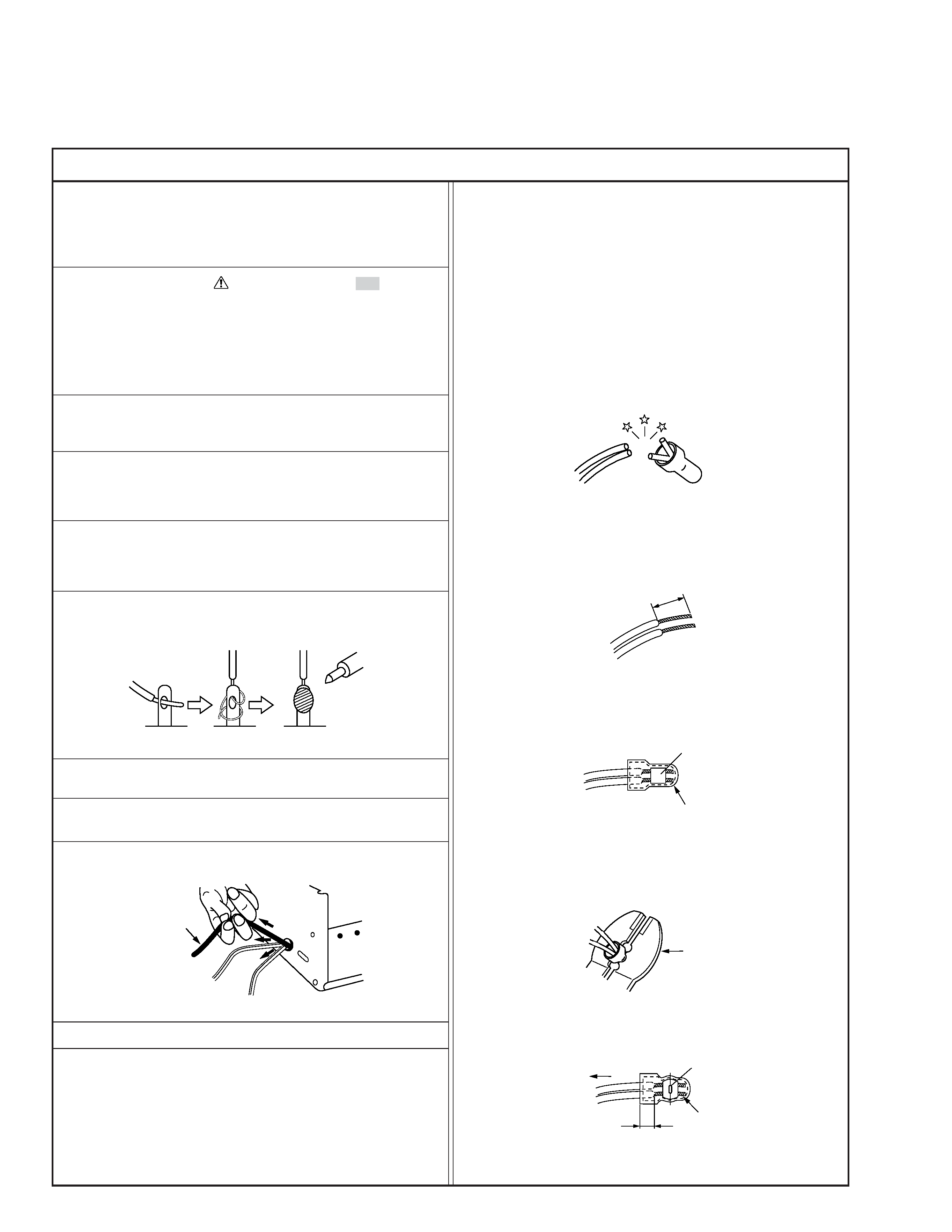
12. Crimp type wire connector
In such cases as when replacing the power transformer in sets
where the connections between the power cord and power
transformer primary lead wires are performed using crimp type
connectors, if replacing the connectors is unavoidable, in or-
der to prevent safety hazards, perform carefully and precisely
according to the following steps.
1) Connector part number : E03830-001
2) Required tool : Connector crimping tool of the proper type
which will not damage insulated parts.
3) Replacement procedure
(1) Remove the old connector by cutting the wires at a point
close to the connector.
Important : Do not reuse a connector (discard it).
Fig.7
cut close to connector
Fig.3
(2) Strip about 15 mm of the insulation from the ends of
the wires. If the wires are stranded, twist the strands to
avoid frayed conductors.
15 mm
Fig.4
(3) Align the lengths of the wires to be connected. Insert
the wires fully into the connector.
Connector
Metal sleeve
Fig.5
(4) As shown in Fig.6, use the crimping tool to crimp the
metal sleeve at the center position. Be sure to crimp fully
to the complete closure of the tool.
1
Precautions during Servicing
7. Observe that wires do not contact heat producing parts
(heatsinks, oxide metal film resistors, fusible resistors, etc.)
8. Check that replaced wires do not contact sharp edged or
pointed parts.
9. When a power cord has been replaced, check that 10-15 kg of
force in any direction will not loosen it.
1.25
2.0
5.5
Crimping tool
Fig.6
(5) Check the four points noted in Fig.7.
Not easily pulled free
Crimped at approx. center
of metal sleeve
Conductors extended
Wire insulation recessed
more than 4 mm
S40888-01
Safety Check after Servicing
Examine the area surrounding the repaired location for damage or deterioration. Observe that screws, parts and wires have been
returned to original positions, Afterwards, perform the following tests and confirm the specified values in order to verify compli-
ance with safety standards.
1. Insulation resistance test
Confirm the specified insulation resistance or greater between power cord plug prongs and
externally exposed parts of the set (RF terminals, antenna terminals, video and audio input
and output terminals, microphone jacks, earphone jacks, etc.). See table 1 below.
2. Dielectric strength test
Confirm specified dielectric strength or greater between power cord plug prongs and exposed
accessible parts of the set (RF terminals, antenna terminals, video and audio input and output
terminals, microphone jacks, earphone jacks, etc.). See table 1 below.
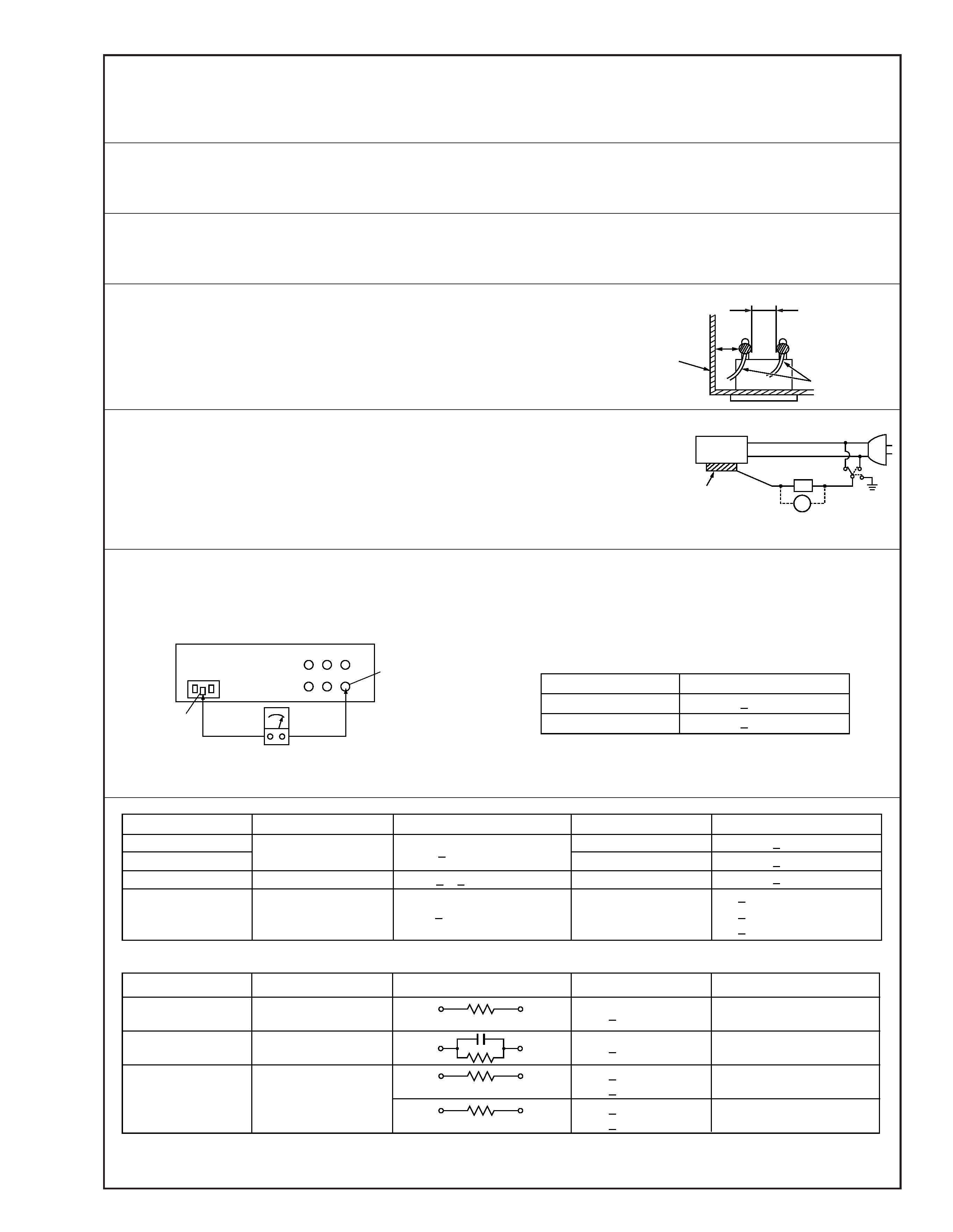
3. Clearance distance
When replacing primary circuit components, confirm specified clearance distance (d), (d') be-
tween soldered terminals, and between terminals and surrounding metallic parts. See table 1
below.
4. Leakage current test
Confirm specified or lower leakage current between earth ground/power cord plug prongs
and externally exposed accessible parts (RF terminals, antenna terminals, video and audio
input and output terminals, microphone jacks, earphone jacks, etc.).
Measuring Method : (Power ON)
Insert load Z between earth ground/power cord plug prongs and externally exposed accessi-
ble parts. Use an AC voltmeter to measure across both terminals of load Z. See figure 9 and
following table 2.
5. Grounding (Class 1 model only)
Confirm specified or lower grounding impedance between earth pin in AC inlet and externally exposed accessible parts (Video in,
Video out, Audio in, Audio out or Fixing screw etc.).
Measuring Method:
Connect milli ohm meter between earth pin in AC inlet and exposed accessible parts. See figure 10 and grounding specifications.
d'
d
Chassis
Power cord,
primary wire
Region
USA & Canada
Europe & Australia
Grounding Impedance (Z)
Z
0.1 ohm
Z
0.5 ohm
AC inlet
Earth pin
Exposed accessible part
Milli ohm meter
Grounding Specifications
Fig. 10
ab
c
V
Externally
exposed
accessible part
Z
Fig. 9
Fig. 8
Clearance Distance (d), (d')
d, d'
3 mm
d, d'
4 mm
d, d'
3.2 mm
1 M
R 12 M/500 V DC
Dielectric Strength
AC 1 kV 1 minute
AC 1.5 kV 1 miute
AC 1 kV 1 minute
AC Line Voltage
100 V
100 to 240 V
110 to 130 V
110 to 130 V
200 to 240 V
Japan
USA & Canada
Europe & Australia
R
10 M
/500 V DC
Region
Insulation Resistance (R)
R
1 M
/500 V DC
AC 3 kV 1 minute
(Class
2)
AC 1.5 kV 1 minute
(Class
1)
d
4 mm
d'
8 mm (Power cord)
d'
6 mm (Primary wire)
Table 1 Specifications for each region
a, b, c
Leakage Current (i)
AC Line Voltage
100 V
110 to 130 V
110 to 130 V
220 to 240 V
Japan
USA & Canada
i
1 mA rms
Exposed accessible parts
Exposed accessible parts
Antenna earth terminals
Other terminals
i
0.5 mA rms
i
0.7 mA peak
i
2 mA dc
i
0.7 mA peak
i
2 mA dc
Europe & Australia
Region
Load Z
1k
2k
1.5 k
0.15 µF
50 k
Table 2 Leakage current specifications for each region
Note: These tables are unofficial and for reference only. Be sure to confirm the precise values for your particular country and locality.
2
S40888-01
EN-2
T
hank
y
ou
for
pur
chasing
the
JVC
A
C
P
o
wer
Adapter/Charger
.T
his
unit
pro
vides
DC
po
wer
for
the
JVC
Digital
V
ideo
Camer
afrom
a
household
A
C
outlet.
It
can
be
used
to
rec
harge
the
JVC
battery
pac
kfor
exclusi
ve
use
with
the
JVC
Digital
V
ideo
Camer
a,
and
is
capable
of
c
harging
tw
o
battery
pac
ks
consecuti
vely
.T
o
a
void
problems
and
obtain
the
best
results,
please
read
this
instruction
booklet
carefully
before
use.
Before
using
as
a
po
wer
adapter
,make
sure
that
this
unit'
smodel
number
is
the
same
as
that
of
the
po
wer
supply
unit
specified
in
the
instruction
manual
of
the
equipment
y
ou
wish
to
po
wer
.
W
ARNING:
TO
PREVENT
FIRE
OR
SHOCK
HAZARD,
DO
NOT
EXPOSE
THIS
UNIT
TO
RAIN
OR
MOISTURE.
This
unit
should
be
used
with
A
C
110
V
240
V
`````
,
50
Hz/60
Hz
onl
y.
CAUTION:
To
pr
ev
ent
electric
shoc
ks
and
fire
hazards,
do
NOT
use
any
other
power
source.
When
the
equipment
is
installed
in
a
cabinet
or
on
a
shelf,
make
sure
that
it
has
sufficient
space
on
all
sides
to
allow
for
ventilation
(10
cm
or
more
on
both
sides,
on
top
and
at
the
rear).
Do
not
block
the
ventilation
holes.
(If
the
ventilation
holes
are
blocked
by
a
newspaper
,or
cloth
etc.
the
heat
ma
ynot
be
able
to
get
out.)
No
naked
flame
sources,
suc
h
as
lighted
candles,
should
be
placed
on
the
apparatus.
When
discarding
batteries,
environmental
problems
must
be
considered
and
the
local
rules
or
laws
governing
the
disposal
of
these
batteries
must
be
followed
strictly
.
The
apparatus
shall
not
be
exposed
to
dripping
or
splashing.
Do
not
use
this
equipment
in
a
bathroom
or
places
with
w
ater
.
Also
do
not
place
any
containers
filled
with
water
or
liquids
(such
as
cosmetics
or
medicines,
flower
vases,
potted
plants,
cups
etc.)
on
top
of
this
unit.
(If
water
or
liquid
is
allowed
to
enter
this
equipment,
fire
or
electric
shock
may
be
caused.)
NOTE:
The
rating
plate
(Serial
number
plate)
is
on
the
bottom
of
the
unit.
CAUTION:
To
prev
ent
electric
shock,
do
not
open
the
cabinet.
No
user
serviceable
parts
inside.
Refer
servicing
to
qualified
service
personnel.
CAUTION:
When
you
are
not
using
this
unit
for
a
long
period
of
time,
it
is
recommended
that
you
disconnect
the
power
cord
from
A
C
outlet.
W
ARNING--
DANGEROUS
V
O
LT
A
GE
INSIDE
EN-3
IMPOR
TANT
Connection
to
the
mains
supply
in
the
United
Kingdom.
DO
NO
T
cut
off
the
mains
plug
fr
om
this
equipment.
If
the
plug
fitted
is
not
suitable
for
the
power
points
in
your
home
or
the
cable
is
too
short
to
reach
a
power
point,
then
obtain
an
appropriate
safety
approved
extension
lead
or
consult
y
our
dealer
.
BE
SURE
to
replace
the
fuse
only
with
an
identical
approved
type,
as
originally
fitted,
and
to
replace
the
fuse
co
ve
r.
If
nonetheless
the
mains
plug
is
cut
off
ensure
to
remo
ve
the
fuse
and
dispose
of
the
plug
immediately
,
to
avoid
a
possible
shock
hazard
by
inadvertent
connection
to
the
mains
supply
.
If
this
product
is
not
supplied
fitted
with
a
mains
plug
then
follow
the
instructions
given
below:
DO
NO
T
make
an
yconnection
to
the
Larger
Terminal
coded
E
or
Green.
The
wires
in
the
mains
lead
are
coloured
in
accordance
with
the
following
code:
Blue
to
N
(Neutral)
or
Black
Brown
to
L
(Live)
or
Red
If
these
colours
do
not
correspond
with
the
terminal
identifications
of
your
plug,
connect
as
follows:
Blue
wire
to
terminal
coded
N
(Neutral)
or
coloured
black.
Brown
wire
to
terminal
coded
L
(Live)
or
coloured
Red.
If
in
doubt
--
consult
a
competent
electrician.
T
his
A
C
P
o
wer
Adapter/Charger
is
for
use
exclusively
with
JVC
Digital
Camcorders.
A
W
ORD
ON
THE
EXCLUSIVE
B
A
TTER
Y
P
A
CKS
The
battery
packs
are
lithium-ion.
Give
attention
to
the
following
to
make
the
most
of
their
characteristics.
For
c
harging:
10°C
to
35°C
For
operating:
0°C
to
40°C
For
storing:
10°C
to
30°C
CAUTIONS:
·
If
used
near
a
radio,
this
unit
may
interfere
with
reception.
·
Prevent
inflammables,
water
and
metallic
objects
from
entering
the
unit.
·
Do
not
disassemble
or
modify
the
unit.
·
Do
not
apply
shocks
to
the
unit.
·
Do
not
subject
the
unit
to
direct
sunlight.
·
A
void
using
the
unit
in
extremely
hot
or
humid
places.
·
A
void
using
the
unit
in
places
subject
to
vibrations.
EN-4
CHARGING
THE
BA
TTER
YPACK
POWER
indicator
CHARGE
indicator
DC
OUT
connector
AC
Power
Adapter/Charger
To
A
C
outlet
Battery
pack
BN-V408U,
BN-V416U
or
BN-V428U
A
A
-V40E
G
/E
K
INSTRUCTIONS
LYT0619-001A
BEDIENUNGSANLEITUNG
MANUEL
D'INSTRUCTIONS
GEBRUIKSAANWIJZING
MANUAL
DE
INSTRUCCIONES
MANUALE
DI
INSTRUZIONI
INSTRUKTIOSNBOG
KÄYTTÖOHJEET
BRUKSANVISNING
BRUKSANVISNING
AC
POWER
ADAPTER/CHARGER
NETZ-/LADEGERÄT
NÄTTILLSATS/BATTERILADDARE
ADAPTATEUR
SECTEUR/CHARGEUR
DE
BATTERIE
AC-ADAPTER/BATTERILADER
NETADAPTER/ACCULADER
ADAPTADOR/CARGADOR
DE
CA
ALIMENTATORE
CA/CARICABATTERIE
LYSNETADAPTER/OPLADER
VERKKOLAITE/AKUN
LATAAJA
DEUTSCH
FRANÇAIS
NEDERLANDS
CASTELLANO
IT
ALIANO
DANSK
SUOMI
SVENSKA
NORSK
CESTINA
POLSKI
MAGY
AR
ENGLISH
EN-5
NOTE:
Perform
c
harging
w
here
the
temper
ature
is
between
10°C
and
35°C.
20°C
to
25°C
is
the
ideal
temper
ature
r
ange
for
c
harging.
If
the
en
vironment
is
too
cold,
c
harging
ma
ybe
incomplete.
*
When
c
harged
at
temper
atures
between
20°C
and
25°C.
·
When
c
harging
Battery
P
ac
ks
after
a
long
stor
age
period,
c
harging
time
will
be
longer
than
the
time
indicated
above.
1
Plug
the
A
C
Adapter/Charger'
spo
wer
cord
into
an
A
C
outlet.
The
PO
WER
indicator
lights.
2
Remo
ve
the
battery
pac
k'
sprotecti
ve
cap.
Attach
the
battery
pack
with
the
mark
aligned
with
the
corresponding
marks
on
the
A
C
Po
wer
Adapter/Charger
.T
he
CHARGE
Indicator
begins
blinking
to
indicate
c
harging
has
started.
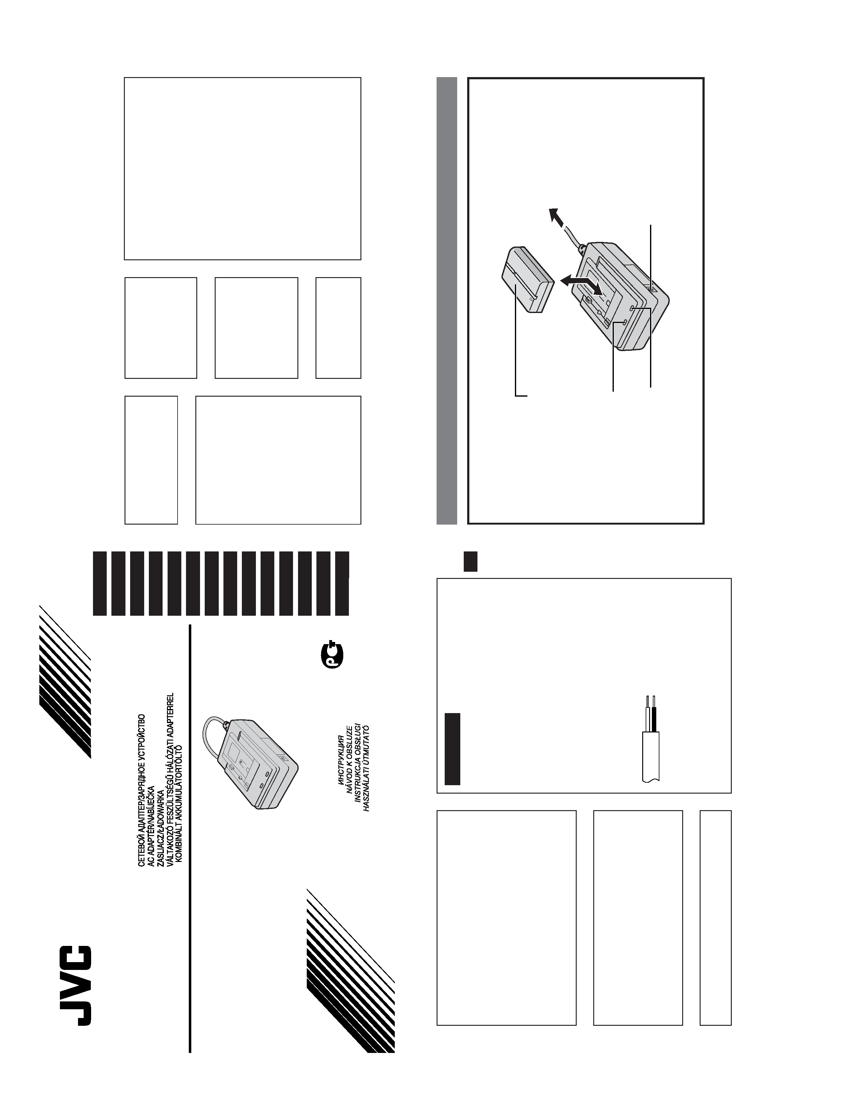
3
When
the
CHARGE
indicator
stops
blinking
but
sta
ys
lit,
c
harging
is
finished.
Slide
the
battery
and
lift
off.
Remember
to
unplug
the
A
C
Adapter/Charger'
spo
wer
cord
from
the
A
C
outlet.
Battery
pack
BN-V408U
BN-V416U
(optional)
BN-V428U
(optional)
Fully
charging
time
approx.
1
hr
.30
min.*
approx.
2
hrs.*
approx.
3
hrs.
20
min.*
EN-6
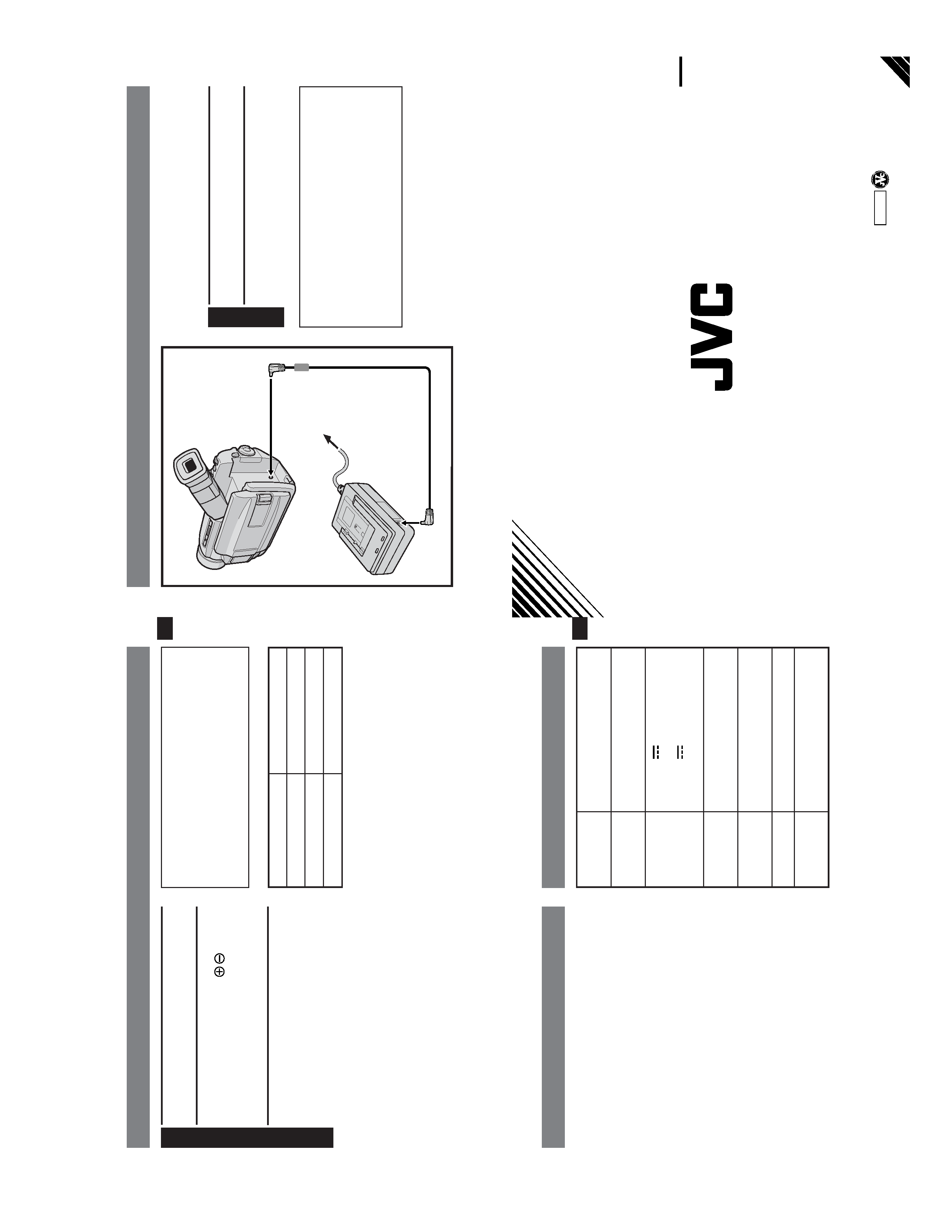
SUPPL
YING
POWER
You
can
connect
the
camcorder
to
an
A
C
outlet
using
the
A
C
P
o
wer
Adapter/Charger
(if
the
camcorder
is
supplied
with
a
DC
cord).
1
Plug
the
A
C
Adapter/Charger'
spo
wer
cord
into
an
A
C
outlet.
2
Connect
the
A
C
Adapter
to
the
camcorder
.
NOTES:
Be
sure
to
use
the
DC
cord
provided
with
your
camcorder
.
When
using
the
provided
DC
cord,
make
sure
you
connect
the
end
of
the
cable
with
the
core
filter
to
the
camcorder
.T
he
core
filter
improves
performance
of
equipment.
To
A
C
outlet
AC
Power
Adapter/Charger
Power
cord
To
DC
Input
connector
To
DC
OUT
connector
DC
cord
EN-7
T
he
A
C
P
o
wer
Adapter/Charger
is
specifically
designed
to
c
harge
BN-V408U,
BN-V416U
and/
or
BN-V428U
Battery
Packs.
When
c
harging
a
br
and
new
Battery
P
ac
k,
or
one
that'
sbeen
in
stor
age
for
an
extended
period,
the
Charging
Indicator
ma
ynot
come
on.
In
this
case,
remove
the
Battery
Pack,
then
reattach
and
try
charging
again.
If
you
connect
the
DC
Cord
to
the
DC
Connector
w
hile
a
Battery
P
ac
kis
being
c
harged,
po
wer
will
be
supplied
to
the
camcorder
and
c
harging
will
end
incomplete.
V
ibr
ation
noise
can
sometimes
be
heard
coming
from
the
inside
of
the
A
C
P
o
wer
Adapter/Charger
.
This
is
normal.
T
he
A
C
P
o
wer
Adapter/Charger
processes
electricity
internally
,and
will
become
w
arm
during
use.
This
is
normal.
Make
sure
to
use
the
A
C
P
o
wer
Adapter/Charger
in
well-v
entilated
areas
only
.
If
the
battery
operation
time
remains
extremely
short
ev
en
after
ha
ving
been
fully
c
harged,
the
battery
is
worn
out
and
needs
to
be
replaced.
Please
pur
chase
a
new
one.
DURING
USE
..
.
SPECIFICA
TIONS
Power
Power
consumption
Output
Operating
temperature
Charging
temperature
Dimensions
W
eight
A
C
110
V
--
240
V
,
50
Hz/60
Hz
23
W
DC
7.2
V
,1.2
A
(When
c
harging)
DC
6.3
V
,1.8
A
(When
supplying
power)
0°C
--
40°C
10°C
--
35°C
68
(W)
x
38
(H)
x
110
(D)
mm
AA-V40EG
:
Approx.
260
g
AA-V40EK
:
Approx.
340
g
VICTOR
COM
P
ANY
OF
JAP
A
N
,LIMITED
COPYRIGHT©
2000
VICTOR
COMPANY
OF
JAPAN,
LTD.
EG/EK
Printed
in
Japan
1200AYV
*
UN
*
SW
AA-V40EG/EK