Instructions
ISOLATION TRANSFORMER
AA-V31E
Dear Customer,
Thank you for purchasing the JVC Isolation Transformer
AA-V31E. Before use, please read the safety precautions
below to ensure safe use of your new Isolation
Transformer.
WARNING:
To prevent fire or shock hazard, DO NOT expose this
unit to rain or moisture.
WARNING:
To prevent electrical shock, DO NOT remove the
Isolation Transformer cover.
WARNING:
The Isolation Transformer's "thumb screw" ground-
stud is to be used to connect items such as static
discharge floor mats or telephone switch grounds that
contain a single conductor ground.
Any equipment that is not connected via a 3-conduc-
tor power cord will be floating above ground. If the
end user elects to provide additional grounds, they
must be tied to the ground-stud.
WARNING:
This equipment is not sterilized.
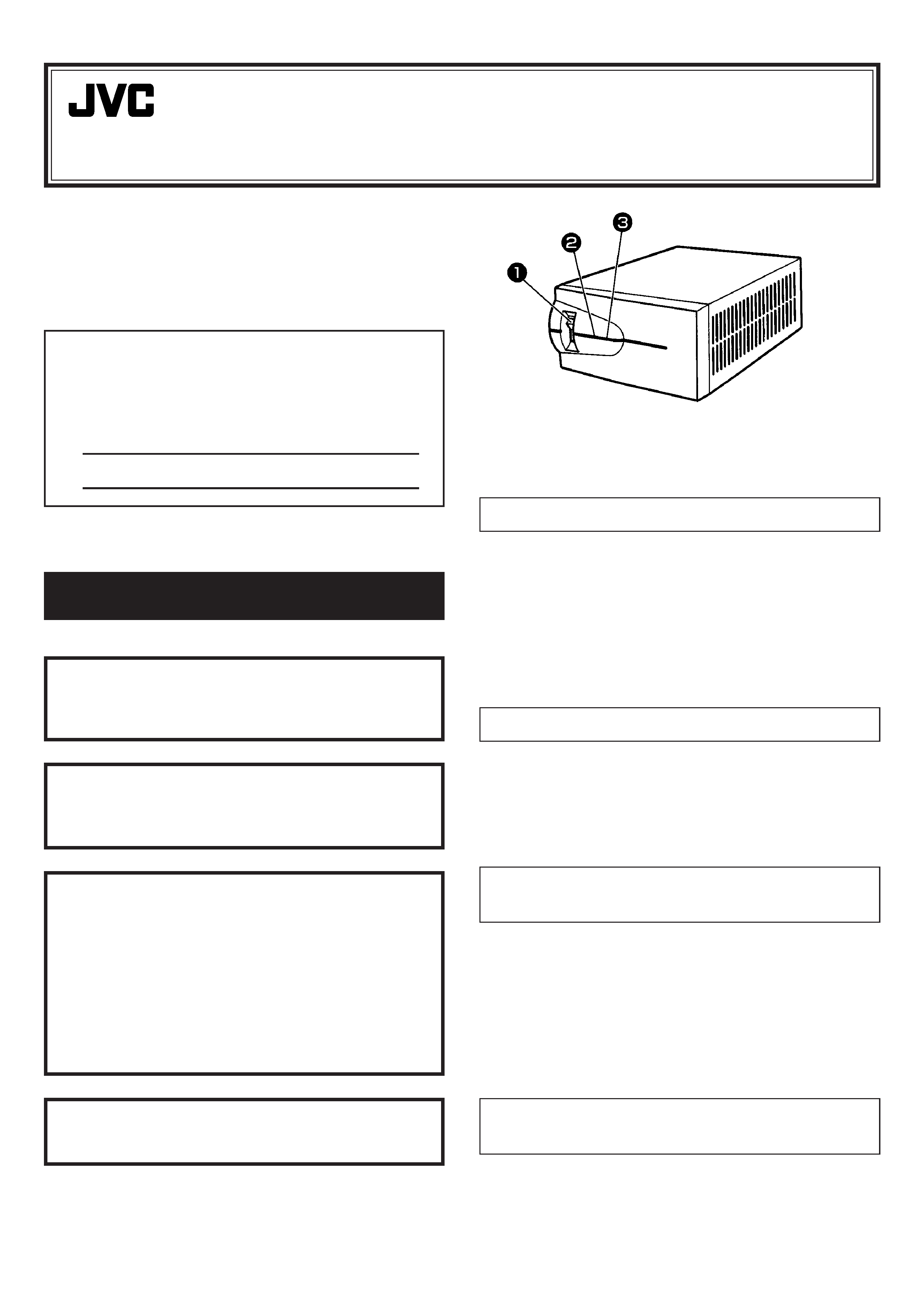
Safety precautions
1 Breaker/power switch
2 Power lamp (Green LED)
3 Ground indicator lamp (Red LED)
INTRODUCTION
JVC Isolation Transformer AA-V31E is designed to protect
electronic microprocessor-based systems from problems
caused by power line disturbances.
The model you have purchased is designed for use
together with the AC Power Adapter AA-V112E and
MICRO HD CAMERA DZ-VCA1SE for medical applica-
tions.
INSPECTION
Remove the Isolation Transformer from the shipping
container and inspect it for shipping damage. Do not
install or operate the product if it appears to be damaged
in any way. If damaged, notify the carrier and seller
immediately.
ENVIRONMENTAL
CONSIDERATIONS
This Isolation Transformer has environmental require-
ments similar to other medical devices. It has been
designed for indoor use only, in areas where it will not be
exposed to excessive dust or moisture. Make certain that
there is adequate air flow around the unit. Do not place
objects on top of or near the unit which could obstruct the
air vents. For installation, please refer to the MICRO HD
CAMERA DZ-VCA1SE Instruction Book.
SIZING INFORMATION AND
INSTALLATION PROCEDURE
The name plate on the rear panel lists the Isolation
Transformer voltage and current ratings. Observe that the
input current rating is not exceeded when connecting
equipment. Ask that installation be performed by a JVC
authorized dealer.
For Customer Use:
Enter below the Model No. and Serial No. which
are located on the rear of the cabinet. Retain this
information for future reference.
Model No.
Serial No.
LYT0469-001B
SPECIFICATIONS
Isolation Transformer
sManufacturer
: Victor Company of Japan Limited
sModel No.
: AA-V31E
sClassification
: CLASS I
sInput
: 230 V AC
1.50 A 50 Hz
sOutput
: 120 V AC
2.7 A 50 Hz
Accessories
sPlug retainer bracket
x 4
sTorx head screw
x 11
sCover plate
x 3
sFlat washer
x 4
sSplit locking washer
x 11
sInput cord holder
x 1
TECHNICAL AND SERVICE
ASSISTANCE
JVC offers technical and customer service assistance.
Please contact us at the following address.
JVC PROFESSIONAL PRODUCTS (UK) LIMITED
ULLswater House, Kendel Avenue, London W3 OXA,
United Kingdom
TEL: (0181) 896-6000
FAX: (0181) 896-6060
JVC PROFESSIONAL PRODUCTS GmbH
Grüner Weg 10, 61169 Fiedberg/Hessen, Germany
TEL: (06031) 6050
FAX: (06031) 605180
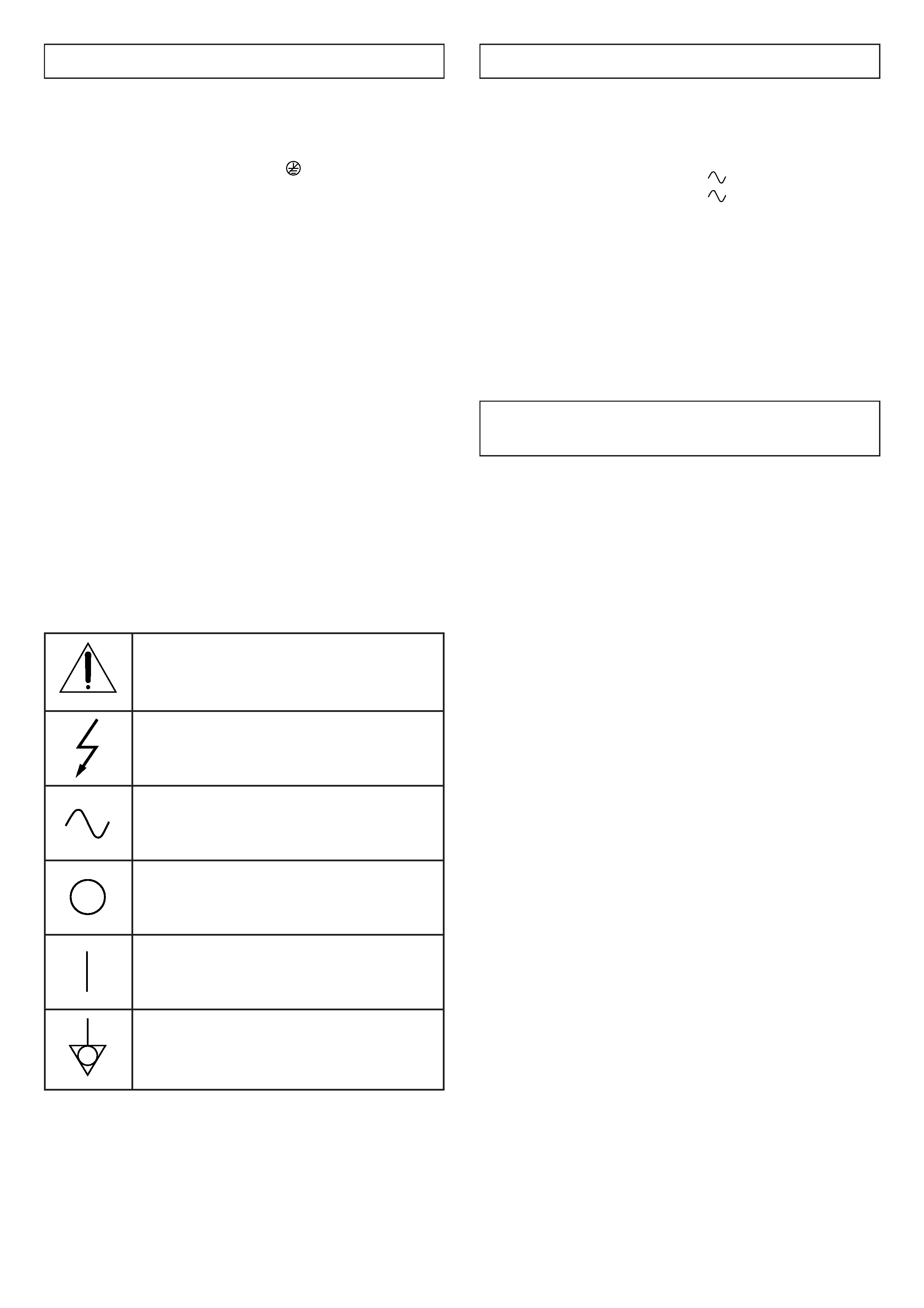
Symbols indicated on this equipment have the follow-
ing meanings.
Attention, consult ACCOMPANYING
DOCUMENTS
Dangerous voltage
Alternating current
Off (power: disconnection from the mains)
On (power: connection to the mains)
Equipotential terminal
OPERATING INSTRUCTIONS
Turn all load equipment ON.
Turn the Isolation Transformer circuit breaker ON.
Observe that the front-panel green LED is illuminated.
Observe that the red LED (marked
) is not illuminated
(place the Isolation Transformer on a non-grounded
surface such as a carpet, wooden table, or magazine for
this test).
CAUTION:
If the red LED is continuously flashing, the wall receptacle
(powering the Isolation Transformer) is not connected to
the system safety ground. Immediately contact an electri-
cian to correct the wiring discrepancy.
IMPORTANT NOTE:
The red LED is not intended to test general wiring integ-
rity. Hot-neutral reversal, neutral-ground reversal, and/or
other wiring errors will not illuminate the red LED.
Once the Isolation Transformer has been properly in-
stalled per the installation instructions, the Isolation
Transformer and load equipment can be turned ON/OFF
via the Isolation Transformer circuit breaker (and if not
externally circuit breaker equipped, via the panel circuit
breaker).
0200IYV*ID*VP