
June 2000
No. 0301
SERVICE MANUAL
MANUEL D 'ENTRETIEN
WARTUNGSHANDBUCH
CAUTION:
Before servicing this chassis, it is important that the service technician read
the "Safety Precautions" and "Product Safety Notices" in this service manual.
ATTENTION:
Avant d'effectuer l'entretien du châassis, le technicien doit lire les
«Précautions de sécurité» et les «Notices de sécurité du produit» présentés
dans le présent manuel.
VORSICHT:
Vor Öffnen des Gehäuses hat der Service-Ingenieur die,,Sicherheitshinweise"
und ,,Hinweise zur Produktsicherheit
" in diesem Wartungshandbuch zu lesen
.
Data contained within this Service
manual is subject to alteration for
improvement.
Les données fournies dans le
présent
manuel
d'entretien
peuvent
faire
l'objet
de
modifications
en
vue
de
perfectionner le produit.
Die in diesem Wartungshandbuch
enthaltenen
Spezifikationen
können
sich
zwecks
Verbesserungenändern.
VTMX900ECT
VTMX900EUK
VTMX905EUK
VTMX905EVPS
VTMX910EUK
VTMX902EL
VTMX930EVPS
VTMX932EL
VTFX2000ELN
VTFX940EVPS
VTFX940EUKN
VTFX940ENA
VTFX942ELN
VTFX940ELN
VTFX952ELN
1-6
Safety instructions
Safety regulations demand that the set be restored to its
original condition and that components identical with the
original types be used.
Safety components are marked by the symbol
All ICs and many other semi-conductors are susceptible to
electrostatic discharges (ESD). Careless handling during repair
may reduce life drastically. When repairing, make sure that you
are conneted with the same potential as the mass of the set via
a wrist wrap with resistance. Keep components and tools on
the same potential.
A set to be repaired should always be connected to the mains
via a suitable isolating transformer.
Never replace any modules or any other parts while the set is
switched on.
Use plastic instead of metal alignment tools. This in order to
prelude short-circuit or to prevent a specific circuit from being
rendered unstable.
Remarks
The direct voltages and oscillograms ought to be measured
relative to the set mass.
EXCEPTION
At the power supply, the DC voltages and the oscillograms at
the primary side are measured to LIVE GND.
The direct voltages and oscillograms mentioned in the
diagrams ought to be measured with a colour bar signal and
the picture carrier at 503.25 MHz (C25).
The oscillograms and direct voltages have been measured in
RECORD or PLAY mode.
The semiconductors, which are mentioned in the circuit
diagram and in the parts lists, are fully exchangeable per
position with the semiconductors in the set, irrespective of the
type designation of these semiconductors.
Sicherheitshinweise
Die Sicherheitsvorschriften erfordern es, daß sich das Gerät
nach der Reparatur in seinem originalen Zustand befindet und
daß die zur Reparatur benutzten Ersatzteile mit den
Originalersatzteilen identisch sind.
Sicherheits-Bauteile sind mit der Markierung
versehen
Alle IC's und Halbleiter sind empfindlich gegen elektrostatische
Entladungen (ESD). Unvorschriftmässige Behandlung von
Halbleitern im Reparaturfall kann zur Zerstörung dieser
Bauteile oder zu einer drastischen Reduzierung der
Lebensdauer führen. Sorgen Sie dafür, daß Sie sich im
Reparaturfall über ein Armband mit Widerstand auf dem
gleichen Potential, wie die Masse des Gerätes befinden. Alle
Bauteile, Werkzeuge und Hilfsmittel sind auf das gleiche
Potential zu legen.
Ein zu reparierendes Gerät ist immer über einen
Trenntransformator an die Netzspannung anzuschließen.
Bei eingeschaltetem Gerät dürfen keine Module oder sonstige
Einzelteile ausgetauscht werden.
Zum Abgleich sind ausschließlich Kunststoffwerkzeuge zu
benutzen (keine Metallwerkzeuge verwenden). Dadurch wird
vermieden, daß ein Kurzschluß entstehen kann oder eine
Schaltung instabil wird.
Anmerkungen
Die Gleichspannung und Oszillogramme sind gegen
Gerätemasse zu messen.
AUSNAHME
Beim Netzteil sind die Gleichspannungen und Oszillogramme
auf der Primärseite gegen Live GND gemessen.
Die Gleichspannungen und Oszillogramme angeführt in den
Schaltbildern sollen unter folgenden Bedingungen gemessen
werden: Farbbalkensignal, Bildträger auf 503.25 MHz (C25)
Die Oszillogramme und Gleichspannungen sind in RECORD
oder PLAY gemessen. Die in den Stücklisten aufgeführten
Bauteile sind positionsweise voll auswechselbar gegen die
Bauteile in dem Gerät, ungeachtet der etwaigen
Typenbezeichungen.
Avertissements
Les normes de sécurité exigent qu'aprés réparation I'appareil
soit remis dans son état d'origine et que soient utilisées les
piéces de rechange identiques à celles spécifiées.
Les composants de sécurité sont marqués
Tout les IC et beaucoup d'autres semi-conducteurs sont
sensibles aux décharger statiques (ESD). Leur longévité
pourrait étre considérablement écourté par le fait qu'aucune
précaution n'est prise à leur manipulation. Lors de réparations
s'assurer de bien étre relié au méme potential que la masse de
l'appareil et enfiler le bracelet serti d'une résistance de
sécurité. Veiller à ce que les composants ainsi que les outils
que I'on utilise soient également à ce potentiel.
Toujours alimenter un appareil à réparer à travers un transfo
d'isolement.
Ne jamais remplacer les modules ni d'autres composants
quand I'appareil est sous tension.
Pour l'ajustage, utiliser des outils en plastique au lieu
d'instruments métalliques. Ceci afin d'éviter les court-circuits et
exclure I'instabilité dans certains circuits.
Observations
La mésure des tensions continues et des oscillogrammes doit
se faire par rapport à la terre de l'appareil.
EXCEPTION
Sur l'unité d'alimentation la tension continue et l'oscillogramme
sont mesurés sur le côte primaire en Live GND.
La mésure des tensions continues et des oscillogrammes
figurant sur le schéma doit se faire dans un signal de barre
couleur porteuse image sur 503.25 MHz (C25).
Les oscillogrammes et tension sont mésurées en mode
RECORD ou PLAY.
Les semi-conducteurs indiqués dans le schéma de principe et
à la liste des compostants, sont interchangeables par repère
sur ce chassis avec les semi-conducteurs de l'appareil quelle
que soit la désignation de type donnée sur ces semi-
conducteurs.
Veiligheidsinstructies
Veiligheidsbepalingen vereisen, dat het apparaat in zijn
oorspronkelijke toestand wordt teruggebracht en dat
onderdelen, indentiek aan de oorspronkelijke, worden
toegepast.
De veiligheidsonderdelen zijn aangeduid met het symbool
Alle IC's en vele andere halfgeleiders zijn gevoelig voor
elektrostatische ontladingen (ESD). Onzorgvuldig behandelen
tijdens reparatie kan de levensduur drastisch doen
verminderen. Zorg ervoor, dat U tijdens reparatie via een
polsband met weerstand verbonden bent met hetzelfde
potentiaal als de massa van het apparaat. Houd componenten
en hulpmiddelen ook op ditzelfde potentiaal.
Sluit een apparaat dat gerepareerd wordt altijd via een
scheidingstransformator aan op de netspanning.
Verwissel nooit modules of andere onderdelen terwijl het
apparaat is ingeschakeld.
Gebruik voor het afregelen plastic i.p.v metalen gereedschap.
Dit om mogelijke kortsluiting te voorkomen of een bepaalde
schakeling instabiel te maken.
Opmerkingen
De gelijksspanningen en oscillogrammen dienen gemeten te
worden ten opzichte van de apparaat aarde.
De gelijksspanningen en oscillogrammen vermeld in de
schema's dienen gemeten te worden met een
kleurbalkensignaal beelddraaggolf op 503.25 MHz (C25).
De oscillogrammen en gelijksspanningen zijn in RECORD of
PLAY mode gemeten.
De halfgeleiders, die in het pricipeschema en in de stuklijsten,
zijn vermeld, zijn per positie volledig uitwisselbaar met de
halfgeleiders in het apparaat, ongeacht de typeaanduiding op
deze halfgeleiders.
GB
D
F
NL
!
!
!
!
1-7
Avvertimenti
Le prescrizioni di sicurezza richiedono che l'apparecchio sia
ricondotto alle condizioni originali e che siano usati ricambi
originali.
Componenti di sicurezza sono marcati con
!
Tutti gli IC e semiconduttori sono sensibili a scariche
elettrostatiche (ESD). Noncuranze durante la riparazione di
semiconduttori possono danneggiarli o condurre ad una
riduzione drastica della durata. Durante la riparazione
assicurarsi di essere collegati allo stesso potenziale attraverso
un bracciale di protezione contro scariche elettrostatiche.
Inoltre tenere anche tutti i componenti e gli attrezzi a questo
potenziale.
Apparecchi da riparare bisogna collegarli sempre via un
trasformatore isolante (separatore) alla tensione normale.
Non scambiare moduli o altri componenti quando l'apparecchio
è in funzione.
Per l'accordo usare soltanto attrezzi di plastica (non usare
attrezzi metallici). Cosí si evitano cortocircuiti e collegamenti
instabili.
Osservazioni
Misurare le tensioni continue e gli oscillogrammi riferiendosi
alla massa dell'apparecchio.
ECCEZIONE
Le tensioni continue e gli oscillogrammi dall'alimentatore sono
misurati sulla parte primaria contro GND-Live.
Le tensioni continue e gli oscillogrammi indicati negli schemi di
collegamento devono essere misurati secondo le condizioni
seguenti: segnale barre colore, portante dell'immagine su:
503.25 MHz (C25).
Gli oscillogrammi e le tensioni continue sono misurati in
RECORD o PLAYBACK.
I componenti indicati nelle liste sono intercambiabili con quelli
nell'apparecchio nonostante l'eventuale denominazione di
modelli.
Avisos
Las instrucciones de seguridad exigen que después de la
reparación el aparato se encuentre en el estado original y que
las piezas de repuesto, utilizadas para la reparación, sean
idénticas a las originales.
Los componentes de seguridad estan marcados con
Todos los IC y semiconductores son sensibles a descargas
electrostáticas (ESD). Un tratamiento no conforme a las
instrucciones de semiconductores en caso de reparación,
podría llevar a la destrucción de estos componentes, o a una
reducción drástica de la duración. Tenga cuidado de que, en
caso de reparación, estar al mismo potencial que la masa del
aparato, por una pulsera con resistencia. Ponga todos los
componentes, herramientas y recursos al mismo potencial.
Para reparar un aparato hay que conectarlo siempre a la
alimentación a traves de un transformador de aislamiento.
Cuando un aparato está en marcha no pueden ser cambiados
módulos u otras piezas de repuesto.
Para los ajustes hay que utilizar exclusivamente herramientas
de plástico (nunca herramientas metálicas). Así se evitaran
cortocircuitos y circuitos inestables.
Notas
Hay que medir las tensiones continuas y los oscilogramas
contra la masa del aparato.
UITZONDERING:
Bij het netgedeelte zijn de gelijkspanningen en oscillogrammen
aan de primaire kant tegen Live GND gemeten.
Las tensiones continuas y los oscilogramas mencionados en
los esquemas tienen que ser medidos de manera siguiente:
señal barra de color portadora de imagen en 503.25MHz (C25)
Los oscilogramas y las tensiones continuas son medidas en
,,RECORD" y ,,PLAYBACK"
Los componentes mencionados en las listas se los puede
cambiar por los componentes en el aparato, a pesar de
eventuales designaciones de tipos.
I
E
!
1-8
Modifications
Description of the system used for publishing
modification data and supplements to the
service manual.
All modification data and supplements to the Service Manual are
published by means of Service Information bulletins.
Each Service information has a number, for example :
A Service Information bulletin concists of a front sheet, as the case
may be followed by supplementary and/or replacement sheets.
Replacement sheets serve to replace existing sheets in the Service
Manual. These sheets are identified by an additional letter after the
page number, for example 5-1a. Page 5-1a then takes the place of
page 5-1.
Supplementary sheets are inserted between the existing sheets in
the Service Manual. These sheets can be identified by an additional
figure following the page number, for example 5-1-1.
Sheet 5-1-1 should be inserted after page 5-1.
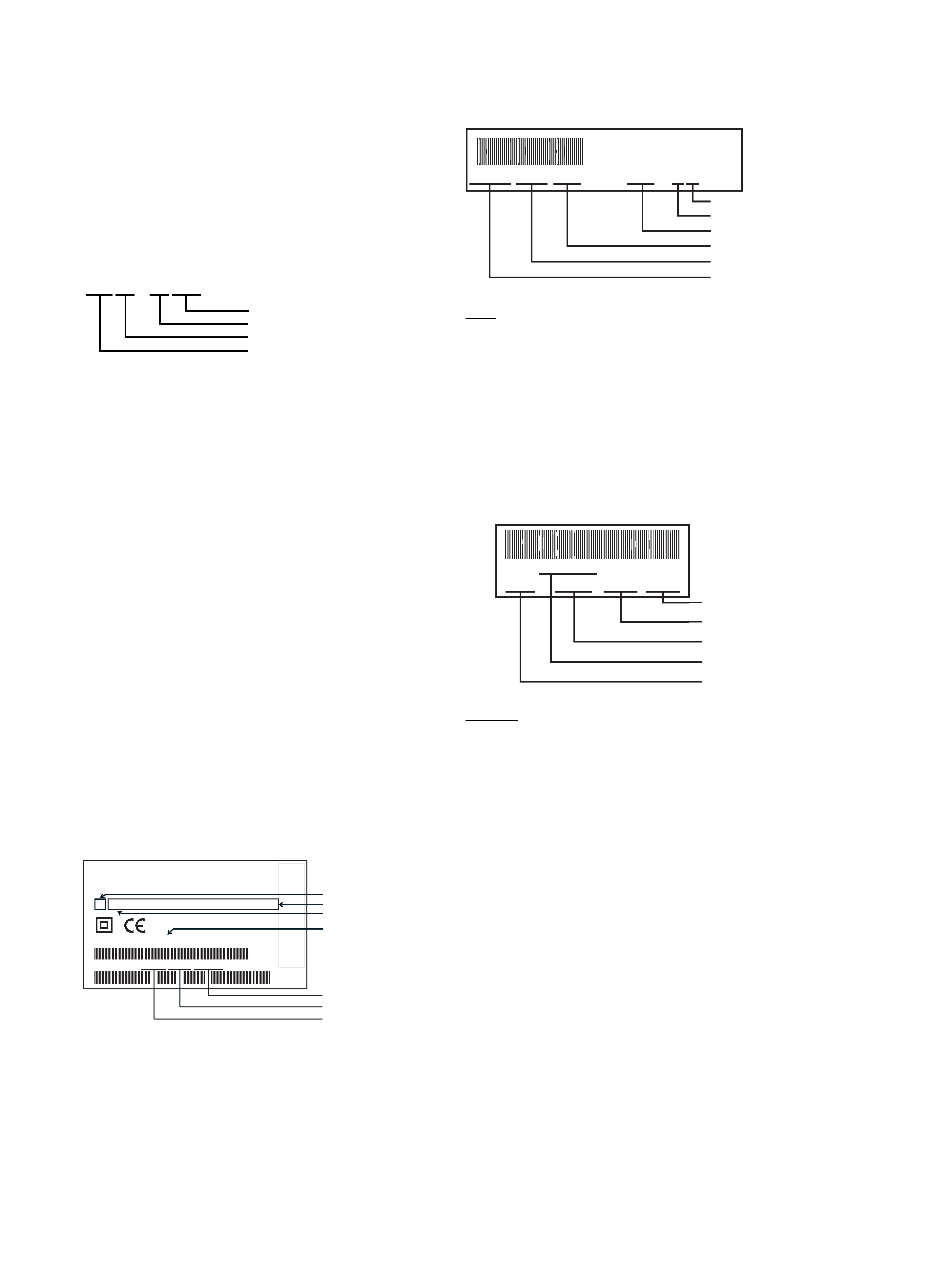
Description of the system by means of which
modifications are indicated in the recorder.
All important parts of the recorder, such as tape deck, p.c. boards
and modules, are provided with a sticker. These stickers specify a
number of product data. The meaning of this data will now be
explained for the most important sections.
The complete recorder
The type plate is located at the back of the recorder, below an
example of such a type plate is given.
Type plate :
Note :
- In the case of an important modification to the recorder the
production code on the type plate is increased by one.
E.g. 37 becomes 38.
- In the case of an important modification to the service
documentation the evolution code on the type plate is increased
by one.
E.g. AA becomes AB.
220-240 V ~
220-240 V ~
S AA
50Hz
50Hz
MADE IN EUROPE
MADE IN EUROPE
MODEL NO:
MODEL NO:
AAA BBB CCC DDD EEE FFF GGG
PROD.NO:
PROD.NO:
VR110/02
VN 37 0015 123456
VN 37
123456
S
H
O
W
V
IE
W
IS
AT
R
A
D
E
M
A
R
K
A
P
P
L
IE
D
SHOWVIEW
IS
A
TRADEMARK
APPLIED
G
E
M
S
T
A
R
D
E
V
E
L
O
P
M
E
N
T
C
O
R
P
.
GEMST
AR
DEVELOPMENT
CORP
.
F
O
R
B
Y
G
E
M
S
T
A
R
D
E
V
E
L
O
P
M
E
N
T
C
O
R
P
.
FOR
BY
GEMST
AR
DEVELOPMENT
CORP
.
S
H
O
W
V
IE
W
S
Y
S
T
E
M
IS
M
A
N
U
F
A
C
T
U
R
E
D
SHOWVIEW
SYSTEM
IS
MANUF
ACTURED
U
N
D
E
R
L
IC
E
N
S
E
F
R
O
M
UNDER
LICENSE
FROM
Tape deck
Note :
The production code and the serial number on the tape deck need
not correspond to the production code and the serial number on the
type plate.
Printed panels
The stickers are generally located on the track side of the module.
Example :
Remarks :
The production code number will not always be mentioned.
In case of an important modification, the last figure of the factory code
number (point number) is increased by one. E.g. 6635.1 becomes
6635.2.
GB
12345678 009271 AT-P2/0
00151 10WD51
Production code
Factory indication
Production date
Tape deck type
Factory code number
Serial number
AVR 01102
12345
KW 015
WD 01 123456
Serial number
Production code
Production week
Printed board name
Factory code
VR 00 - 01 GB
Language
Sequence number
Year
Video cassette recorder
Service
Serial number
Production date
Production center (VN),
Production code
Type number
Option codes (A-G)
Evolution code

1-9
GB
D
TECHNICAL DATA
TECHNISCHE DATEN
CARACTERISTIQUES
Mains voltage .................................. Netzspannung ...................................... Tension secteur ............................. 220 - 240 V, +/- 10%
Mains frequency ............................. Netzfrequenz ....................................... Fréquence ...................................... 45 - 65 Hz
Power consumption: ...................... Leistungsaufnahme: .............................. Puissance absorbée: ..................... mono 12.5 W during operation
HiFi
16 W during operation
without Low Power Standby ...... Standby ................................................ mode veille normal ........................ mono 4 W
during standby
HiFi 4.4 W during standby
with Low Power Standby ........... Standby mit geringem Verbrauch ........ mode veille faible consommation .. <
4 W standby
Ambient temperature ...................... Raumtemperatur .................................. Température ambiante .................. +10°C to +35°C
Relative humidity ............................ Relative Luftfeuchtigkeit ...................... Humidité relative ............................ 20 - 80 %
Dimensions ..................................... Abmessungen ...................................... Encombrement .............................. 380 x 260 x 94 mm
Weight ............................................. Gewicht ................................................ Poids .............................................. 3,7 kg
Fast forward/rewind time (turbo) ... Vor-/Rückspulzeit (turbo) ..................... Temps (re-)bobinage (turbo) ......... typ. 100s (E180 cass.)
Position of use ................................ Betriebslage ......................................... Position d'emploi ........................... horizontally, max. 15°
Video resolution .............................. Video-Auflösung .................................. Puissance absorbée ......................
240 lines
Audio ............................................... Audio .................................................... Audio SP: Linear Audio ................. 80Hz - 10kHz (
+/-6 dB)
Audio LP: Linear Audio .................. 80Hz - 5kHz (
+/-6 dB)
Stereo FM Audio ............................ 20Hz - 20kHz (
+/-3dB)
TECHNISCHE GEGEVENS
DATOS TECNICOS
DATI TECNICI
Netspanning .................................... Tensión de red ..................................... Tensione di alimentazione ............. 220 - 240 V
Netfrequentie .................................. Frecuencia de red ................................ Frequenza di rete .......................... 45 - 65 Hz
Opgenomen vermogen: .................. Consumo de potencia: ......................... Potenza assorbita: ......................... mono 12.5 W during operation
HiFi
16 W during operation
zonder Low Power Standby ...... sin standby de bajo consumo .............. in attesa non a basso consumo .... mono 4 W during standby
HiFi 4.4 W during standby
met Low Power Standby ........... con standby de bajo consumo ............. in attesa a basso consumo ............ <
4 W standby
Omgevingstemperatuur .................. Temperatura ambiente ........................ Temperatura ambiente .................. +10°C to +35°C
Relatieve vochtigheid ..................... Humedad relativa ................................ Umiditá relativa .............................. 20 - 80 %
Afmetingen ...................................... Dimensiones ........................................ Dimensioni ..................................... 380 x 260 x 94 mm
Gewicht ........................................... Peso ..................................................... Peso ............................................... 3,7 kg
Vooruit/terugspoeltijd (turbo) .......... tiempo de (re-)bobinado (turbo) .......... Tempo di (ri-)avvolgimento (turbo) typ. 100s (E180 cass.)
Gebruikspositie ............................... Posición de uso ................................... Posizione di funzionamento .......... horizontally, max. 15°
Opplossend vermogen ................... Resolución video ................................. Risoluzione video ..........................
240 lines
Audio ............................................... Audio .................................................... Audio SP: Linear Audio ................. 80Hz - 10kHz (
+/-6 dB)
Audio LP: Linear Audio .................. 80Hz - 5kHz (
+/-6 dB)
Stereo FM Audio ............................ 20Hz - 20kHz (
+/-3dB)
F
Euroconnector (AV1) SCART plug 1
Connection to TV, monitor, projection TV ...
Pin 1
ARO (audio right out) 500 mV
rms +/- 3 dB
R
out
1 kOhm
Pin 2
ARI (audio right in)
0,2 V
rms to 2Vrms
R
in
10 kOhm
Pin 3
ALO (audio left out)
500 mV
rms +/- 3 dB
R
out
1 kOhm
Pin 6
ALI (audio left in)
0,2 V
rms to 2 Vrms
R
in
10 kOhm
Pin 7
Blue (out) **)
Pin 8
Switching output:
(with R
load = 10kOhm, C load < 2nF)
low:
2 V
high: 9.5 V
rise time: 5 ms
Pin 11 Green (out) **)
Pin 15 Red (out) **)
Pin 16 Blanking (out) **)
loop through enabled during
standby, view-mode
Pin 19 CVBS II (video out)
1 V
pp +1/-2dB
R
out 75 Ohm
Pin 20 CVBS I (video in)
1 V
pp +3/-3dB
R
in
75 Ohm
**) passive loop through from AV2
Euroconnector (AV2) SCART plug 2
Connection to decoder, SAT tuner, video disc, 2nd VCR ....
Pin 1
ARO (audio right out) 500 mV
rms +/- 3 dB
R
out
1 kOhm
Pin 2
ARI (audio right in)
0,2 V
rms
to 2 V
rms
R
in
10 kOhm
Pin 3
ALO (audio left out)
500 mV
rms +/- 3 dB
R
out
1 kOhm
Pin 6
ALI (audio left in)
0,2 V
rms
to 2 V
rms
R
in
10 kOhm
Pin 7
Blue (in) *)
Pin 8
Switching input only
low: 2 V (low)
R
in
10 kOhm
high: 4.5 V (high)
R
in
10 kOhm
Pin 11 Green (in) *)
Pin 15 Red (in) *)
Pin 16 Blanking (in) *)
loop through enabled during
standby, view-mode
Pin 19 CVBS II (video out)
1 V
pp +1/- 2dB
R
out 75 Ohm
Pin 20 CVBS I (video in)
1 V
pp +3/-3 dB
R
in
75 Ohm
*) passive loop through to Euroconnector AV1
Cinch Audio/Video input on front panel (OPTION)
Audio:
AINFR (audio right in) red 0.2 V
rms to 2 Vrms
typ. 500 mV
rms
AINFL (audio left in) white 0.2 V
rms to 2 Vrms
typ. 500 mV
rms
Input impedance
47 kOhm
Video:
VFR
yellow
1 V
pp + 3 / -3 dB
Input impedance
75 Ohm
Cinch Audio Out Rear (OPTION)
AOUT1R (audio right out) red
500 mV
rms +/- 3 dB Rout1 kOhm
AOUT1L (audio left out) white
500 mV
rms +/- 3 dB Rout1 kOhm
This outputs are in parallel with the corresponding outputs on
Euroconnector 1.
TUMOD
Modulator:
Frequency range loop through
45 MHz - 860 MHz
Gain:
ANT IN - TV OUT
2 dB + 3 / -2 dB
ANT IN - TUN OUT
2 dB + 3 / -2 dB
Switch for RF input attenuation
NO
Frequency range out (tuned by IIC bus) Ch 21 - Ch55
Tuner:
Frequency range
43 MHz - 860 MHz
for UK 450 MHz - 860MHz
Input voltage max.
< 100 dBµV
min.
> 60 dBµV
NL
E
I