SERVICE MANUAL
SPECIFICATIONS AND PARTS ARE SUBJECT TO CHANGE FOR IMPROVEMENT
Digital Media Products Division
VIDEO CASSETTE RECORDER
2001
November
SM8106
This video deck is a VHS type video
recorder. For proper operation, only
the VHS type cassette must be
used.
UT MECHANISM
When Servicing the Mechanism:
This video cassette recorder uses a UT
mechanism.
When servicing the UT mechanism, refer
to the "UT mechanism service manual
(SM 8107)"
Information on UT Mechanism
The UT mechanism is the result of upgrading
the U4 mechanism found in home-use VCRs
and applying it to time-lapse VCRs.
Although some components still have the
stamp "U4", the method of servicing the UT
mechanism differs from that for U4
mechanism, and the UT mechanism also uses
exclusive components. When servicing the UT
mechanism, be sure to refer to the "UT
mechanism service manual".
VTL4024E
Cautions .......................................................
CAUTIONS-1
Notes When Using Service Manual ............. CAUTIONS-2
CHAPTER 1
GENERAL INFORMATION
1. Specifications ........................................................ 1-1
2. Comparison with Previous Model ......................... 1-2
2.1
Comparison of Features ................................ 1-2
2.2
Comparison of ICs ......................................... 1-3
3. Memory Data (Warning Memory Data)
Display Function .................................................... 1-4
3.1
Memory Data on Cylinder Usage Hours
and Number of Recordings on Tape ............. 1-4
3.2
Warning Memory Data .................................... 1-5
4. Resetting Functions and Settings ......................... 1-7
4.1
Counter Reset ................................................ 1-7
4.2
Alarm Reset .................................................... 1-7
4.3
Operation Reset ............................................. 1-7
4.4
Resetting Warning Memory Data ................... 1-7
4.5
Resetting HEAD (Cylinder Usage Hours) ...... 1-8
4.6
Resetting to Factory Defaults ......................... 1-8
5. How to Remove Cassette When
Mechanism Malfunctions ...................................... 1-9
6. Extract from the Instruction Manual ....................... 1-10
Controls and Functions .................................. 1-10
CHAPTER 2
DISASSEMBLY
1. Before Starting Disassembly ................................ 2-1
1.1
Locations of Components .............................. 2-1
1.2
Disassembly Flowchart .................................. 2-1
2. Disassembly Procedure ....................................... 2-2
2.1
Top Cover, Front Panel ................................... 2-2
2.2
UT-FL Mechanism .......................................... 2-2
2.3
UT Mechanism ............................................... 2-3
2.4
Front Frame, FSW Circuit Board,
JSW Circuit Board, LED Circuit Board ........... 2-3
2.5
Rear Panel, RJK Circuit Board,
MAS Circuit Board ........................................... 2-4
3. Cautions When Reinstalling UT Mechanism ....... 2-5
CHAPTER 3
SERVICE POSITION/
ELECTRIC CIRCUIT
ADJUSTMENT
SERVICE POSITION
1. Checking for Normal Operation ............................ 3-1
2. Checking Circuits (Boards) ................................... 3-2
CONTENTS-1
ELECTRIC CIRCUIT ADJUSTMENT
1. Test Equipment and Jigs Necessary
for Adjustment .......................................................3-3
2. Connections for Test Equipment .......................... 3-3
3. Cautions during Adjustment ................................. 3-3
4. Servo Circuit Adjustments ..................................... 3-4
4.1
X-Value Adjustment ........................................ 3-4
4.2
Switching Point Adjustment ............................ 3-4
5. Video Circuit Adjustments ..................................... 3-5
5.1
PAL Jog Adjustment ....................................... 3-5
6. Audio Circuit Adjustments ..................................... 3-6
6.1
Playback Level Check ..................................... 3-6
CHAPTER 4
EXPLODED VIEW
1. Cabinet .................................................................. 4-1
2. UT Mechanism [Top view] ..................................... 4-2
3. UT Mechanism [Bottom view] ................................ 4-3
4. UT-FL Mechanism ................................................. 4-4
CHAPTER 5
REPLACEMENT
PARTS LIST
1. Mechanical Parts List ............................................ 5-1
2. Electrical Parts List ................................................ 5-2
CHAPTER 6
SCHEMATIC, CIRCUIT
BOARD AND BLOCK
DIAGRAMS/MICRO-
PROCESSOR PIN
FUNCTION TABLES
MICROPROCESSORPIN FUNCTION TABLE
LCD Driver Microprocessor (IC0701) ......................... 6-1
Main Microprocessor (IC0901) ................................... 6-2
SCHEMATIC DIAGRAMS
Connection Diagram ................................................... 6-5
Front Switch-1 [FSW] ................................................... 6-8
Front Switch-2 [JSW] ................................................... 6-8
LED [LED] .................................................................... 6-9
Rear Jack [RJK] ........................................................... 6-9
[MAS] (For Display)
Main-1
.......................................... 6-6
Contents
Main-2 [MAS] (For Display) .......................................... 6-7
IC Block Diagrams ...................................................... 6-10

CONTENTS-2
BLOCK DIAGRAMS
System Control ............................................................ 6-14
Servo ............................................................................ 6-15
Video ............................................................................ 6-16
Audio ............................................................................ 6-17
LCD Grid Table ........................................................... 6-18
CIRCUIT BOARD DIAGRAMS
FSW ............................................................................. 6-13
JSW ............................................................................. 6-13
LED .............................................................................. 6-13
RJK .............................................................................. 6-13
MAS -Side A- ................................................................ 6-11
MAS -Side B- ................................................................ 6-12
CAUTIONS- 1
Many electrical and mechanical parts have special safety-related characteristics. These are often not evident from visual
inspection nor can the protection afforded by them necessarily be obtained by using replacement components rated for a
higher voltage, wattage, etc. Replacement parts which have these special safety characteristics are identified in this
Service Manual. Electrical components having such features are identified by marking with a
on the schematics and
the parts list in this Service Manual. The use of a substitute replacement component which does not have the same
safety characteristics as the HITACHI recommended replacement one, shown in the parts list in this Service Manual, may
create shock, fire, or other hazards. Product safety is continuously under review and new instructions are issued from
time to time. For the latest information, always consult the current HITACHI Service Manual. A subscription to, or
additional copies of HITACHI Service Manual may be obtained at a nominal charge from HITACHI SALES CORPORATION.
PRODUCT SAFETY NOTICE
Cautions
Lithium battery; danger of explosion if battery is incorrectly replaced. Replace only with the same or equivalent type
recommended by the equipment manufacturer. Discard used batteries according to manufacuturer's instructions.
When replacing the lithium battery it is important to use the same type and connect it correctly.
WARNING:
Lithium batteries contain dangerous chemicals.
Handle and dispose of with great care.
Do not throw in a fire.
Do not short circuit it.
For disposal place in a plastic bag and put in waste bin.
CAUTION
CAUTIONS- 2
Notes When Using Service Manual
The following shows the contents to be noted when using service manual:
1. Value units used in parts list
This table shows locations of each part on circuit board
diagrams. The locations are indicated using the guide
scales on the external lines of diagrams.
1) One diagram indicated for each board
The values, dielectric strength (power capacitance) and
tolerances of the resistors (excluding variable resistors)
and capacitors are indicated in the schematic diagrams
using abbreviations.
[Resistors]
Certain symbols are indicated below for value units of
resistors, capacitors and coils in parts list. When you
read them note the following regular indications:
Indication in list
Regular indication
KOHM ........................................... k
UF ................................................ µF
PF ................................................ pF
UH ................................................ µH
MH .............................................. mH
Parts
Resistor
Capacitor
Coil
2) Two diagrams indicated for each board
2. Values in schematic diagrams
Item
Value
Tolerance
Power
capacitance
Indication
No
indication ...........
K ....................... k
M ....................... M
No
indication ........
±5%
(All
tolerances
other
than
±5%
are ..... indicated
in
schematic
diagrams)
No
indication .......
1/8W
(1/16W
for
leadless
resistors
without
indication)
All
capacitances
other
than
the
above
are
indicated
in
schematic
diagrams.
[Capacitors]
Item
Value
Dielectric
strength
Indication
No
indication .......... µF
P ....................... pF
No
indication ........
50V
(All
dielectric
strengths
other
than
50Vare
indicated
in
schematic ... diagrams)
Item
Value
Indication
µ ....................... µH
m ....................... mH
[Coils]
3. Identifications of sides A/B in
circuit board diagrams
1) Board having a pattern on one side and parts on both
sides.
Side A:
Shows discrete parts, viewed from the
pattern
side.
Side B: Shows leadless parts, viewed from the
pattern side.
2) Board having patterns on both sides and parts on
both sides.
Side A:
Shows parts and patterns which can be
seen
when the case is opened.
Side B: Shows parts and the pattern on the back of
side A.
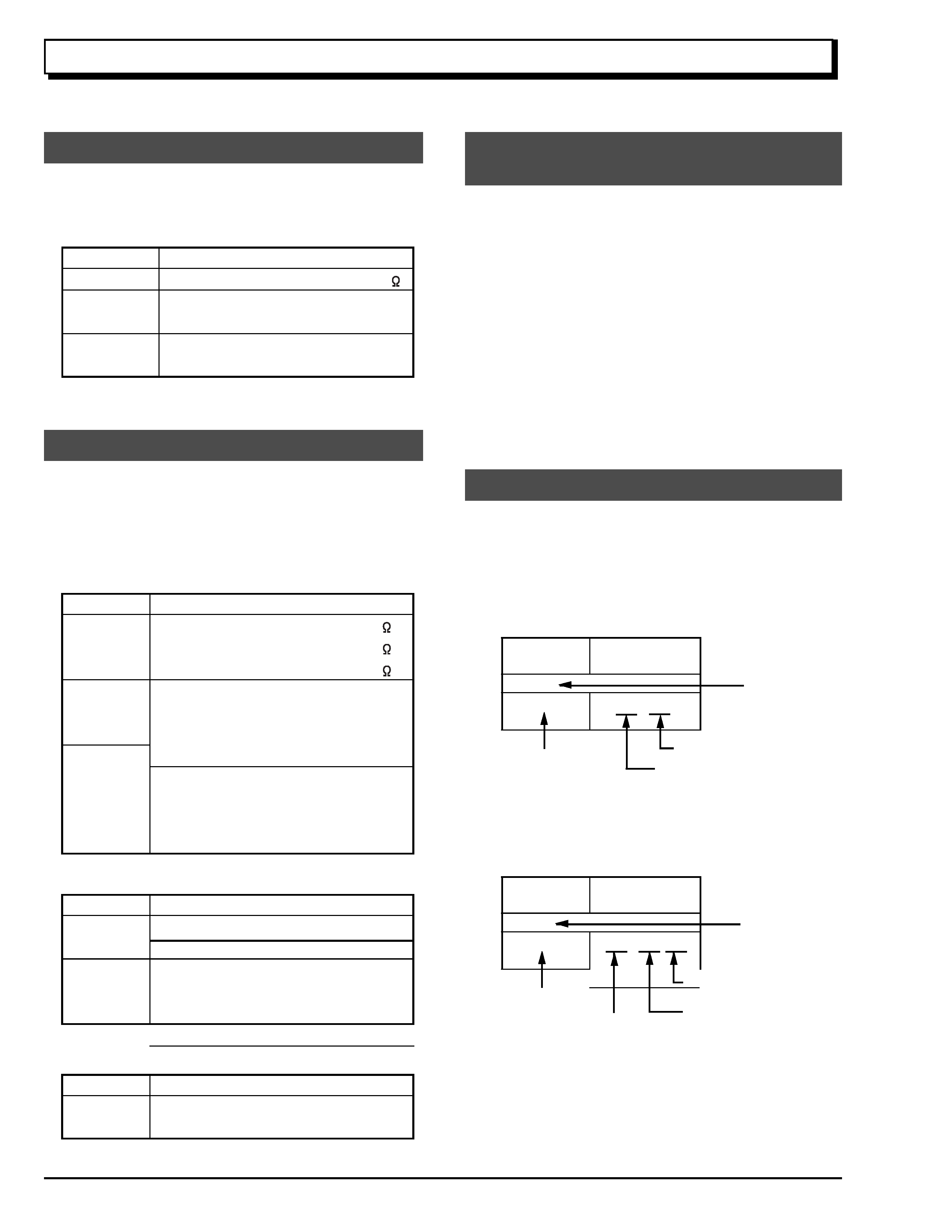
4. Table for indexing locations of parts
Parts
Location
2
A
Symbol
No.
IC
IC1201
Type
of
part
Zone "A" on board diagram
Circuit No.
Zone "2" on board diagram
Parts
Location
A
-
2
A
Symbol
No.
IC
IC1201
Zone "2" on board
diagram
A: Shows side A
B: Shows side B
Zone "A" on board
diagram
Type of
part
Circuit No.