SERVICE MANUAL
Digital Media Products Division, Tokai
VIDEO CASSETTE RECORDER
SPECIFICATIONS AND PARTS ARE SUBJECT TO CHANGE FOR IMPROVEMENT
This video deck is VHS type video
recorder. For proper operation, only
the VHS type cassette must be
used.
TK
No. 5101E
S:\DOCS\U23\H79P0UD\HH79P1CV1.EPS
CONTENTS
MAIN SECTION
Specifications .......................................................1- 1 -1
Important Safety Precautions ..............................1- 2 -1
Standard Notes for Servicing ...............................1- 3 -1
Preparation for Servicing .....................................1- 4 -1
Operating Controls and Functions .......................1- 5 -1
Cabinet Disassembly Instructions .......................1- 6 -1
Electrical Adjustment Instructions .......................1- 7 -1
Block Diagrams ....................................................1- 8 -1
Function Indicator Symbol .................................. 1- 8 -11
SchematicDiagrams / CBA' s and Test Points ...1- 9 -1
Waveforms ...........................................................1- 9 -8
Wiring Diagram ................................................1-10-1
System Control Timing Charts ..............................1-11-1
IC Pin Function .....................................................1-12-1
Lead Identifications ...............................................1-13-1
DECK MECHANISM SECTION
Standard Maintenance ......................................... 2- 1 -1
Fixture and Tape for Adjustment ......................... 2- 2 -1
Mechanical Alignment Procedures ...................... 2- 3 -1
Disassembly / Assembly Procedures of
Deck Mechanism ..... 2- 4 -1
Alignment Procedures of Mechanism .................. 2- 4 -9
EXPLODED VIEWS AND PARTS LIST SECTION
Exploded Views ................................................... 3- 1 -1
Mechanical Parts List ........................................... 3- 2 -1
Electrical Parts List .............................................. 3- 3 -1
VT-FX665A
VT-FX665AC
March
2001
VIDEO-IN
AUDIO-IN
L
R
CHANNEL
REC/IRT
REW
F.FWD
PLAY
STOP/EJECT
TRACKING
POWER

TABLE OF CONTENTS
Specifications.................................................................................................................................................... 1- 1 -1
Important Safety Precautions............................................................................................................................ 1- 2 -1
Standard Notes for Servicing ............................................................................................................................ 1- 3 -1
Preparation for Servicing .................................................................................................................................. 1- 4 -1
Operating Controls and Functions .................................................................................................................... 1- 5 -1
Cabinet Disassembly Instructions..................................................................................................................... 1- 6 -1
Electrical Adjustment Instructions ..................................................................................................................... 1- 7 -1
Block Diagrams................................................................................................................................................. 1- 8 -1
Function Indicator Symbols..............................................................................................................................1- 8 -11
Schematic Diagrams / CBA' s and Test Points ................................................................................................. 1- 9 -1
Waveforms ........................................................................................................................................................ 1- 9 -8
Wiring Diagram ................................................................................................................................................. 1-10-1
System Control Timing Charts .......................................................................................................................... 1-11-1
IC Pin Function ................................................................................................................................................ 1-12-1
Lead Identifications ........................................................................................................................................... 1-13-1
MAIN SECTION
VIDEO CASSETTE RECORDER
VT-FX665A
VT-FX665AC
MAIN SECTION
q Specifications
q Preparation for Servicing
q Adjustment Procedures
q Schematic Diagrams
q CBA' s

SPECIFICATIONS
Description
Unit
Minimum
Nominal
Maximum
Condition
1. Video
1-1 Video Output (PB)
Vp-p
0.8
1.0
1.2
1-2 Video Output (R/P)
Vp-p
0.8
1.0
1.2
1-3 Video S/N Y (R/P)
dB
41
44
SP Mode
1-4 Video Color S/N AM (R/P)
dB
35
44
SP Mode
1-5 Video Color S/N PM (R/P)
dB
33
37
SP Mode
1-6 Resolution (PB)
Line
210
230
SP Mode
2. Servo
2-1 Jitter Low (R/P)
µs
0.05
0.1
SP Mode
2-2 Wow & Flutter (R/P)
%
0.2
0.4
SP Mode
3. Normal Audio
3-1 Output (PB)
dBV
-10
-6
-2
3-2 Output (R/P)
dBV
-10
-6
-2
SP Mode
3-3 S/N (R/P)
dB
38
43
SP Mode
3-4 Distortion (R/P)
%
2
4.0
SP Mode
3-5 Freq. response (R/P) at 200Hz
dB
-6
0
SP Mode
(-20dB ref. 1kHz) at 8kHz
dB
-6
-1.5
SP Mode
4. Tuner
4-1 Video Output
Vp-p
0.8
1.0
1.2
E-E Mode
4-2 Video S/N (S/N Y signal)
dB
40
47
E-E Mode
4-3 Audio Output (1kHz)
dBV
-10
-6
-4
E-E Mode
4-4 Audio S/N (1kHz)
dB
40
46
E-E Mode
Note: Nominal specs represent the design specs. All units should be able to approximate these some will exceed
and some may drop slightly below these specs. Limit specs represent the absolute worst condition that still might be
considered acceptable; In no case should a unit fail to meet limit specs.
1-1-1

IMPORTANT SAFETY PRECAUTIONS
Product Safety Notice
Some electrical and mechanical parts have special
safety-related characteristics which are often not evi-
dent from visual inspection, nor can the protection they
give necessarily be obtained by replacing them with
components rated for higher voltage, wattage, etc. Parts
that have special safety characteristics are identified by
a
on schematics and in parts lists. Use of a substi-
tute replacement that does not have the same safety
characteristics as the recommended replacement part
might create shock, fire, and/or other hazards. The
Product's Safety is under review continuously and new
instructions are issued whenever appropriate. Prior to
shipment from the factory, our products are carefully
inspected to confirm with the recognized product safety
and electrical codes of the countries in which they are
to be sold. However, in order to maintain such compli-
ance, it is equally important to implement the following
precautions when a set is being serviced.
Precautions during Servicing
A. Parts identified by the
symbol are critical for
safety. Replace only with part number specified.
B. In addition to safety, other parts and assemblies are
specified for conformance with regulations applying
to spurious radiation. These must also be replaced
only with specified replacements.
Examples: RF converters, RF cables, noise block-
ing capacitors, and noise blocking filters, etc.
C. Use specified internal wiring. Note especially:
1) Wires covered with PVC tubing
2) Double insulated wires
3) High voltage leads
D. Use specified insulating materials for hazardous live
parts. Note especially:
1) Insulation tape
2) PVC tubing
3) Spacers
4) Insulators for transistors
E. When replacing AC primary side components
(transformers, power cord, etc.), wrap ends of wires
securely about the terminals before soldering.
F. Observe that the wires do not contact heat produc-
ing parts (heatsinks, oxide metal film resistors, fus-
ible resistors, etc.).
G. Check that replaced wires do not contact sharp
edges or pointed parts.
H. When a power cord has been replaced, check that
5 - 6 kg of force in any direction will not loosen it.
I. Also check areas surrounding repaired locations.
J. Use care that foreign objects (screws, solder drop-
lets, etc.) do not remain inside the set.
K. Crimp type wire connector
The power transformer uses crimp type connectors
which connect the power cord and the primary side
of the transformer. When replacing the transformer,
follow these steps carefully and precisely to prevent
shock hazards.
Replacement procedure
1) Remove the old connector by cutting the wires at a
point close to the connector.
Important: Do not re-use a connector. (Discard it.)
2) Strip about 15 mm of the insulation from the ends of
the wires. If the wires are stranded, twist the strands
to avoid frayed conductors.
3) Align the lengths of the wires to be connected. Insert
the wires fully into the connector.
4) Use a crimping tool to crimp the metal sleeve at its
center. Be sure to crimp fully to the complete closure
of the tool.
L. When connecting or disconnecting the internal con-
nectors, first, disconnect the AC plug from the AC
outlet.
1-2-1
Safety Check after Servicing
Examine the area surrounding the repaired location for
damage or deterioration. Observe that screws, parts,
and wires have been returned to their original positions.
Afterwards, do the following tests and confirm the speci-
fied values to verify compliance with safety standards.
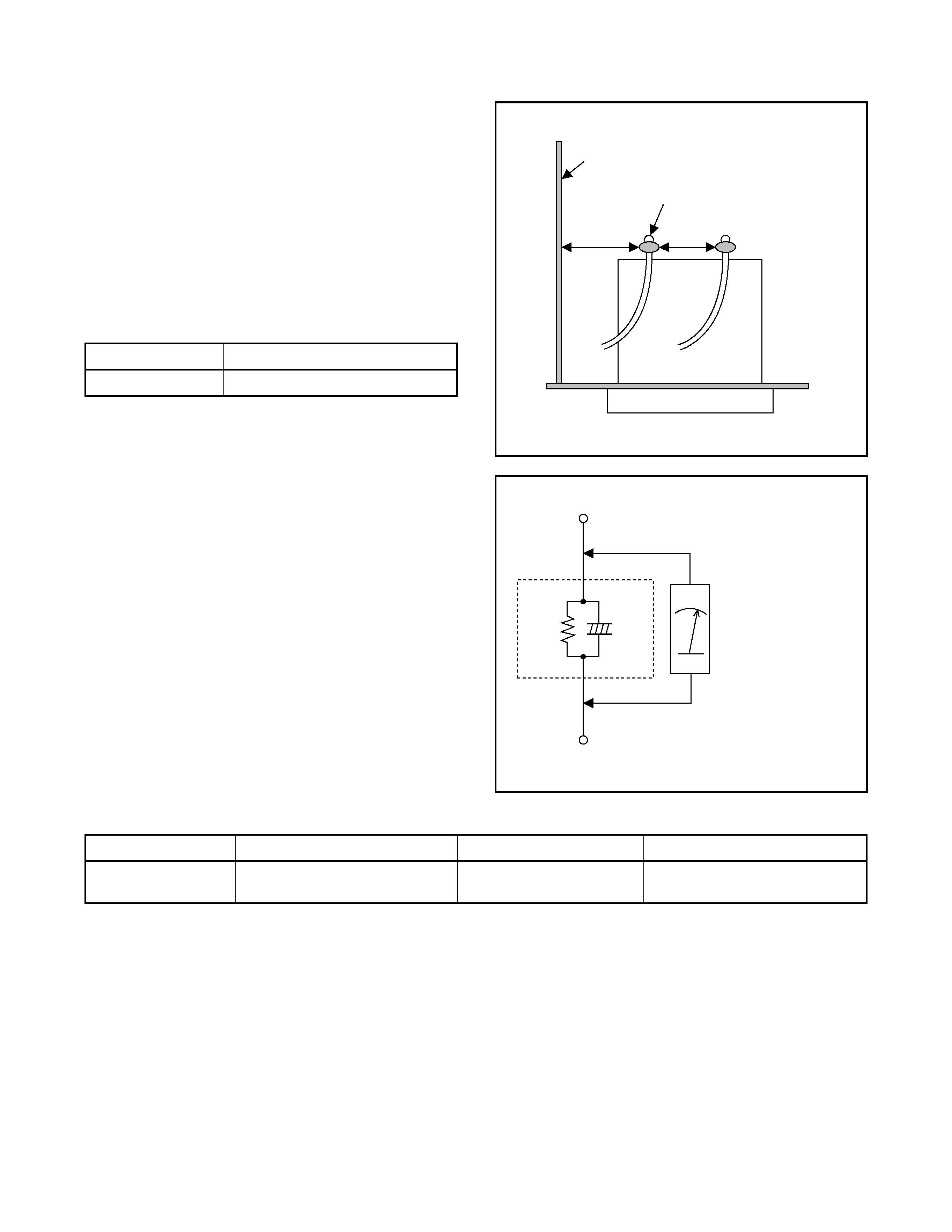
1. Clearance Distance
When replacing primary circuit components, confirm
specified clearance distance (d) and (d') between sol-
dered terminals, and between terminals and surround-
ing metallic parts. (See Fig. 1)
Table 1 : Ratings for selected area
AC Line Voltage
Clearance Distance (d) (d')
120 V
3.2 mm (0.126 inches)
Note: This table is unofficial and for reference only.
Be sure to confirm the precise values.
2. Leakage Current Test
Confirm the specified (or lower) leakage current be-
tween B (earth ground, power cord plug prongs) and
externally exposed accessible parts (RF terminals, an-
tenna terminals, video and audio input and output ter-
minals, microphone jacks, earphone jacks, etc.) is lower
than or equal to the specified value in the table below.
Measuring Method (Power ON) :
Insert load Z between B (earth ground, power cord plug
prongs) and exposed accessible parts. Use an AC
voltmeter to measure across the terminals of load Z.
See Fig. 2 and the following table.
Table 2 : Leakage current ratings for selected areas
AC Line Voltage
Load Z
Leakage Current (i)
Earth Ground (B) to:
120 V
0.15
µF CAP. & 1.5k RES.
Connected in parallel
i
0.5mA Peak
Exposed accessible parts
Note: This table is unofficial and for reference only. Be sure to confirm the precise values.
Chassis or Secondary Conductor
d
d'
Primary Circuit Terminals
Fig. 1
AC Voltmeter
(High Impedance)
Exposed Accessible Part
B
Earth Ground
Power Cord Plug Prongs
Z
1.5k
0.15
µF
Fig. 2
1-2-2