CAUTION:
Before servicing this chassis, it is important that the service technician read the "Safety
Precautions" and "Product Safety Notices" in this service manual.
ATTENTION:
Avant d'effectuer l'entretien du châassis, le technicien doit lire les «Précautions de sécurité»
et les «Notices de sécurité du produit» présentés dans le présent manuel.
VORSICHT:
Vor Öffnen des Gehäuses hat der Service-Ingenieur die ,,Sicherheitshinweise" und ,,Hinweise
zur Produktsicherheit" in diesem Wartungshandbuch zu lesen.
SERVICE MANUAL
MANUEL D'ENTRETIEN
WARTUNGSHANDBUCH
Data
contained
within
this
Service
manual is subject to alteration for
improvement.
Les données fournies dans le présent
manuel d'entretien peuvent faire l'objet
de modifications en vue de perfectionner
le produit.
Die
in
diesem
Wartungshandbuch
enthaltenen Spezifikationen können sich
zwecks Verbesserungen ändern.
APRIL 2001
VIDEO CASSETTE RECORDER
VTMX100ECT
VTMX100EUK
VTMX102EL
VTMX105EVPS
VTMX110EUK
VTMX130EVPS
VTMX132EL
VTFX140ELN
VTFX140ENA
VTFX140EUKN
VTFX140EVPS
VTFX145ENAV
VTFX152ELN
VTFX162ELN
SM0302
SPECIFICATIONS AND PARTS ARE SUBJECT TO CHANGE FOR IMPROVEMENT
This video deck is a VHS type video
recorder
. For proper operation, only
the VHS type cassette must be used.
- +
V T -MX105EVPS, VT -MX130EVPS, VT -FX140ELN,
V T -FX140ENA, VT -FX140EUKN, VT -FX140EVPS
V T -MX100ECT
PA L
VT -MX100EUK, VT -MX102EL,
VT -MX 110EUK, VT -MX132EL
AUDIO
VIDEO
- +
V T -FX145ENA V, VT -FX162ELN
PAL/SECAM
NTSC 4.43
V T -FX152ELN

GB 2
VT-MX100E
Contents
Page
Contents
Page
1
List of PWBs, Features, Technical
specifications
3
Survey of sets and PWB's with software versions 3
Features
4
Technical specification
5
2
Safety instructions, Modifications
6
Safety instructions
6
Modifications
7
3
Direction for use
8
Remote control overview
8
Front overview of the sets
10
Direction for use introduction
12
4
Dismantling instructions
42
Dismantling instructions
42
Dismantling of the motherboard/drive
combination
43
Dismantling the drive
44
5
Service modes, Repair tips
45
Special functions
45
Service test program
45
Repair tips
49
6
Block diagrams, Waveforms, Wiring diagram 53
Block diagram Video
53
Block diagram Audio Mono
54
Block diagram Audio Stereo
55
Supply voltages and Bus diagram
56
Supply voltages and Bus diagram
57
Block diagram Central Control
58
Waveforms
59
7
Circuit diagrams and PWB layouts
60
Power supply (PS)60
Display control (AIO2)61
Central control (AIO1)62
Deck control (DE)63
Variant List Frontend (FV)64
Frontend (FV)65
FM stereo (FM-ST)66
FM Stereo + Nicam (FM-ST-NIC)67
Audio Linear (AL)
68
FM - Audio (AF)69
Video Signal Processing - SECAM (VS-SEC)70
Video Signal Processing (VS)71
VPS/PDC & OSD Part (VPO)72
In/Out Part (IO)73
FOLLOW ME Part (FOME)74
Wiring Diagram
75
Mother board - solder side
76
Mother board - component side
79
Connector print (QBOG1)80
Shuttle board (ASP10)81
Shuttle board (QKP21)81
Test point overview
82
8
Electrical alignments
83
Measuring instruments
83
Setting instructions
83
Video signal processing (VS-SEC)83
Front End (FV)84
Deck electronics (DE)85
Servo System (AIO1)85
Audio Linear (AL)86
Display Control (AIO2)86
9
Circuit descriptions and List of
abbreviations
89
Switched-mode power supply PS (PS Part)
89
Operating unit (DC part)
90
Central Control (AIO part)
91
Deck electronics (DE part)
92
Front end (FV part)
93
Video signal processing VS (VS part)
94
Audio linear (AL part)
96
Audio HiFi - for stereo units (AF part)
97
IN/OUT (IO part)
98
Follow Me (FOME part)
98
VPS/PDC, on-screen display (VPO part)
98
Simple Blockdiagram
99
Simple Blockdiagram FM Audio / Linear Audio
processing
100
List of abbreviations
102
10 Tape deck
105
Drive assembly
105
Adjustments
109
Deck exploded view (TOP)
112
Deck exploded view (BOTTOM)
113
Mechanical parts list
114
11 Exploded views
116
Exploded view set
116
12 Spare parts list
118
List of PWBs, Features, Technical specifications
GB 3
VT-MX100E
1.
1.
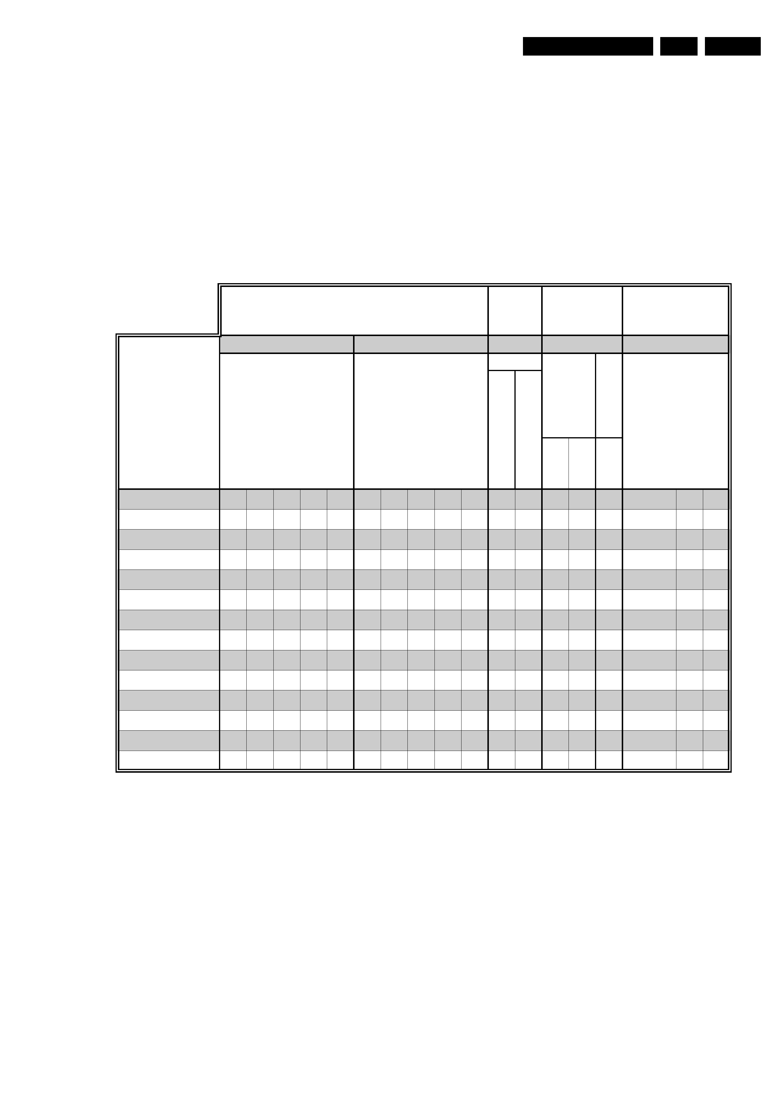
List of PWBs, Features, Technical specifications
1.1
Survey of sets and PWB's with software versions
AIO-µP
Pos.
7899
TAPE DECK
31
37
A
SP1
0
QKP
21
QBOG1
VT-MX100ECT
áá
á
á
á
VT-MX100EUK
ááá
á
á
VT-MX102EL
áááá
ááááá
á
á
VT-MX105EVPS
áá
á á
á
á
VT-MX110EUK
áá
á á
á
á
VT-MX130EVPS
áá
á á
á
á
VT-MX132EL
áááá
ááááá
á
á
VT-FX140ELN
áááá
ááááá
á
á
VT-FX140ENA
áá
á á
á
á
VT-FX140EUKN
áá
á á
á
á
VT-FX140EVPS
áá
á á
á
á
VT-FX145ENAV
áá
á á
á
áá
VT-FX152ELN
áááá
ááááá
á
áá
á
VT-FX162ELN
áááá
ááááá
á
áá
S
E
CAM
Pb
N
T
SC
on
PA
L
TV
µP-ID No.
chinch print
shuttle print
chapter 10
chapter 7
MESEC
A
M
P
b
Bl
ack
&
Whi
te
Mobo
Rec/Pb standard
SYSTEMS
System off air
PA
L
B
G
S
E
CAM
BG
P
A
L
/S
E
CAM
DK
PA
L
PA
L
I
SEC
A
M
L/L
'
A12T-P
2/
0LP
AT
-S
4/
2
A12T-P
2/
0
AT
-S
4/
0
shuttl
e
print
cinch
print
AC3P1
-
xU
AC3P7
-
xU
List of PWBs, Features, Technical specifications
GB 4
VT-MX100E
1.
1.2
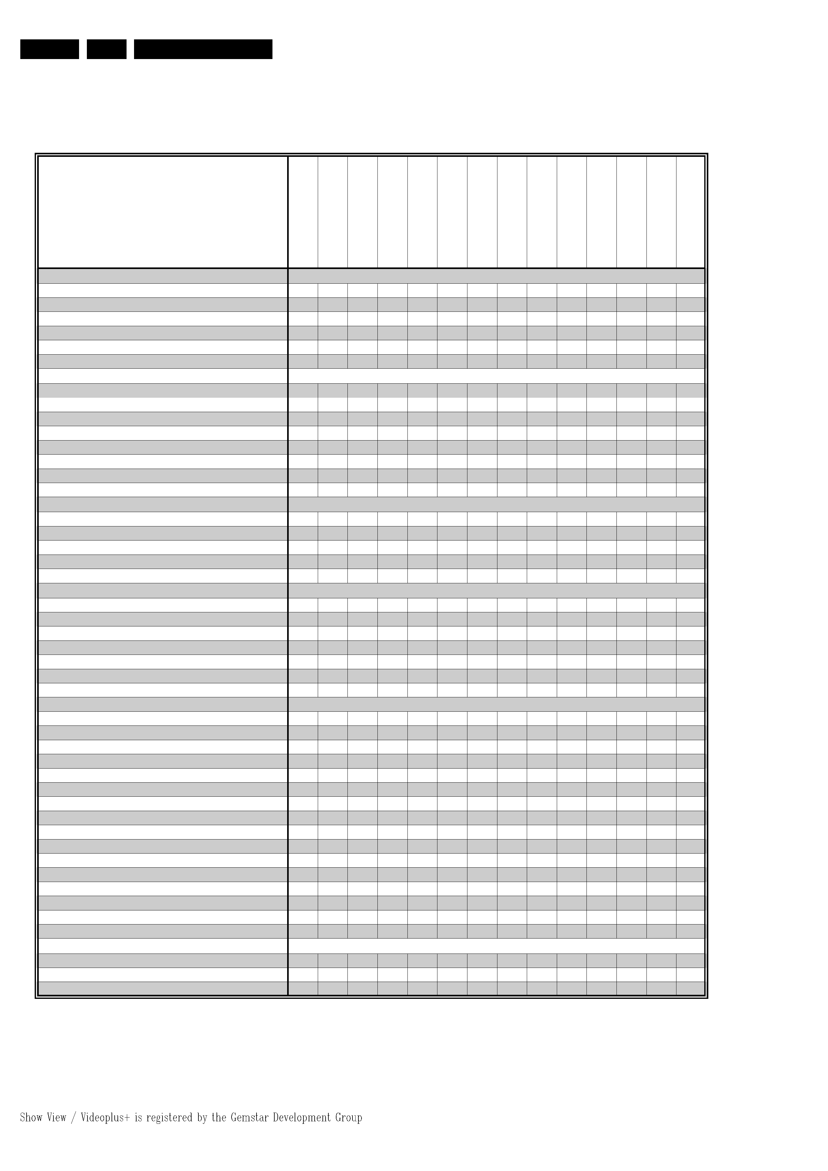
Features
VT
-M
X100ECT
VT
-M
X100EUK
VT
-M
X102EL
VT
-M
X105EVPS
VT
-M
X110EUK
VT
-M
X130EVPS
VT
-M
X132EL
VT
-F
X140EL
N
VT
-F
X140ENA
VT
-F
X140EUKN
VT
-F
X140EVPS
VT
-F
X145ENAV
VT
-F
X152EL
N
VT
-F
X162EL
N
General
Auto Standby On/Off
áááááááááááááá
Backup Presets 1yr
áááááááááááááá
Backup Clock / Timer 3hrs
áááááááááááááá
Number of Events / month
66666666666666
Low Power Standby Power Cons.
<4W <4W <4W <4W <4W <4W <4W <4W <4W <4W <4W <4W <4W <4W
Tuning - presets
99
99
99
99
99
99
99
99
99
99
99
99
99
99
Systems
Hyperband
á
áááááááááááá
UHF
áááááááááááááá
VHF
á
áááááááááááá
German Stereo
ááááááá
Mono
áááááááááááááá
NICAM
ááá
ááá
Splitter
áá
á
á
á
Auto Seek
áá
Mechanism
Number of Video Heads
22222444444444
Number of FM Heads
2222222
Head Cleaning Mode / automatic
áááááááááááááá
Tape Counter Linear Relative (h.m.s)
áááááááááááááá
Tape Counter
Time Left (h.m)
áááááááááááá
Features
Plug & Play
áááááááááááá
OSD
áááááááááááá
Auto Install/search/Store/Tuning
áááááááááááááá
NexTView Link (Rel 1.3)
áááááááááááá
Follow TV
áááááááááááá
Direct Record
áááááááááááá
Digital Studio Picture Control
áááááááááááááá
Tape Finder
VISS: next/prev. index
áááááááááááááá
blank tape search
áááááááááááááá
Commercial Skip
áááááááááááá
Easy Timer (Turbo Timer)
ááá
Easy View (Quick View)
áááááááááááááá
Daily/Weekly
áááááááááááá
Showview
áá
áááá
áááá
VideoPlus+
áá
VPS + PDC (VPD)
áááááááááááá
Time/Date download
áááááááááááá
Child Lock
áááááááááááááá
OTR
áááááááááááááá
Long Play
á
áááááááááá
Welcome Screen
áááááááááááá
Tape List
ááá
Tape Position Indicator
áááááááááááá
Connectors
Number of Scart connectors
11222222222222
Audio cinch rear
ááááááá
Audio / Video in cinch front
ááá

List of PWBs, Features, Technical specifications
GB 5
VT-MX100E
1.
1.3
Technical specification
Mains voltage
: 220 - 240 V, +/- 10%
Mains frequency
: 45 - 65 Hz
Power consumption
: mono 12.5 W during
operation
: HiFi
16 W during
operation
without Low Power Standby
: mono 4 W
during
standby
: HiFi 4.4 W during
standby
with Low Power Standby
: <
4 W standby
Ambient temperature
: +10°C to +35°C
Relative humidity
: 20 - 80 %
Dimensions
: 380 x 260 x 94 mm
Weight
: 3,7 kg
Fast forward/rewind time (turbo)
: typ. 100s (E180
cass.)
Position of use
: horizontally, max.
15°
Video resolution
:
240 lines
Audio SP: Linear Audio
: 80Hz - 10kHz (
±6
dB)
Audio LP: Linear Audio
: 80Hz - 5kHz (
±6
dB)
Stereo FM Audio
: 20Hz - 20kHz
(
±3dB)
Euroconnector (AV1) SCART plug 1
Connection to TV, monitor, projection TV ...
Pin 1
ARO (audio right out) 500 mVrms +/- 3 dB Rout
1kOhm
Pin 2
ARI (audio right in)
0,2 Vrms to 2Vrms
Rin
10 kOhm
Pin 3
ALO (audio left out)
500 mVrms +/- 3 dB Rout
1kOhm
Pin 6
ALI (audio left in)
0,2 Vrms to 2 Vrms
Rin
10 kOhm
Pin 7
Blue (out) **)
Pin 8
Switching output:
(with Rload = 10kOhm, Cload<2nF)
low: 2 V
high: 9.5 V
rise time: 5 ms
Pin 11 Green (out) **)
Pin 15 Red (out) **)
Pin 16 Blanking (out) **)
loop through enabled during
standby, view-mode
Pin 19 CVBS II (video out)
1 Vpp +1/-2dB
Rout 75 Ohm
Pin 20 CVBS I (video in)
1 Vpp +3/-3dB
Rin
75 Ohm
**) passive loop through from AV2
Euroconnector (AV2) SCART plug 2
Connection to decoder, SAT tuner, video disc, 2nd VCR ...
Pin 1
ARO (audio right out) 500 mVrms +/- 3 dB Rout
1kOhm
Pin 2
ARI (audio right in)
0,2 Vrms to 2Vrms
Rin
10 kOhm
Pin 3
ALO (audio left out)
500 mVrms +/- 3 dB Rout
1kOhm
Pin 6
ALI (audio left in)
0,2 Vrms to 2 Vrms
Rin
10 kOhm
Pin 7
Blue (out) **)
Pin 8
Switching input only:
low: 2 V (low)
Rin
10 kOhm
high: 4.5 V (high)
Rin
10 kOhm
Pin 11 Green (in) *)
Pin 15 Red (in) *)
Pin 16 Blanking (in) *)
loop through enabled during
standby, view-mode
Pin 19 CVBS II (video out)
1 Vpp +1/-2dB
Rout 75 Ohm
Pin 20 CVBS I (video in)
1 Vpp +3/-3dB
Rin
75 Ohm
*) passive loop through to Euroconnector AV1
Cinch Audio/Video input on front panel (OPTION)
Audio:
AINFR (audio right in) red
0.2 Vrms to 2 Vrms
typ. 500 mVrms
AINFL (audio left in) white 0.2 Vrms to 2 Vrms
typ. 500 mVrms
Input impedance
47 kOhm
Video:
VFR yellow
1 Vpp + 3 / -3 dB
Input impedance
75 Ohm
Cinch Audio Out Rear (OPTION)
AOUT1R (audio right out) red
500 mVrms +/- 3 dB Rout 1 kOhm
AOUT1L (audio left out) white
500 mVrms +/- 3 dB Rout 1 kOhm
This outputs are in parallel with the corresponding outputs on
Euroconnector 1.
TUMOD
Modulator:
Frequency range loop through
45 MHz - 860 MHz
Gain:
ANT IN - TV OUT
2 dB + 3 / -2 dB
ANT IN - TUN OUT
2 dB + 3 / -2 dB
Switch for RF input attenuation
NO
Frequency range out (tuned by IIC bus)
Ch 21 - Ch55
Tuner:
Frequency range
43 MHz - 860 MHz
for UK
450 MHz - 860MHz
Input voltage
max.
< 100 dB
µV
min.
> 60 dB
µV