1
HITACHI VT F645
General Information
Also Covers
VT F560, VT F660.
Recommended Safety Parts
Item
Part No.
Description
C0851
AN10201S
FILM CAPACITOR 0.1UF+-20% 250V
C0852
AN10201S
FILM CAPACITOR 0.1UF+-20% 250V
C0853
0235993
CERAMIC CHIP 220PF+-20% 250V
C0855
AJ10294
CERAMIC CAPACITOR 4700PF+-20% 125V
C0856
0235993
CERAMIC CHIP 220PF
±-20% 250V
C0858
0235993
CERAMIC CHIP 220PF
±-20% 250V
C0860
AJ10294
CERAMIC CAPACITOR 4700PF+-20% 125V
C0861
0235993
CERAMIC CHIP 220PF+-20% 250V
PC0851
CF10431G
PHOTO COUPLER PC123FY
QF0851
5721945
IC PROTECTOR, ICP--N38
QF0852
5721946
PROTECTOR, ICP--N15
QF0853
5721944
IC PROTECTOR, ICP--N25
QF4501
5721941
IC PROTECTOR, ICP--N5
T0851
BT10282
TRANSFORMER POWER (HEPM)
L0851
BV10241
FILTER, LINE 18MH
F0851
5723351
FUSE
FH0851
5722412
HOLDER, FUSE
FH0852
5722412
HOLDER, FUSE
101
QA11514
COVER, TOP
[6U,6N]
101
QA11931
COVER, TOP (HEPM)
[EXCEPT 6U,6N]
102
PH15251
PANEL, FRONT (HEPM)
[6U]
102
PH15253
PANEL, FRONT (HEPM)
[6N]
102
PH15541
PANEL, FRONT (HEPM)
[4U]
102
PH15542
PANEL, FRONT (HEPM)
[4N]
102
PH15543
PANEL, FRONT (HEPM)
[5U]
102
PH15544
PANEL, FRONT (HEPM)
[1,2 MN MV]
105
PC11912
KNOB, SHUTTLE (HERM)
[5U, 1, 2, MN, MV]
106
NT10483
PIECE, FRONT (HEPM)
[EXCEPT 6U, 6N]
106
NT10733
PIECE, FRONT (HEPM)
[6U, 6N]
107
PH13321
DOOR CASSETTE (HEPM)
[EXCEPT 6U, 6N]
107
PH15561
DOOR CASSETTE (HEPM)
[6U, 6N]
108
KL11451
SPRING, DOOR (HEPM)
[EXCEPT 6U, 6N]
108
KL11522
SPRING, DOOR (HEPM)
[6U, 6N]
111
EV10541
AC CORD (HEPM)
[EXCEPT 4U, 5U, 6U]
111
EV10551
CORD, POWER (HEPM)
[4U, 5U, 6U]
115
M010199
CUSHION, RUBBER
[EXCEPT 6U, 6N]
117
0A11151
COVER, BOTTOM (HEPM)
[EXCEPT 6U, 6N]
117
0A11911
COVER, BOTTOM (HEPM)
[6U, 6N]
118
MD11281
COVER, CBA
119
PH13721
PANEL, REAR (HEPM)
[EXCEPT 6U, 6N]
119
PH15361
PANEL, REAR (HEPM)
[6U, 6N]
125
6810651
HOLDER, CBA
126
MN12251
SHEET, INSULATE (HEPM)
127
MD11661
SHEET, SHIELD (HEPM)
130
PC12562
RING, SHUTTLE
[6U, 6N]
131
PC12572
DIAL, JOG
[6U, 6N]
135
NA13982
BRACKET CBA
[6U, 6N]
139
4826834
SPRING, EARTH
203
KX11661
CLEANING, HEAD
205
GP10252
MOTOR, CAPSTAN
206
KX12294
BASE, GUIDE ROLLER (I)
210
KX12302
BASE, GUIDE ROLLER (O)
212
KX11531
ARM, TENSION
213
KL10662
SPRING
214
KX11631
BAND, TENSION
215
KF10641
GEAR, DRIVE
216
KF10701
GEAR, IDLER
217
KX12661
ARM, OUT
218
KX11581
GEAR, SPIRAL
219
KX11553
ARM, PINCH ROLLER
220
KX11451
BASE, CYLINDER
221
KX11941
AC HEAD
223
5423082
FE HEAD
224
KL10711
SPRING
225
KX11591
GEAR, LOADING (L)
226
KX11611
GEAR, LOADING (R)
227
KF10673
GEAR, CAM
228
4344643
WASHER
229
KX11443
PULLEY
230
KX11522
BELT
231
KF10631
FLANGE
232
KX12031
BRAKE
233
KF10571
GEAR, CHANGE
234
KL10771
SPRING
235
KX12001
STOPPER, SPRING
236
KF10561
GEAR, IDLER
237
KX11831
ARM, OPERATION
238
KX11362
SLIDER
239
KF10551
GEAR, TRANS
240
KF1O5O1
GEAR, DRIVE
241
KL10773
SPRING
242
KF10513
GEAR, CHANGE
243
KX11411
ARM, CHANGE
244
KX11371
GEAR
245
KX11892
MOTOR, LOADING
246
KF10521
GEAR, IDLER 1
247
KF10532
GEAR, IDLER 2
248
KH10152
REEL, TABLE (S)
249
KX11423
ARM
250
KH10161
REEL, TABLE (T)
251
KX11991
STOPPER
252
KX11861
BRAKE
253
KL10782
SPRING, BRAKE
254
KX11875
BRAKE, L
255
KX11883
BRAKE, R
256
KL10792
SPRING, BRAKE
257
KF10542
GEAR, JOG
258
KX13132
ARM, JOG
259
KX11841
ARM, REC
260
6542482
SPRING
261
KX11811
BRAKE, SUB
262
KL10903
SPRING, SUB
263
KX12461
BRACKET, BASE
264
MN11571
WASHER
265
KL11062
SPRING, JOG
401
KX11772
BRACKET (R)
402
KF10682
GEAR 1
403
KF10691
GEAR 2
404
KX11751
ARM, DOOR
405
KX11761
ARM, SWITCH
406
6323723
SPRING
407
KX11931
ARM, DRIVE
408
KX11921
HOLDER, CASSETTE
409
KX11741
BRACKET(L)
501
5435721
CYLINDER UPPER
(CY-G651)
502
5435711
CYLINDER ASSY
(CY-G651)
901
8699412
SCREW (3X12) BLACK
902
8679408
SCREW (3.0X8)
[EXCEPT 6U, 6N]
902
MK10271
SCREW(3X12DT)
[6U, 6N]
903
8671306
SCREW(2.6X6)
904
7781132
BT SCREW
905
7784323
SCREW (3X8)
906
8699410
SCREW (3X10)
951
8652408
SCREW (PSW3X8)
952
0671310
DT SCREW -2.6MMDX10MM
953
0671306
DT SCREW 2.6MMDX6MM
954
8691306
BT SCREW 2.6MM
956
KX12443
SCREW
957
MJ10341
SCREW(M2.6)
958
0671308
DT SCREW -2.6MMDX8MM
959
0671305
DT SCREW -2.6MMDX5MM
802
HL10374
REMOTE HAND SET
(VT-RM453E) (HEPM) [6U]
802
HL10375
REMOTE HAND SET
(VT-RM454E) (HEPM) [6N]
802
HL10663
REMOTE HAND SET
(VT-RM650E) (HEPM) [4U, 5U]
802
HL10664
REMOTE HAND SET
(VT-RM655E) (HEPM) [1, 2, MN, MV, 4N]
803
5858315
CABLE (HEPM)
Mechanical Parts
Item
Part No.
Description
Mechanical Parts
Item
Part No.
Description
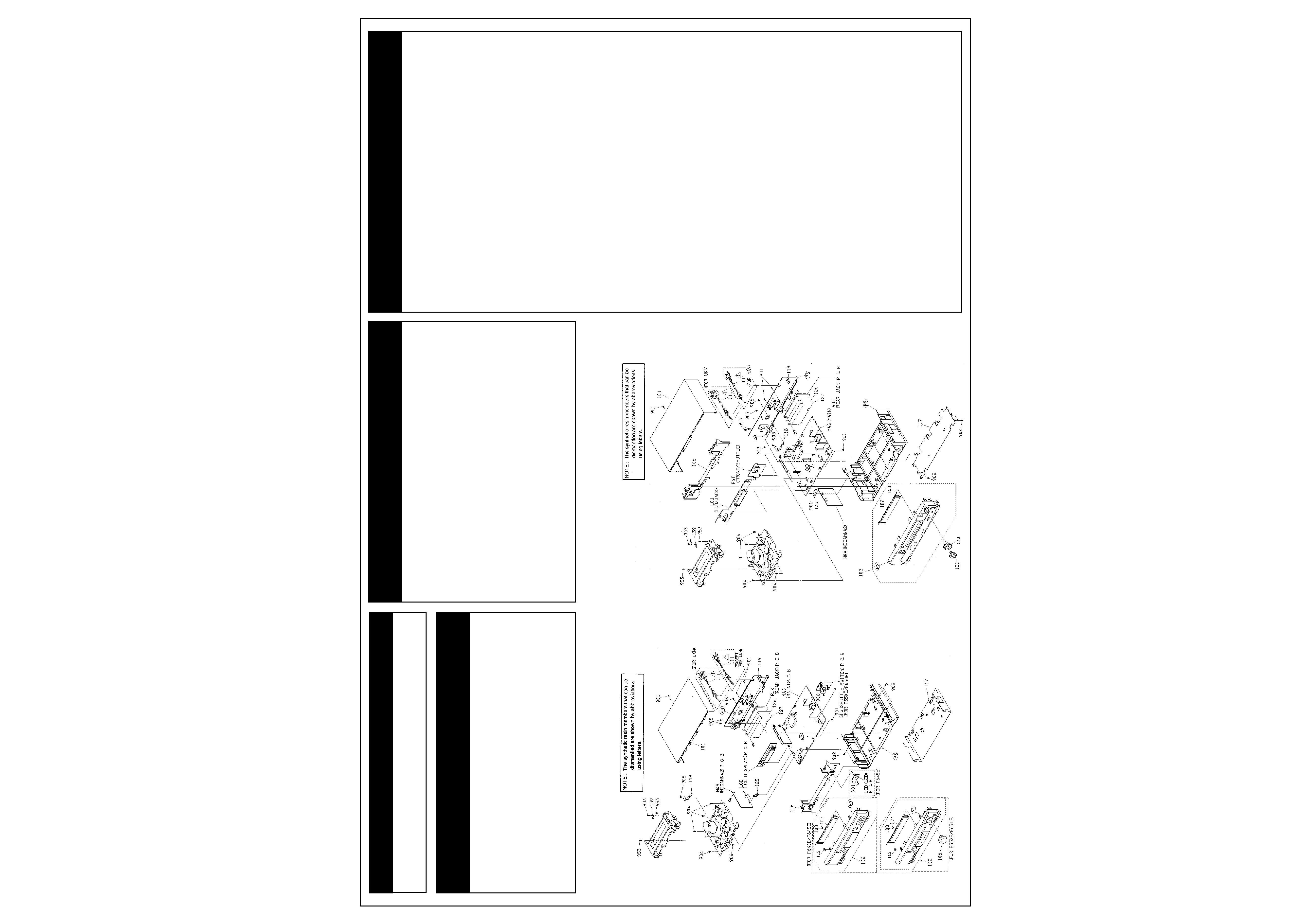
Exploded Parts Views
Continues next page.
2
HITACHI VT F645
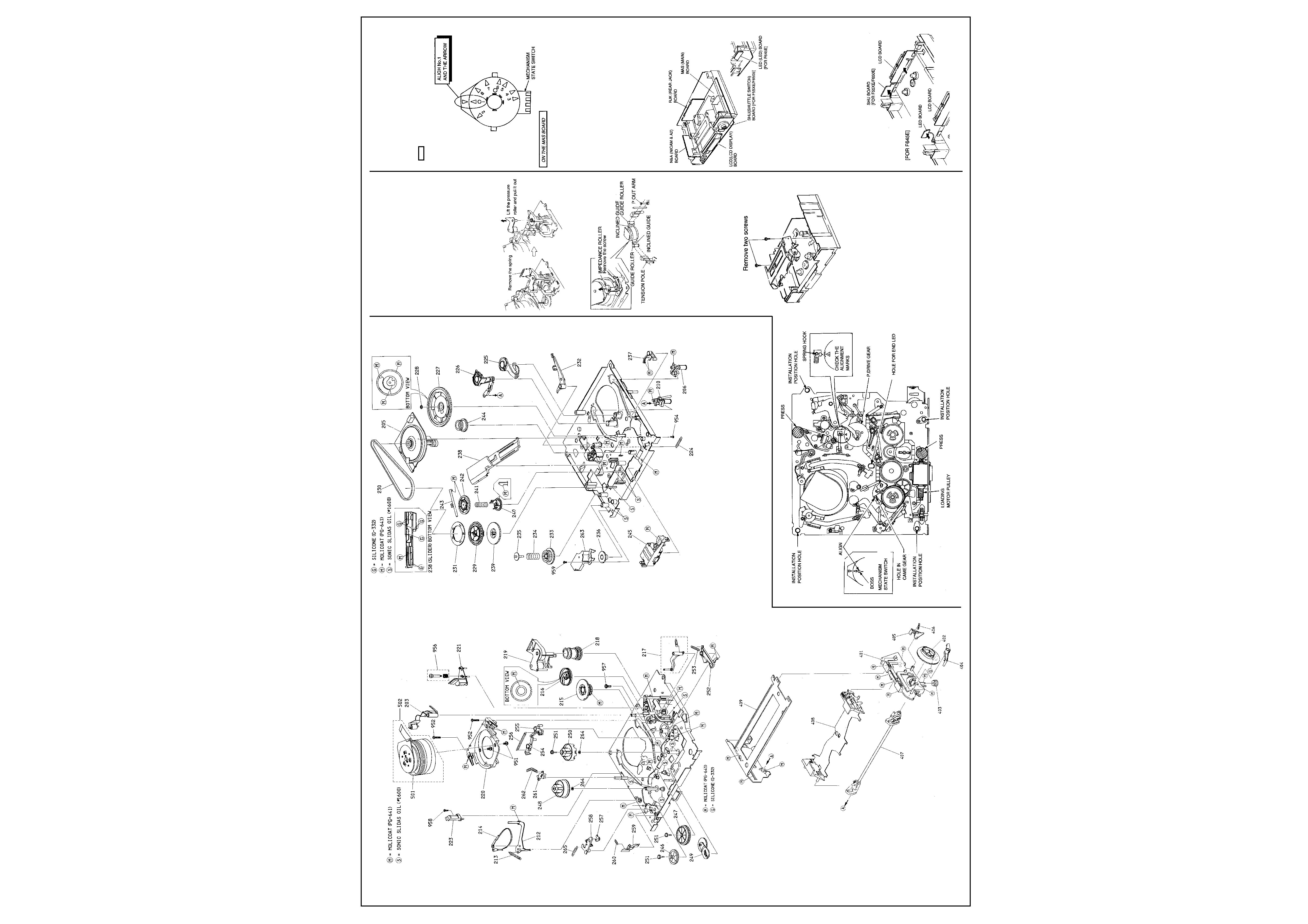
Exploded Parts Views Cont'd
How to Remove the Cassette when a Malfunc-
tion Has Occurred in the Mechanism
If a cassette is caught in the mechanism
because of a malfunction in the mechanism,
remove it by the following procedure.
(Work Procedure)
1. Remove the top cover.
2. Remove the front panel.
If the tape is wound round the cylinder in the
loading state
Remove the spring and lift the pressure roller to
pull it out.
Slacken the tape and release it from the tension
pole, guide rollers, inclined guides and P out
arm.
If the cassette dose not come out from the FL
mechanism in the unloading state.
1) Remove two screws holding the FL mecha-
nism.
2) Hold the cassette lid with your fingers so the
tape is not damaged and remove the FL
mechanism.
3) Remove the slack tape and eject the cas-
sette.
Caution When Reinstalling the US Mecha-
nism
This VCR has mechanism sensors on the MAS
board and the capstan and loading motors are
connected via direct connectors. Therefore,
when reinstalling the US mechanism, observe
the following cautions.
1) Align the w mark and mode no. 1 of the
mechanism state switch on the MAS board.
(Mode no. 1 of the mechanism state switch
has a click position.)
2) Check that mode no. 1 on the P drive gear in
the mechanism and the w mark of the spring
hook are aligned. If they are not aligned, turn
the loading motor pulley to align them.
3) Pass the end LED through the hole in the
mechanism and install the mechanism from
immediately above using the installation
position holes as reference. Check that the
boss of the mechanism state switch and the
hole in the cam gear are aligned.
4) Push the terminal sections (shaded sections
) of the capstan and loading motors and
check that they are inserted securely.
Fig. 2-17
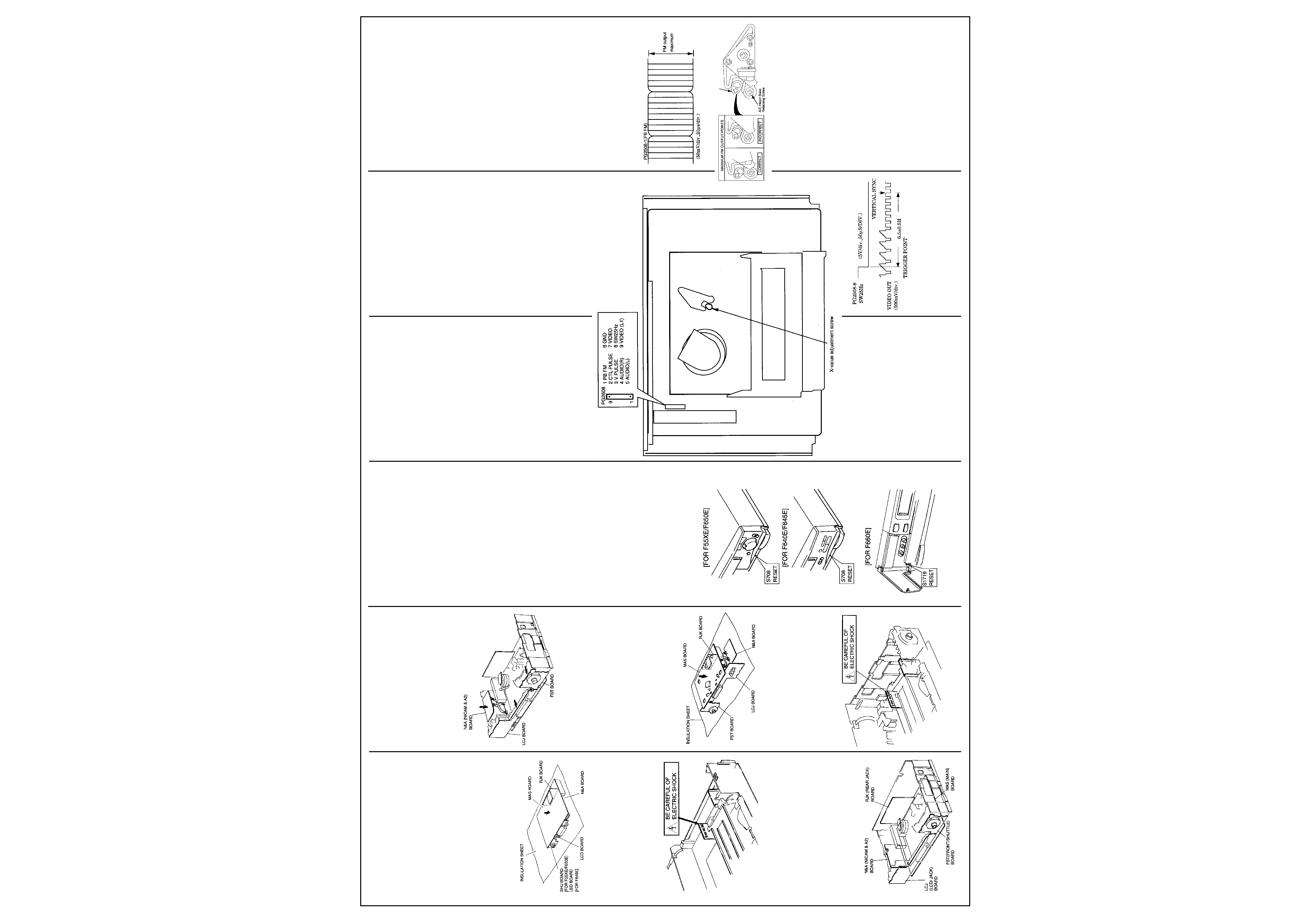
ELECTRIC CIRCUIT ADJUSTMENT AND
TROUBLE DISPLAY
Service Position
(VT-F55XE/F640E/F645E/F650E)
1. Servicing position during electrical
adjustment
Perform adjustment after removing the top
cover, front panel and rear panel. When the
shield cover of the connector between the
cylinder motor and MAS circuit boards is
removed, noise appears in the played back
picture. Attach the shield cover when checking
the picture on the screen.
Fig. 1
2. Servicing positions when repairing and
checking circuits
2-1. Procedure to set the SHU, EST or LED
and LCD or LCJ boards to the servicing
positions (Fig. 2)
1) Remove the top cover and front panel.
2) Remove the US-FL mechanism.
3) Remove the SHU or LED and LCD boards
and front frame, then reattach the SHU or
LED and LCD board.
Fig. 2
Mechanical Adjustments
1234
1234
1234
Fig. 2-18
3
HITACHI VT F645
2-2. Procedure to set the MAS board to the
servicing position (Fig. 3)
1) Remove the top cover, front panel and rear
panel.
2) Remove the US-FL mechanism and front
frame.
3) Remove the MAS board, with the LCD and
SHU or LED, N&A and RJK boards and US
mechanism assembled from the frame.
4) Turn over the MAS board and perform checks
from the pattern side indicated by the arrow.
Be careful of the following at this time. Lay out
an insulation sheet under the boards. Attach the
shield cover at the rear of the cylinder. Attach
the US-FL mechanism when loading the tape.
Fig. 3
3. Be careful of electric shocks
The power supply block on the right of the VCR
has a heat sink which generates a high voltage.
`HIGH VOLTAGE' is printed on the heat sink.
Take great care when handling this heat sink
when the power is turned on during servicing.
Fig. 4
Service Position (VT-F660E)
1. Servicing position during electrical
adjustment
Perform adjustment after removing the top
cover, front panel and rear panel.
When the shield cover of the connector between
the cylinder motor and MAS circuit boards is
removed, noise appears in the played back
picture. Attach the shield cover when checking
the picture on the screen.
Fig. 1
2. Servicing positions when repairing and
checking circuits
2-1. Procedure to set the LCJ, FST and N&A
boards to the servicing positions (Fig. 2)
1) Remove the top cover, front panel and rear
panel.
2) Remove the US-FL mechanism.
3) Remove the front frame and open each board
as shown in the diagram below and perform
check from the patterm side (indicated by the
arrow).
Fig. 2
2-2. Procedure to set the MAS board to the
servicing position (Fig. 3)
1) Remove the top cover, front panel and rear
panel.
2) Remove the US-FL mechanism and front
frame.
3) Remove the MAS board, with each board and
the US mechanism assembled on it, from the
frame.
4) Turn over the MAS board and perform checks
from the pattern side (indicated by the arrow).
Take care of the following at this time. Lay the
insulation sheet under the boards. Attach the
US-FL mechanism when loading a tape.
Fig. 3
3. Be careful of electric shocks.
The power supply block on the right of the VCR
has a heat sink which generates a high voltage.
"HIGH VOLTAGE" is printed on the heat sink.
Take great care when handling this heat sink
when the power is turned on during servicing.
Fig.4
Electrical Adjustments
1. Test equipment/jigs necessary for adjust-
ment
1) Dual-trace oscilloscope
2) Colour bar generator
3) Voltmeter
4) Monitor TV (with A/V jacks)
5) Alignment tapes:
MH-2: Part No. 7099052
24HMAF-2: Part No. 7099175
(Hi-Fi alignment tape)
6) Blank tape
7) C/R oscillator
2. Caution on adjustment
1) The following conditions apply when other-
wise not specified.
Probe of oscilloscope: 10:1
Synchronization of oscilloscope: Internal sync
Ground of test equipment: PG2508 pin 6 (on
MAS board)
2) When performing more than one adjustment,
follow the specified order.
3. Tips for adjustment
3-1 Procedure to reset the main microproc-
essor
The main microprocessor is not reset even
when the power cord is unplugged from the AC
outlet because its power is backed up by a
backup circuit. Press S708 on the MAS board to
reset the entire microprocessor. Do not press
the reset switch with the power cord unplugged
from the AC outlet as the slow tracking preset
value could drift. If the preset value drifts, plug
the power cord into an AC outlet and press the
reset switch again with the power turned on. It is
recommended that you press the reset switch
after reinstalling the front panel.
Fig. 5
3-2. Procedure to switch off the blue back-
ground function
1) Press the "GUIDE" button of the remote
control to display the menu on the monitor TV
screen.
2) Press 2 to select the VCR setup screen.
3) Press 1 to specify blue background off.
3-3. Procedure to obtain the LP head play-
back mode (X-value adjustment test mode)
Press the TRACKING UP (v) and DOWN (w)
buttons of the remote control provided simulta-
neously when an alignment tape is being played
and hold them, then press the "CHANNEL w"
button on the VCR; The VCR enters the LP head
playback mode (X-value adjustment test mode).
4. Connections of test equipment
Connect the test equipment as follows when
otherwise not specified.
1) Connect a colour bar generator to the video
input jack of the VCR.
2) Connect a monitor TV to the Euro Socket of
the VCR.
3) Connect an antenna to the antenna jack and
receive a TV broadcast (only for sound
multiplex adjustment).
Test and Adjustment Points
Fig. 6 MAS (Main) Circuit Board
[Components Side]
5. Servo Circuit Adjustments
5-1. Switching point adjustment (Fig. 6)
Purpose:
To set the switching point of the video heads
during playback to the center where the CH-1
and CH-2 envelopes overlap each other.
Fault due to incomplete adjustment:
Vertical sync signal is degraded and vertical
jitter occurs.
Switching noise appears across the bottom of
the screen.
Test Equipment/Jigs
Oscilloscope
Alignment tape (MH-2)
Connection Points
CH-1: Video out jack
CH-2: PG2508-8(SW25Hz)
State of VCR
1) Play the alignment tape
2) Set to the X-value adjustment test mode.
Adjustment Point
F.FWD button (S702)
REW button (S703)
Adjustment Procedure
1) Play the alignment tape.
2) Press the tracking up (v) and down (w)
buttons of the remote control provided
simultaneously and hold them, then press the
"CHANNEL w" (S707) button of the VCR to
set the VCR to the test mode. (SP is switched
to LP in the display.)
3) Press the "F.FWD"and "REW" buttons of the
remote control so the phase from the vertical
sync to the trailing edge (trigger position) of
the SW25Hz pulse is set to 6.5H + 0.5H.
4) Press the STOP button to release the test
mode.
-conditions of oscilloscope-
Trigger with CH-2. Set the sync slope to "-".
played back, the tracking is not optimized and
noise appears on the screen.
Test Equipment/Jigs
Oscilloscope
Alignment tape (MH-2)
Connection Points
CH-1: PG2508-1 (PB FM)
CH-2: PG2508-8 (SW25Hz)
State of VCR
1) Play the alignment tape.
2) Set to the X-value adjustment test mode.
Adjustment Point
Groove for the adjustment X- value
Adjustment Procedure
1) Play the alignment tape.
2) Press the tracking up (v) and down (w)
buttons of the remote control provided
simultaneously and hold them, then press the
"CHANNEL w" (S707) button of the VCR to
set the VCR to the test mode. (SP is switched
to LP in the display.)
3) Loosen the screw holding the A/C head base
(do not loosen it excessively).
4) Insert a screwdriver into the groove for
adjusting the X-value and adjust so the FM
output is maximum. There are two maximum
FM output points when the groove for
adjusting the X-value is turned. Adjust the FM
output to a maximum when the groove is at
the correct position as shown in the figure
below.
5) Press the STOP button to release the test
mode.
Waveforms
Groove for Adjustment the X-Value
5-3. Vertical jitter adjustment
Purpose:
To suppress vertical jitter during slow and still
play.
Fault due to incomplete adjustment:
Vertical jitter appears in the picture during slow
and still play.
Test Equipment/Jigs
Monitor TV
Colour bar generator
Blank tape
Connection Points
Video output jack
Video input jack
State of VCR
Record a colour bar signal and play it using the
same VCR.
Adjustment Point
Tracking up
Tracking down
Mechanical Adjustments
Cont'd
Waveforms
5-2. X-Value Adjustment (Fig. 6)
Purpose:
To ensure compatibility with other VCRs.
Fault due to incomplete adjustment:
When a tape recorded by another VCR is
4
HITACHI VT F645
Adjustment Procedure
<LP vertical jitter correction>: Record in the LP
mode and play it back using the same VCR.
1) Press the PAUSE button to set the VCR to
the still play mode.
2) Use the tracking up or down buttons of the
remote control to suppress vertical jitter of the
picture.
<SP vertical jitter correction>: Record in the SP
mode and play it back using the same VCR.
1) Press the PAUSE button to set the VCR to
the still play mode.
2) Use the tracking upn or down buttons of the
remote control to suppress vertical jitter in the
picture.
5-4. Forward slow tracking preset adjustment
Purpose:
To adjust the timing with which the brake pulse
of the capstan motor is generated during slow
play so that noise is minimum.
Fault due to incomplete adjustment:
Noise appears during slow play and the picture
is not clear.
Test Equipment/Jigs
Monitor TV
Colour bar generator
Blank tape (E-180)
Connection Points
Video output jack
Video input jack
State of VCR
Slow tracking: Unplug the power cord to set the
slow tracking to the center.
Adjustment Point
Tracking up
Tracking down
Adjustment Procedure
1) Record a signal on the middle of a E-180
blank tape in the LP mode and play it back
using the same VCR.
2) Press the tracking up and down buttons of
the remote control (provided) simultaneously
during playback and hold them, then press
the "PLAY" button (S701) to set the VCR to
the forward test slow mode.
3) Press the tracking up or down buttons so the
slow feed noise appears across the bottom of
the monitor screen and then it is driven out
from the bottom of the screen.
4) Check that no noise appears on the monitor
screen.
5) Press the "PLAY" button to return the VCR to
the playback mode (the preset data is written
to the EEPROM).
6) Perform the same procedure to perform slow
tracking preset adjustment in the SP mode.
Do not press the reset switch after adjustment
when the power is not turned on as the preset
value could drift. If the preset value drifts, turn
the power on and press the reset switch again
for recovery.
5-5. Reverse slow tracking preset adjustment
Purpose:
To adjust the timing with which the brake pulse
of the capstan motor is generated during
reverse slow play so that noise is minimum.
Fault due to incomplete adjustment:
Noise appears during reverse slow play and the
picture is not clear.
Test Equipment/Jigs
Monitor TV
Colour bar generator
Blank tape (E-180)
Connection Points
Video output jack
Video input jack
State of VCR
Slow tracking: Unplug the power cord to set the
slow tracking to the center.
Adjustment Point
Tracking up
Tracking down
Adjustment Procedure
1) Record a signal on the middle of a E-180
blank tape in the LP mode and play it back
using the same VCR.
2) Press the tracking up and down buttons of
the remote control (provided) simultaneously
during still and hold them, then press the
"PLAY" button (S701) to set the VCR to the
forward test slow mode.
3) Press the tracking up or down buttons so the
slow feed noise appears across the bottom of
the monitor screen and then it is driven out
from the bottom of the screen.
4) Check that no noise appears on the monitor
screen.
5) Press the "PLAY" button to return the VCR to
the playback mode (the preset data is written
to the EEPROM).
6)Perform the same procedure to perform slow
tracking preset adjustment in the SP mode.
Do not press the reset switch after adjustment
when the power is not turned on as the preset
value could drift. If the preset value drifts, turn
the power on and press the reset switch again
for recovery.
6. Audio Circuit Adjustment
6-1. Hi-Fi audio Dlavback level check
Purpose:
To set the playback level of the Hi-Fi audio
signai to the specified value.
Fault due to incomplete adjustment:
The appropriate volume cannot be obtained
during playback.
Test Equipment/Jigs
Voltmeter
Hi-Fi Alignment tape (24HMAF-2)
Connection Points
When checking R-CH: PG2508-4
When checking L-CH: PG2508-5
State of VCR
Play Hi-Fi alignment tape.
Adjustment Point
------------------------
Adjustment Procedure
Use the same checking procedure for both the L
and R channels. Check that the voltmeter reads
-7.8dBs
± 3.0dBs. If it cannot be confirmed,
check the playback signal system.
6-2. E-E audio level check
Purpose:
To check the audio level in the E-E mode.
Fault due to incomplete adjustment:
The sound is abnormal in the E-E mode.
Test Equipment/Jigs
C/R oscillator
Voltmeter
Connection Points
Audio in 1 jack (L-CH)
Audio in 1 jack (R-CH)
Audio out jack (L-CH)
Audio out jack (R-CH)
State of VCR
E-E mode
Adjustment Point
------------------------
Adjustment Procedure
1) Apply a 1kHz, -7.8dBs sinewave signal to the
audio input 1 (L-CH and R-CH) jacks.
2) Check that the voltmeter reads -9.8dBs
±
2.0dBs.
3) If the above cannot be confirmed, check the
E-E audio line.
List of Data in EEPROM and Initial Settings
The table below lists the data stored in ROM. It
also shows the data set by shipment mode
initialization, when the trouble display is cleared.
List of Hidden Commands
The following tables list the mode setting
commands during adjustment and EEPROM
initial setting commands.
2. EEPROM initialization commands
Electrical Adjustments
Cont'd
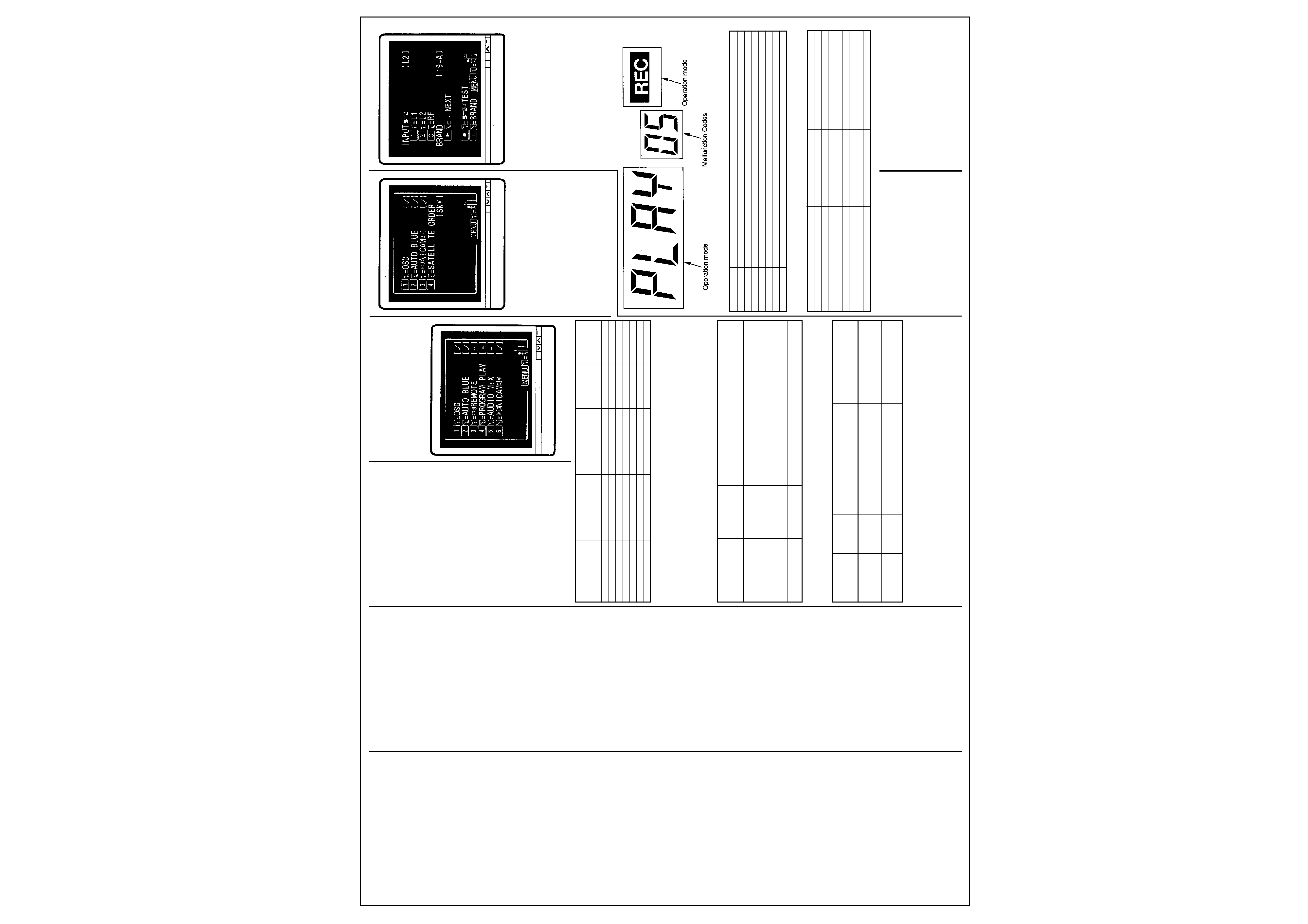
Initial Settings of IC903(EEPROM)
The following shows the on-screen display and
modes of switches when IC903 (EEPROM) is
initialized.
(A) VCR SET-UP MENU
[FOR F660E]
[FOR F55XE/F64XE/F650E]
Note:
(3) is for (UKN), (NA) & (NAV) only.
(4) is for (UKN) only.
Caution When Replacing IC903 (EEPROM)
After replacing IC903 (EEPROM), execute the
VCR initial settings and then perform the
following adjustments.
Adjustment
1 Switching point adjustment
2 Vertical jitter adjustment
3 Forward slow tracking adjustment
4 Reverse slow tracking adjustment
Data memory ROMs
List of initial data
Information
IC903
Shipment mode
clearing of
Remarks
EEPROM
initial data
trouble display
Channel memory
0
0
VCR mode select data
0
0
Trouble display data
0
0
0
Slow tracking data
0
X (set by adj.)
Artificial V sync data
0
X(set by adj.)
Switching point data
0
X (set by adj.)
SAT data
0
0
1. Mode setting commands during adjustment
Item
Mode in which
Operation
command is
accepted
Tracking center
Play
Press the tracking up and down buttons of the remote
control simultaneously.
X-value adjustment
Play
Press the tracking up and down buttons of the remote
test mode
control simultaneously and press the "CHANNEL w" button on the VCR.
Forward test slow mode
Play
Press the tracking up and down buttons of the remote
control simultaneously and press the "PLAY" button on the VCR.
Reverse test slow mode
Still play
Press the tracking up and down buttons of the remote
control simultaneously and press the "PLAY" button on the VCR.
Item
Mode in which
Operation
Remarks
command is
accepted
Shipment mode
Press the "REC" buttons on the VCR and hold it,
Hold the "REC" button depressed
initial setting
EJECT
then press the "RESET" button used to initialize
and release it after the display
the microprocessor.
lights.
Clearing of
Press the "PLAY" button on the VCR and hold it,
Hold the "PLAY" button depressed
trouble display
then press the "RESET" button used to initialize
and release it after the display
the microprocessor.
lights.
(B) SATELLITE SET-UP MENU
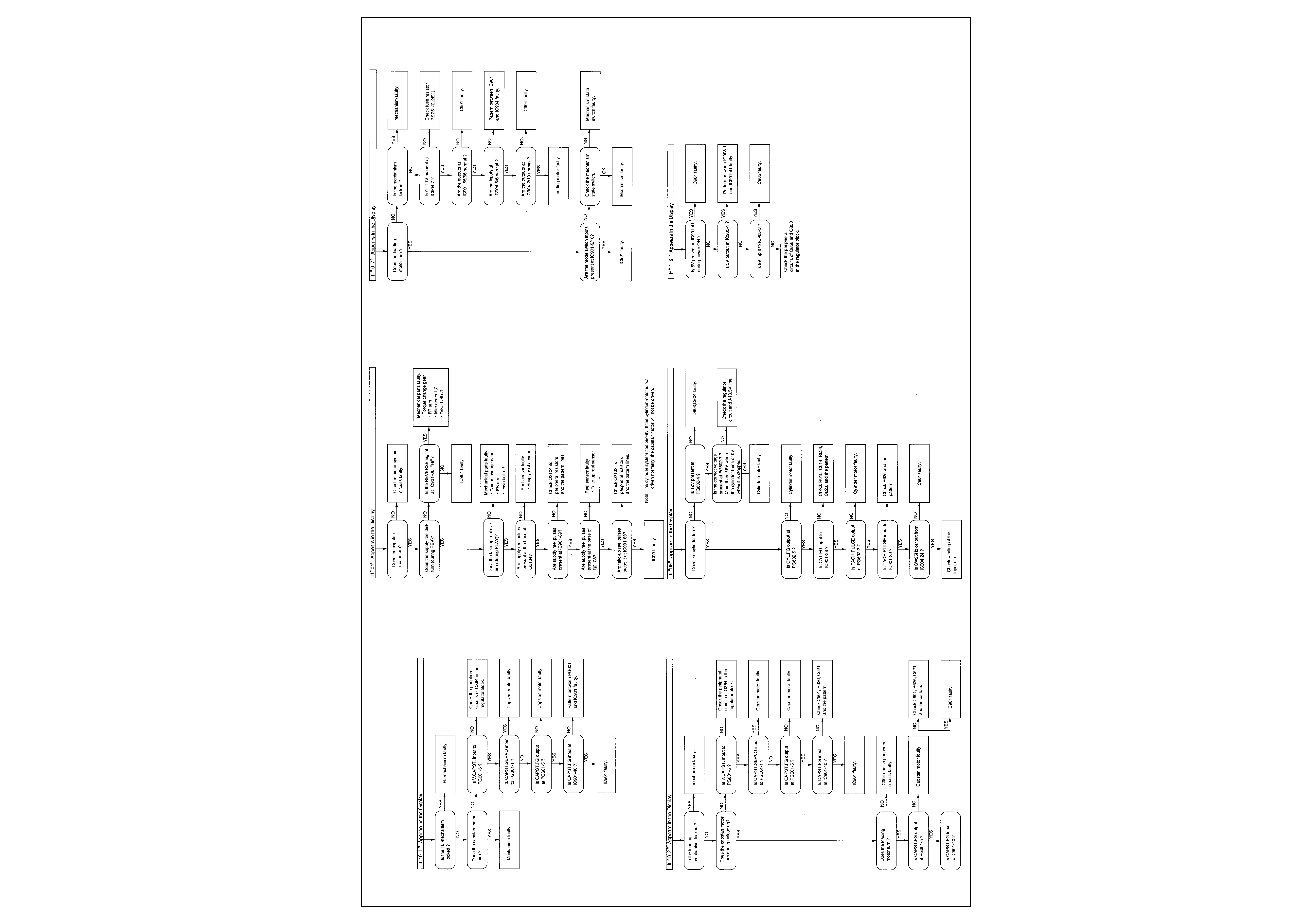
TROUBLE DISPLAY FUNCTION
This VCR has a function which displays
mechanism malfunctions, etc. in the LCD
display. Use this function to analyze the cause
when the power is shut off due to a malfunction,
etc. in the mechanism. Two types of information
are displayed, 1) The operation mode when the
malfunction occurred, 2) Malfunction Codes.
The details of the malfunction are displayed as
follows.
No symbols are displayed if the malfunction
occurred when a cassette was inserted or
ejected, or the power was switched on from off,
and off from on. Procedure to dis Ia a malfunc-
tion.
Procedure to display a malfunction
Press the (CH w) button on the VCR when the
power is turned off and hold it; the malfunction
[Display of details of malfunction]
Displayed No.
Item
Details
"0 0"
No malfunction
"0 1"
FL mechanism lock
Malfunction in insertion/ejection of cassette
"0 2"
Capstan lock
Malfunction of capstan motor drive during tape unloading
"0 4"
Reel lock
Reel rotation trouble when tape is running
"0 6"
Cylinder lock
Cylinder rotation malfanction
"0 7"
Loading mechanism lock
Malfunction in shifting mechanism mode
"1 6"
Servo lock
Shorting of 5V detected
[Mode Display when Malfunction Has Occurred]
Mode
Display
Mode
Display
Stop
No Display
Playback
P L A Y
Fast forward
F F
Reverse playback
-- P L A Y
Rewind
R E W
Forward search
S R C H
High speed fast forward
S : F F
Reverse search
-- S R C H
High speed rewind
S : R E W
Slow motion play
S L 0 W
Recording
REC
Reverse motion slow play
S L 0 W
Recording pause
REC (flashes)
Still motion play
S T I L L
code is displayed while the button is held
depressed.
Procedure to clear the malfunction display
Press the "PLAY" button on the VCR and hold it,
then press the microprocessor "RESET" button
to initialize the trouble display.
5
HITACHI VT F645
Fault Finding Guides