CAUTION:
Before servicing this chassis, it is important that the service technician read the "Safety
Precautions" and "Product Safety Notices" in this service manual.
ATTENTION:
Avant d'effectuer l'entretien du châassis, le technicien doit lire les «Précautions de sécurité»
et les «Notices de sécurité du produit» présentés dans le présent manuel.
VORSICHT:
Vor Öffnen des Gehäuses hat der Service-Ingenieur die ,,Sicherheitshinweise" und ,,Hinweise
zur Produktsicherheit" in diesem Wartungshandbuch zu lesen.
SERVICE MANUAL
MANUEL D'ENTRETIEN
WARTUNGSHANDBUCH
Data
contained
within
this
Service
manual is subject to alteration for
improvement.
Les données fournies dans le présent
manuel d'entretien peuvent faire l'objet
de modifications en vue de perfectionner
le produit.
Die
in
diesem
Wartungshandbuch
enthaltenen Spezifikationen können sich
zwecks Verbesserungen ändern.
FEBRUARY 2001
8mm VIDEO CAMERA/RECORDER
VMH775LE
VME578LEAU
VME578LESW
VME575LE
AC Adapter
VMACE5E
VMACE5EAU
SM7103
SPECIFICATIONS AND PARTS ARE SUBJECT TO CHANGE FOR IMPROVEMENT
When Servicing the Mechanism:
This camera/recorder uses a UH mechanism.
When servicing the UH mechanism, refer to the
following service manuals:
Item
Manuals to be referred to
Disassembly
UH Mechanism (No. 6811E)
Mechanical
UH Mechanism Supplement
Adjustment
(No. 6811E-1)
Maintenance/
Inspection
UH mechanism (No. 6811E)
Procedure
Exploded View
Chapter 4 in this manual

CONTENTS-1
CHAPTER 1
GENERAL INFORMATION
SPECIFICATIONS ..................................................... 1-1
COMPARISON OF FEATURES ................................ 1-2
COMPARISON OF MAIN CONTROL ICs ................. 1-4
JIGS AND TAPES FOR SERVICE ............................ 1-5
HOW TO USE THE EXTENSION CABLE AND JIG .. 1-6
SERVICE POSITION ................................................. 1-6
SERVICE MANUAL ABBREVIATION LIST ............... 1-7
EXTRACT FROM THE INSTRUCTION MANUAL ..... 1-9
IDENTIFYING CONTROLS .................................. 1-9
DATE/TIME SETTING .......................................... 1-10
CHARGING THE BATTERY ................................ 1-11
ITEMS SELECTABLE WITH MENU DISPLAY .... 1-12
CHAPTER 2
DISASSEMBLY
1. BEFORE STARTING DISASSEMBLY ................. 2-1
1.1 Disassembly Procedure ............................... 2-1
2. CASES AND CIRCUIT BOARDS REMOVAL ...... 2-2
2.1 Jack Cover, Front Cover Assembly,
Lens Cover, .................................................. 2-2
2.2 PSW Circuit Board, Microphone Unit,
DC Light, Front Cover .................................. 2-2
2.3 LCD Case-U, LCD Block, Cassette Lid,
Top Cover .................................................... 2-3
2.4 L-Case Assembly, R-Case Assembly .......... 2-4
2.5 Electronic Viewfinder (EVF) Assembly,
Speaker, CON Circuit Board, Fulcrum,
L-Case .......................................................... 2-5
2.6 Camera Chassis Assembly [Lens Frame,
Lens, SE Circuit Board, CCD Sensor],
VCR Chassis Assembly, Jack Unit, Rear
Cover, Power Terminal Unit ......................... 2-6
2.7 VCA Circuit Board, Mechanism Frame,
UH Mechanism ............................................. 2-7
2.8 Hand Strap, TW/PW Switch, R-Case .......... 2-7
2.9 LCD Circuit Board, Back light,
LCD Module, LCD Case-B ........................... 2-8
2.10 EVF Case-R, EVF Case-L, Eye Piece ......... 2-8
3. HOW TO OPERATE THE
MECHANISM MANUALLY ................................ 2-9
CHAPTER 3
ELECTRIC CIRCUIT
ADJUSTMENT
1. CONNECTION FOR ADJUSTMENT ................... 3-1
1.1 Before Starting Adjustment .......................... 3-1
2. CAMERA SECTION ADJUSTMENT .................... 3-2
2.1 Test Equipment Necessary for
Adjustment ................................................... 3-2
2.2 List of Charts for Camera Adjustment .......... 3-2
2.3 Adjustment Conditions ................................. 3-2
2.4 Preset Positions of Switches and
Controls During Adjustment ......................... 3-2
2.5 Check After Replacing Major Components
in the Camera Section ................................. 3-3
2.6 Adjustment Procedure ................................. 3-3
2.6.1 Connections for Adjustment .................. 3-3
2.6.2 How to Start the MAP ............................ 3-4
2.6.3 Initial Setting by Model .......................... 3-4
2.6.4 Digital Adjustment Procedure ............... 3-5
(1) Auto Iris Contorl Adjustment ................. 3-5
(2) White Balance Adjustment .................... 3-5
(3) Chroma Gain Adjustment ...................... 3-6
2.6.5 Autofocus Adjustment Procedure ......... 3-7
(1) Zoom Trace Adjustment ........................ 3-7
(2) AF Noise Level Adjustment ................... 3-7
2.6.6 Stabilizer Adjustment Procedure ........... 3-8
2.6.7 Spot Noise Adjustment .......................... 3-8
2.7 Color LCD Monitor Adjustment .................... 3-9
2.7.1 Adjustment Procedure ........................... 3-9
(1) Flicker Adjustment ................................. 3-9
3. VCR SECTION ADJUSTMENT ............................ 3-10
3.1 Test Equipment and Alignment Tapes
Necessary for Adjustment ............................ 3-10
3.2 Adjustment Conditions ................................. 3-10
3.3 Preset Positions of Switches and
Controls During Adjustment ......................... 3-10
3.4 Check After Replacing Major Components
in the VCR Section ....................................... 3-10
3.5 System Control/Servo Circuits
Adjustment ................................................... 3-10
(1) Power Shut Off Level (ODC: Over
Discharge Control) Adjustment ............. 3-11
(2) Head Switching Point Adjustment ......... 3-11
4. ERROR MESSAGES ........................................... 3-12
4.1 Digital Adjustment ........................................ 3-12
4.2 Autofocus Adjustment .................................. 3-13
4.3 Stabilizer Adjustment ................................... 3-13
4.4 Spot Noise Adjustment ................................ 3-13
4.5 VCR Adjustment .......................................... 3-14
5. TROUBLESHOOTING OF AUTOFOCUS ............ 3-15
(1)
No Zoom and Focus Operation ................... 3-15
(2)
No Focus Lens Operation ............................ 3-17
(3)
No Zoom Operation ..................................... 3-18
(4)
No Autofocus Operation ............................... 3-19
(5)
Subject is Greatly Out-of-Focus
When Zoomed ............................................. 3-21
CHAPTER 4
EXPLODED VIEW
CABINET (1) .............................................................. 4-1
CABINET (2) .............................................................. 4-2
UH MECHANISM ....................................................... 4-3
ACCESSORIES ......................................................... 4-4
CONTENTS

CONTENTS-2
CHAPTER 5
REPLACEMENT
PARTS LIST
1. MECHANICAL PARTS LIST ................................ 5-1
2. ELECTRICAL PARTS LIST ................................. 5-2
CHAPTER 6
SCHEMATIC, CIRCUIT BOARD
AND BLOCK DIAGRAMS/
MICROPROCESSOR PIN
FUNCTION TABLE
INTERNAL WIRING DIAGRAM ................................ 6-1
SENSOR/GYRO [SE] ................................... 6-3 / 6-33,35
CAMERA PROCESS [VCA] .......................... 6-5 / 6-37,43
SYSTEM CONTROL [VCA] .......................... 6-7 / 6-37,43
MECHA. STATE SWITCH/
MECHA. SENSOR .................................... 6-9 /
-----
POWER SW [PSW] ...................................... 6-10 / 6-33,35
SERVO [VCA] ............................................... 6-11 / 6-37,43
AUDIO -STEREO- [VCA] .............................. 6-13 / 6-37,43
AUDIO -MONAURAL- [VCA] ........................ 6-15 / 6-37,43
REGULATOR [VCA] ..................................... 6-17 / 6-37,43
VIDEO PROCESS [VCA] .............................. 6-21 / 6-37,43
CHARGE [VCA] ............................................ 6-24 / 6-37,43
CONTROL [CON] ......................................... 6-25 / 6-33,35
LCD DRIVE [LCD] ........................................ 6-27 /
6-31
WAVEFORM
SENSOR/GYRO ................................................. 6-3
SYSTEM CONTROL ........................................... 6-9
SERVO ................................................................ 6-11
VIDEO PROCESS .............................................. 6-19
BLOCK DIAGRAMS
1.
OVERALL BLOCK DIAGRAM ...................... 6-49
2.
MAIN CONTROL BLOCK DIAGRAM ........... 6-51
3.
SERVO BLOCK DIAGRAM .......................... 6-53
4.
CAMERA & VIDEO PROCESS
BLOCK DIAGRAM ....................................... 6-55
5.
AUDIO -STEREO- BLOCK DIAGRAM ......... 6-57
6.
AUDIO -MONAURAL- BLOCK DIAGRAM ... 6-59
7.
POWER BLOCK DIAGRAM ......................... 6-61
MICROPROCESSOR PIN FUNCTION TABLE
1.
Digital Microprocessor (IC1104: D-µP) ........ 6-63
2.
System Control Microprocessor
(IC0901: S-µP) ............................................. 6-65
CHAPTER 7
APPENDIX
1. SELF-DIAGNOSTIC FUNCTION ......................... 7-1
1.1 Overview ...................................................... 7-1
1.2 Details of Display/
Detection and Applications .......................... 7-2
1.3 Setting Procedure and
Details of Diagnosis ..................................... 7-3
1.3.1 Occasional Defect Self-Diagnostic
Function (Mode A) ................................. 7-3
1.3.2 Mechanical Block Self-Diagnostic
Function (Mode B) ................................. 7-4
2.
DEMONSTRATION (DEMO) MODE ................. 7-6
2.1 Setting the Demo Mode ............................... 7-6
2.2 Exiting the Demo Mode ................................ 7-6
2.3 Contents of Demonstration .......................... 7-6
CHAPTER 8
AC ADAPTER
VM-ACE5E ................................................................ 8-1
Schematic /Circuit
Board
Many electrical and mechanical parts have special safety-related characteristics. These are often not evident from
visual inspection nor can the protection afforded by them necessarily be obtained by using replacement components rated
for a higher voltage, wattage, etc. Replacement parts which have these special safety characteristics are identified in this
Service Manual. Electrical components having such features are identified by marking with a
on the schematics and the
parts list in this Service Manual. The use of a substitute replacement component which does not have the same safety
characteristics as the HITACHI recommended replacement one, shown in the parts list in this Service Manual, may create
shock, fire, or other hazards. Product safety is continuously under review and new instructions are issued from time to time.
For the latest information, always consult the current HITACHI Service Manual. A subscription to, or additional copies for,
HITACHI Service Manual may be obtained at a nominal charge from HITACHI SALES CORPORATION.
TYPE identification
Model name
TYPE 775
VM-H775LE
TYPE 578
VM-E578LE(AU)/E578LE(SW)
TYPE 575
VM-E575LE
How to discriminate the "TYPE" identifications in the manual
The parts and circuits are identified by "TYPE" in this manual to discriminate the differences between models. The
TYPE numbers are the same as the model numbers. The table below shows how to read the type identifications.
CAUTION (COLOR LCD)
LCD display; the liquid crystal display (LCD) panel is mode by highly precise technology.
More than 99.99% of its picture elements (pixels) are effective, but some (less than 0.01%) may appear as colored
bright dots. This mode not indicate a fault as the LCD panel stretches the limits of current technology.
Be careful of the section painted in white on the electronic viewfinder circuit board as it generates a high voltage.
The primary source of X-ray radiation in this viewfinder is the picture tube. The tube used in this viewfinder is specially
constructed to limit X-ray radiation emission. For continued X-ray radiation protection, the replacement tube must be
same type as the original, Hitachi approved one.
CAUTION-1
CAUTION (CRT EVF)
PRODUCT SAFETY NOTICE
X-RAY RADIATION
Lithium battery; danger of explosion if battery is incorrectly replaced. Replace only with the same or equivalent type
recommended by the equipment manufacturer. Discard used batteries according to manufacuturer's instructions.
When replacing the lithium battery it is important to use the same type and connect it correctly.
WARNING:
Lithium batteries contain dangerous chemicals.
Handle and dispose of with great care.
Do not throw in a fire.
Do not short circuit it.
For disposal place in a plastic bag and put in waste bin.
CAUTION
!
CAUTION-2
Notes When Using Service Manual
The following shows the contents to be noted when using service manual:
1. Value units used in parts list
This table shows locations of each part on circuit board
diagrams. The locations are indicated using the guide
scales on the external lines of diagrams.
1) One diagram indicated for each board
The values, dielectric strength (power capacitance) and
tolerances of the resistors (excluding variable resistors)
and capacitors are indicated in the schematic diagrams
using abbreviations.
[Resistors]
Certain symbols are indicated below for value units of
resistors, capacitors and coils in parts list. When you read
them note the following regular indications:
Indication in list
Regular indication
KOHM ........................................... k
UF ................................................ µF
PF ................................................ pF
UH ................................................ µH
MH ............................................... mH
Parts
Resistor
Capacitor
Coil
2) Two diagrams indicated for each board
2. Values in schematic diagrams
Item
Value
Tolerance
Power
capacitance
Indication
No indication ...................................
K
................................................ k
M
............................................... M
No indication ............................. ±5%
(All tolerances other than ±5% are
indicated in schematic diagrams)
No indication ............................ 1/8W
(1/16W for leadless resistors without
indication)
All capacitances other than the above
are indicated in schematic diagrams.
[Capacitors]
Item
Value
Dielectric
strength
Indication
No indication ................................. µF
P
................................................ pF
No indication .............................. 50V
(All dielectric strengths other than 50V
are indicated in schematic diagrams)
Item
Value
Indication
µ
................................................ µH
m
............................................... mH
[Coils]
3. Identifications of sides A/B in
circuit board diagrams
1) Board having a pattern on one side and parts on both
sides.
Side A: Shows discrete parts, viewed from the pattern
side.
Side B: Shows leadless parts, viewed from the
pattern side.
2) Board having patterns on both sides and parts on
both sides.
Side A: Shows parts and patterns which can be seen
when the case is opened.
Side B: Shows parts and the pattern on the back of
side A.
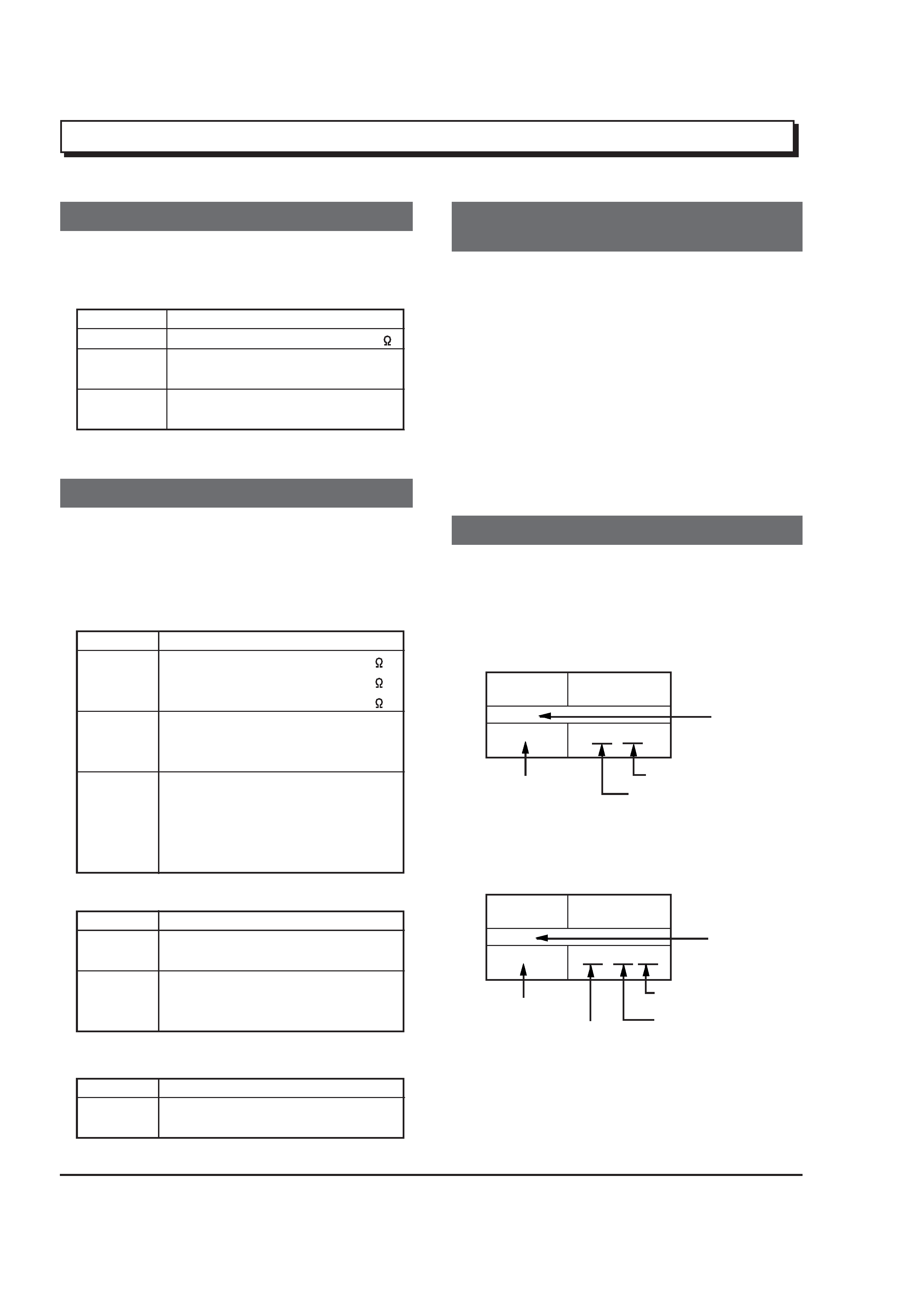
4. Table for indexing locations of parts
Parts
Location
2
A
Symbol
No.
IC
IC1201
Type of part
Zone "A" on board diagram
Circuit No.
Zone "2" on board diagram
Parts
Location
A - 2
A
Symbol
No.
IC
IC1201
Zone "2" on board
diagram
A: Shows side A
B: Shows side B
Zone "A" on board
diagram
Type of
part
Circuit No.