SERVICE MANUAL
SPECIFICATIONS AND PARTS ARE SUBJECT TO CHANGE FOR IMPROVEMENT
Digital Media Division
COLOR VIDEO CAMERA
August 2003
SM8303
VK-S454R
VK-S454ER

Table of Contents
1 Safety Precaution for Repair ............. 1-1
1-1 Cautions ................................................... 1-1
1-2 lectrostatic Protection Measures ............... 1-1
1-3 Lead-Free Solder ...................................... 1-2
1-4 Notes When Using Service Manual .......... 1-3
2 General Description ........................... 2-1
2-1 Overview .................................................. 2-1
2-1-1 Servicing method ................................... 2-1
2-2 Features ................................................... 2-2
2-3 Specifications ........................................... 2-3
2-4 Comparison from Previous Models ........... 2-5
2-5 Comparison of Main Control ICs ............... 2-6
2-6 List of Abbreviations and Terms for
Surveillance System ................................. 2-7
3 Description of Operation ................... 3-1
3-1 Structure Schematics ............................... 3-1
3-2 Microprocessor Pin Function Tables ......... 3-2
3-2-1 Camera microprocessor
(IC1201: Camera µP) ............................. 3-2
4 Troubleshooting .................................. 4-1
4-1 Trouble Diagnosis ..................................... 4-1
4-1-1 Setting to service position ...................... 4-1
4-1-2 Trouble diagnosis flowchart ................... 4-2
5 Disassembly and Reassembly .......... 5-1
5-1 Order of Disassembly ............................... 5-1
5-2 Disassembly ............................................. 5-1
6 Adjustment .......................................... 6-1
6-1 Preparations for Adjustment ..................... 6-1
6-1-1 List of equipment and jigs ...................... 6-1
6-1-2 List of test equipment and charts ........... 6-1
6-1-3 Connections for adjustment ................... 6-2
6-1-4 Setting test equipment ........................... 6-3
6-1-5 Starting adjustment program (ZMAP) .... 6-3
6-2 List of Adjustment Items ........................... 6-5
6-2-1 List of adjustments needed after
replacing major ...................................... 6-5
6-2-2 Adjustment flowchart ............................. 6-6
6-3 Data Initialize ............................................ 6-7
6-4 Electronic Volume ..................................... 6-7
6-4-1 CDS sampling pulse adjustment ............ 6-8
6-5 Adjustment (Camera Adjustment) ............. 6-8
6-5-1 Auto iris control adjustment ................... 6-9
6-5-2 White balance adjustment ..................... 6-9
6-5-3 Chroma gain adjustment ....................... 6-10
6-6 Auto Focus ............................................... 6-11
6-6-1 Zoom/focus tracking adjustment ............ 6-11
6-6-2 AF noise level adjustment ...................... 6-12
6-6-3 Check of zoom/focus trace .................... 6-12
6-7 Spot Noise ................................................ 6-13
6-8 IR Control ................................................. 6-14
6-9 Error Messages and Countermeasure ...... 6-15
7 Exploded View and Parts List ............ 7-1
7-1 Exploded View .......................................... 7-1
7-2 Replacement Parts List ............................ 7-2
7-2-1 Mechanical parts list .............................. 7-2
7-2-2 Electrical parts list ................................. 7-2
Schematic, Circuit Board and Block
Diagrams .................................................... 1
1 Wiring Diagram .............................................. 1
2 Schematic Diagrams ..................................... 2
2-1 Sensor [SP] Schematic Diagram ............... 2
2-2 Process [PC] Schematic Diagram ............. 3
2-3 Switching Reg. [CSR] ................................ 6
3 Circuit Board Diagram ................................... 7
3-1 PC Circuit Board Diagram ......................... 7
3-2 SP Circuit Board Diagram .......................... 8
3-3 CSR Circuit Board Diagram ....................... 8
3-4 Identification Parts Location ....................... 9
4 Block Diagrams ............................................. 10
4-1 Overall Block Diagram ............................... 10
4-2 Power Block Diagram ................................ 11
1 - 1
Safety Precaution for Repair
1
1-1 Cautions
Many electrical and mechanical parts have special safety-related characteristics. These are often not
evident from visual inspection nor can the protection afforded by them necessarily be obtained by using
replacement components rated for a higher voltage, wattage, etc. Replacement parts which have these
special safety characteristics are identified in this Service Manual. Electrical components having such
features are identified by marking with a
on the schematics and the parts list in this Service Manual.
The use of a substitute replacement component which does not have the same safety characteristics as
the HITACHI recommended replacement one, shown in the parts list in this Service Manual, may create
shock, fire, or other hazards. Product safety is continuously under review and new instructions are issued
from time to time. For the latest information, always consult the current HITACHI Service Manual. A
subscription to, or additional copies for, HITACHI Service Manual may be obtained at a nominal charge
from HITACHI SALES CORPORATION.
PRODUCT SAFETY NOTICE
1-2 Electrostatic Protection Measures
Semiconductor components can be damaged by static electricity charged on clothes, human body,
etc. Take great care when handling components to avoid electrostatic damage, and perform
servicing in an environment where grounding is complete.
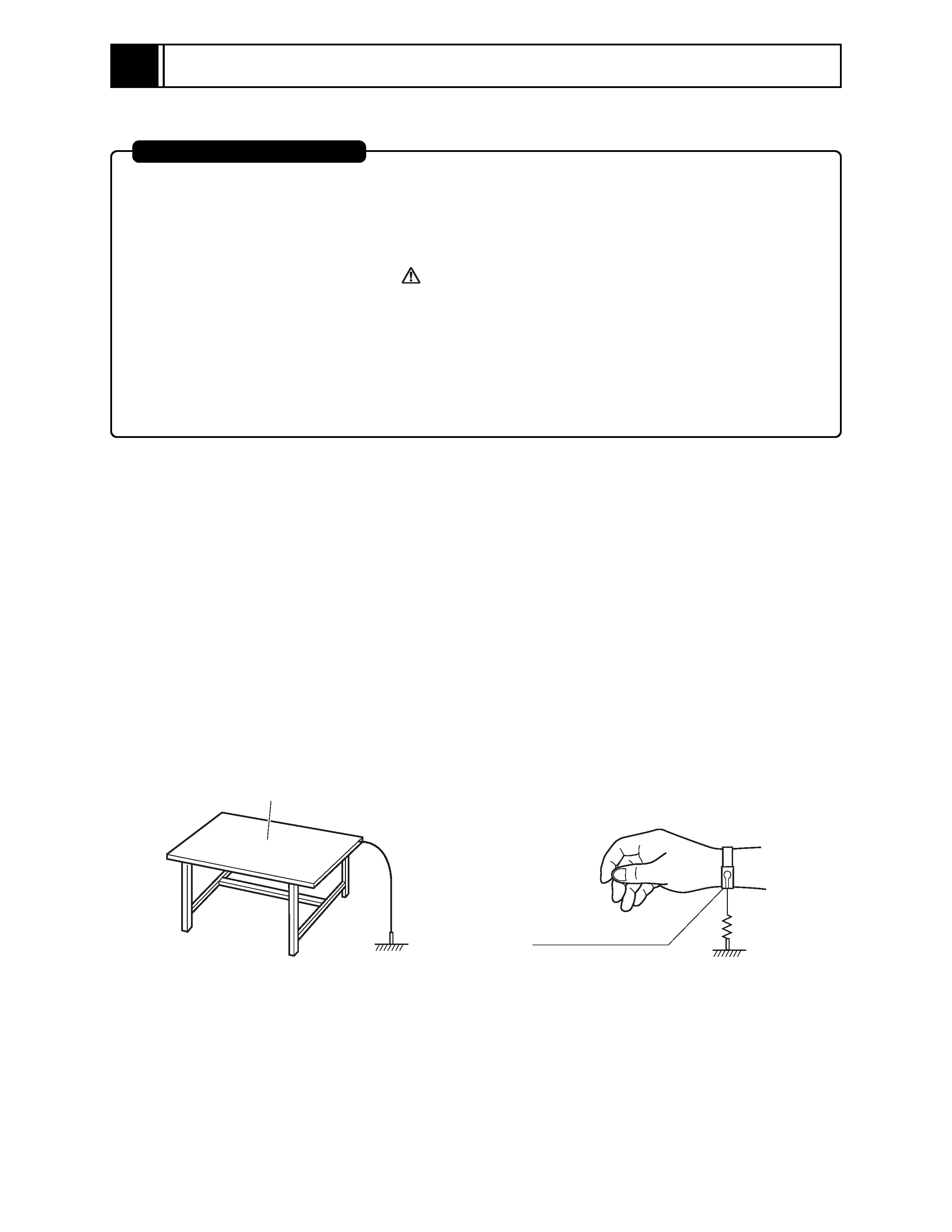
(1) Grounding work bench (Fig. 1-2-1)
Lay out an antistatic mat on work bench, and then use the ground plate to ground the work bench.
(2) Grounding human body (Fig. 1-2-2)
Use an antistatic wrist strap to discharge any static electricity charged on the body. Also, use a
tester for wrist strap to make sure that the wrist strap is working normally. Note, however, that
static electricity charged on clothes will not be discharged by wrist strap: Therefore do not allow
your clothes to touch the semiconductor components.
Fig. 1-2-1 Grounding Work Bench
Fig. 1-2-2 Grounding Human Body
Antistatic mat
Ground
1M ohm
Antistatic wrist strap
1 - 2
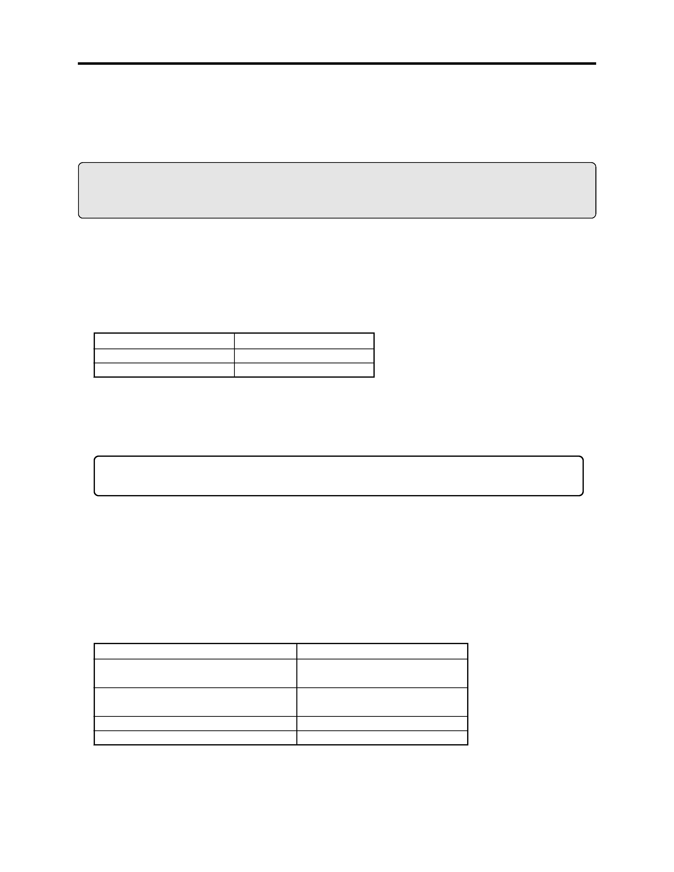
Point to be soldered
For reflow
For dip
Composition of alloy (wt%)
Solder paste: Sn-3Ag-0.5Cu
Bar solder: Sn-0.6Cu
1-3 Lead-Free Solder
The printed circuit board that uses lead-free solder is adopted. To protect the global environment,
use the recommended lead-free solder also during servicing.
Read and observe the following before soldering:
Caution
ALWAYS wear protective goggles during soldering so that no solder smoke or scattered solder
enters the eye. Lead-free solder may scatter at high temperatures of 600°C.
(1) Identification of circuit boards that use lead-free solder
"F" is stamped or noted with pattern letter on circuit boards that use lead-free solder.
(2) Characteristics of lead-free solder
The components of lead-free solder used are as follows. The melting point of lead-free solder is 30-
40°C higher than that of lead based solder:
Melting temperature: Approx. 220°C
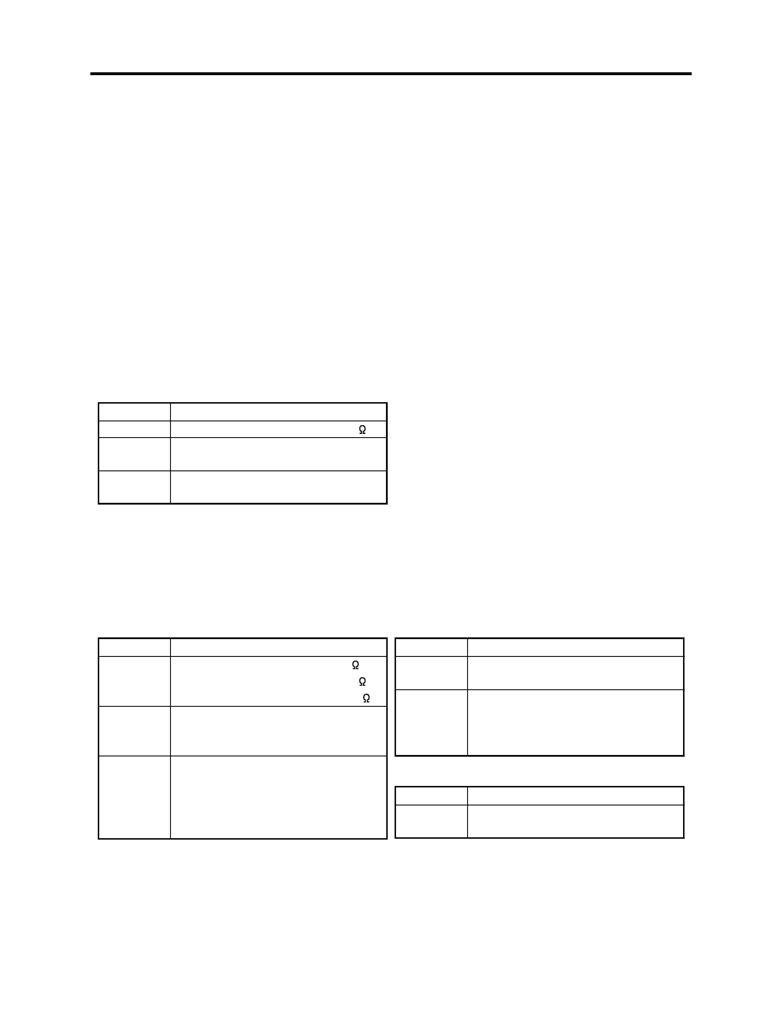
Point to be soldered
Surface-mounted (chip) parts [other than
those shown below]
Surface-mounted (chip) parts [for DVD
cameras, cellular phones only]
Discrete parts
Chassis, metal shield, etc.
Tip temperature
320 ± 30°C
[heating time: less than 5 seconds]
350 ± 10°C
[heating time: less than 3 seconds]
380 ± 30°C
420 ± 30°C
(3) Lead-free solder for servicing
Use the following lead-free solder for servicing:
Recommended lead-free solder and composition of alloy (wt%): Sn-3.0Ag-0.5Cu or equivalent
Information:
For composition of alloy, Sn is tin; Ag is silver; Cu is copper; Bi is bismuth; Pb is lead.
(4) Soldering iron for servicing
The temperature of soldering iron tip must be adjusted according to the points to be soldered: Use
an antistatic soldering iron with thermal control function.
When removing components, take care not to damage any surrounding component or pattern. When
attaching components, observe the heating time in the following table so that the components are
not destroyed by heat.
Tip temperatures for different soldering points:
Safety Precaution for Repair > Lead-Free Solder
1 - 3
(5) Cautions when using lead based solder
It is recommended that you use lead-free solder when servicing, but it is also possible to service
using lead based solder. However, if lead based solder is used for servicing, take care with the
following:
1) Before using lead based solder, remove the lead-free solder completely from the point to be
soldered.
2) For additional soldering for repair, set the soldering iron tip temperature for lead-free solder, mix
lead based solder and lead-free solder sufficiently. Do not perform any repair using the bare
soldering iron tip without adding solder, since it will cause secondary failure due to lack of
strength.
Safety Precaution for Repair > Lead-Free Solder / Notes When Using Service Manual
1-4 Notes When Using Service Manual
(1) Value units used in parts list
Certain symbols are indicated as shown below for value units of resistors, capacitors and coils in
parts list. When you read them, note the following regular indications:
(2) Values in schematic diagrams
The values, dielectric strength (power capacitance) and tolerances of the resistors (excluding
variable resistors) and capacitors are indicated in the schematic diagrams using abbreviations.
Certain symbols are indicated for value units: When you read them note the regular indications in
tables below:
[Resistors]
[Capacitors]
[Coils]
Indication in list
Regular indication
KOHM ......................................... k
UF................................................ µF
PF ................................................ pF
UH ............................................... µH
MH .............................................. mH
Parts
Resistor
Capacitor
Coil
Item
Value
Tolerance
Power
capacitance
Indication
No indication ..............................
K .................................................. k
M ................................................. M
No indication .............................. ±5%
(All tolerances other than ±5% are
indicated in schematic diagrams)
No indication .............................. 1/8W
(1/16 W for leadless resistors with no
indication)
All capacitances other than the above
are indicated in schematic diagrams.
Item
Value
Dielectric
strength
Indication
No indication .............................. µF
P .................................................. pF
No indication .............................. 50V
(All dielectric strengths other than
50 V are indicated in schematic
diagrams)
Item
Value
Indication
µ ................................................... µH
m .................................................. mH